ITFComp: A Compression Algorithm for ARM Architecture
Instruction Trace Files
Mohammad Qasem
Fraunhofer, FKIE Fraunhoferstr. 20 53343 Wachtberg, Germany
[email protected]
Lukas Pustina
CenterDevice GmbH Rheinwerkallee 3 53227 Bonn, Germany
[email protected]
ABSTRACT
Testing the performance of a new computational component is costly due to the need of prototyping different setups. There-fore, trace driven hardware simulations are used. Instruction Trace Files (ITFs) are files containing traces of executed in-structions in a program’s run and are used as an input for hardware simulations. ITFs tend to be large in size, causing a storage challenge. Many trace reduction techniques exist to deal with the ITFs’ storage challenge. In this paper we intro-duce ITFComp, a compression algorithm that combines general purpose compression methods with knowledge about ARM ar-chitecture ITFs’ structure to reduce their size. ITFComp also works on compressing data memory addresses accessed by in-structions within ITFs to further reduce an ITF size. Results show a reduction of 600 times on average when combined with LZMA compression algorithm. This reduction is 4 times better than when using LZMA alone, and 10 times better than when using DEFLATE. ITFComp introduces a negligible overhead in the decompression time (less than 1%).
Keywords
Performance, Instruction Trace Files, Compression, Memory Addresses, Hardware, Simulation, ARM, Architecture
1.
INTRODUCTION
In the recent years, there has been a wide spread of handheld computational devices, one of such devices is the smartphone. In the smartphone market, by 2014, more than 95% of used processors were of ARM architecture [11]. When a new smart-phone design is presented, its performance has to be tested. This process requires prototyping the design, and changing the prototype whenever a design change is suggested. Such proto-typing is costly in time and resources.
An alternative approach to prototyping is hardware simula-tions [3]. Hardware simulasimula-tions are done by designing a soft-ware component that simulates a hardsoft-ware component such as a CPU. The performance of the simulated hardware compo-nents is tested by executing instructions on them.
Instructions are recorded from an actual benchmark run on a similar hardware. Low level executed instructions of bench-marks are recorded in files calledInstruction Trace Files(ITF) in a process calledtracing. ITFs are used as an input for hard-ware simulations.
Modern processing units with clock speeds of few gigahertz execute billions of instructions per second. Therefore, recording the instructions of a program that lasts few seconds in execution would generate a very large ITF causing a storage challenge. Another factor that contributes to the storage challenge is the need most of the times to store multiple runs of the same benchmark with different inputs. This process creates multiple large ITFs per benchmark.
In this paper, we focus on presenting a solution for the ARM based ITFs storage challenge. ARM architecture was chosen due to its wide spread as an architecture in smartphones and handheld computational devices. The target ITFs are text files where each line represents an executed instruction during trac-ing. An executed instruction consist of an instruction address, the instruction, the parameters, and any optional flags or data memory accesses.
General purpose compression algorithms can be used to com-press ITFs. However, such algorithms lack knowledge of ITFs structure that could be used to further reduce an ITF size. Such knowledge also allows for being more flexible while decompress-ing ITFs by allowdecompress-ing for random access within the compressed files.
This knowledge comes from the fact that an ITF consists of repeating instruction segments calledbasic blockswith unique entry point and exit point. Instructions in repeating instances of the same basic block differ in execution flags, and data memory accesses of load and store instructions. Therefore, an ITF can be represented as a sequence of basic blocks identified by their entry points, instead of having to store instructions line by line. Differences between two instances of the same basic block can be stored separately.
In this paper, a compression algorithm for ARM based ITFs called ITFComp is introduced. This algorithm makes use of ITF structure mentioned earlier and combines it with general purpose compression methods to reduce ITFs storage require-ments. ITFComp reduces the size of ITFs more than general purpose compression algorithms, and it introduces a negligible (less than 1%) overhead on the decompression time.
ITFComp further reduces an ITF size by compressing data memory addresses accessed by the instructions within an ITF. ITFComp makes use of the locality and the access patterns that instructions usually follow when accessing the data memory [7]. In summary, ITFs are used in many performance related
stud-SIMUTOOLS 2015, August 24-26, Athens, Greece Copyright © 2015 ICST
ies, one of which is hardware simulations and testing. Hardware simulations saves time and money compared to prototyping different designs. ITFs tend to be large in size requiring com-pression. General purpose compression algorithms lack domain specific knowledge about ITFs structure. This knowledge could be used to further reduce ITFs size. In this paper, we suggest a new compression algorithm called ITFComp that makes use of such knowledge.
The remainder of this paper is as follows, the following sec-tion is an overview of the covered related work. An algorithm overview is given in the third section. The fourth section dis-cuss the first step of the algorithm: compressing the sequence of instructions in an ITF. The fifth section discusses the second step: compressing data memory addresses accessed in an ITF. The sixth section shows the used evaluation metrics and the results of evaluating the suggested algorithm. The last section is a summary.
2.
RELATED WORK
Many compression algorithms that are ITF specific exist. Some algorithms work on instruction traces, while others tar-get the data memory access traces. The presented ITFComp algorithm works on both instructions and memory addresses. Therefore, ITF specific compression algorithms of different tar-gets were overviewed. None of the found and reviewed algo-rithms deals with ARM text trace files as with ITFComp.
In this section, a summary of overviewed ITF specific com-pression algortihms is given. The overview is given in two sub-sections: Instruction traces compression algorithms, and mem-ory addresses compression algorithms.
2.1
Instruction Traces Compression Algorithms
For instructions compression, trace filtering was used in [8]. It is done by discarding parts of the ITF that have low impact on the simulation. This depends on which component in the target hardware is being evaluated.A compression method was proposed in [1] that works by storing a map between instruction addresses and instruction words. Once this is done, only addresses of instructions need to be stored in an ITF rather than the whole instruction. Following that, addresses are compressed by dividing them into sets of sequential and non-sequential groups of addresses. Each type of sets is compressed in a different way.
In [7], a compression method called PDI was introduced. The algorithm represents an extension for PDATS [6] memory trace compression algorithm and works in two steps: The first step scans an ITF looking for the most common 256 instruction words. The words are stored in a dictionary that maps values of 1-256 to the instruction words. Common instructions are replaced with a value of 1-256 corresponding to their dictionary index, while the rest are kept as they are. The second step is applied in a manner similar to PDATS, which is explained in the following subsection 2.2.
A compression algorithm that makes use of streams in ITFs was introduced in [9]. An instruction stream is a series of instructions that are executed sequentially until a flow chang-ing instruction. Streams are different from basic blocks for not having a unique entry and exit points. Therefore, some instructions might show in multiple streams. The algorithm detects instruction streams and stores the most common ones in a dictionary. Occurrences of common streams are replaced with their dictionary index.
Hardware based real time compression of ITFs was
intro-duced in [10]. The work is done by compressing instructions while tracing them in real time. The compression is done in a manner similar to the work in [9].
2.2
Memory Addresses Compression Algorithms
For memory addresses compression, two approaches were suggested in [15]. Both approaches work by sampling cache hits, either in a timely manner or depending on their level in the cache memory. Both approaches introduce a small error rate in simulations.PDATS [6] is a memory addresses compression algorithm. PDATS work on extracting the distances between data memory addresses, then applies run length encoding to compress them. This approach is lossless.
Another lossless compression scheme was suggested in [13]. The algorithm applies general purpose compression on the dis-tances between stored addresses in a memory trace file rather than the addresses themselves. Therefore, the algorithm repre-sents a generalization of PDATS mentioned earlier.
As mentioned earlier, none of the found and reviewed
meth-ods deals with ARM ITFs that are text based. Text based
ARM ITFs show instructions addresses, instructions, and their parameters.
3.
ALGORITHM OVERVIEW
ITFComp increases the reduction in size of ITFs when ap-plying general purpose compression. It achieves that by using knowledge about ITFs structure. As stated in the introduction, this knowledge is represented in basic blocks being the building components of an ITF, and memory access addresses locality and patterns. ITFComp uses this knowledge to compress an ITF in two steps, making it a multi-pass compression algo-rithm: compressing instructions after extracting data memory addresses, and compressing extracted memory addresses.
A basic block is a series of instructions that has a single unique entry point and a single unique exit point. Static basic blocks is a term used to define high level language blocks such as the body of a for loop. In an ITF, dynamic basic blocks exist. Dynamic basic blocks represent an execution of a static basic block or a part of it due to interrupts or flow changing instructions. In this paper, the term basic block is used for a dynamic basic block unless mentioned otherwise.
A basic block might show multiple times within an ITF, cre-ating different instances of the basic block. Instances of a basic block might differ in execution flags, or data memory addresses accessed by instructions within.
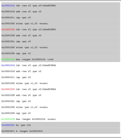
A segment of an ITF is shown in Listing 1. The segment con-tains two consecutive instances of the same basic block starting with the address0x10001014, and a third different basic block with the address0x1000103c. The two instances of basic block 0x10001014 differ in data memory addresses and flags as can be seen in the instructions 0x10001024, and 0x10001038 re-spectively.
Data memory addresses accessed by the same instruction usually exhibit locality among the different instances of its basic block. Accessed addresses follow certain patterns that could be used to allow for a high amount of reduction in size. For example, storing the distances between successive addresses rather than absolute addresses [13][6], reduces the amount of
space required for storage per memory access. An example
0x10001014ldr -res r3 -par r0:0xbe8f3940
0x10001018 add -res r2 -par r2
0x1000101c cmp -par r3
0x10001020 strne -par r1,r3-noexec
0x10001024ldr -res r3 -par r0:0xbe8f3950
0x10001028 add -res r0 -par r0
0x1000102c cmp -par r3
0x10001030 strne -par r1,r3-noexec
0x10001034 cmp -par r2
0x10001038bne -target 0x10001014-cond
0x10001014ldr -res r3 -par r0:0xbe8f3944
0x10001018 add -res r2 -par r2
0x1000101c cmp -par r3
0x10001020 strne -par r1,r3-noexec
0x10001024ldr -res r3 -par r0:0xbe8f3954
0x10001028 add -res r0 -par r0
0x1000102c cmp -par r3
0x10001030 strne -par r1,r3-noexec
0x10001034 cmp -par r2
0x10001038bne -target 0x10001014-noexec
0x1000103cbx -par r14
0x1000167c b -target 0x10001614
Listing 1: A segment of an ITF showing a repeating basic block, followed by a different basic block
example is having a periodic access pattern when reading from a list like structure sequentially.
ITFComp compression works by generating a list of basic blocks within an ITF by identifying their unique entry and exit points. It then proceeds by representing the ITF as a sequence of basic blocks identified by their unique entry points. One instance per basic block is stored as atemplate into a dictio-nary. A template is a basic block instance with data memory addresses and flags replaced with place holders.
Instructions are identified by their relative address in their basic block. For example, in Listing 1, the highlighted instruc-tion0x10001024 is identified as instruction number 16(hex 10) in basic block0x10001014. Data memory addresses are stored per instruction as the first accessed address by the instruction, and a list of distances to each consecutive access of that in-struction. Flags are stored within the basic blocks sequence of a compressed ITF in different sets. A flag set contains instruction numbers that has its flag within the next basic block.
The decompression of an ITF goes by reading the sequence of basic blocks. For each element, the stored basic block template from the dictionary is written. Missing data memory addresses and flags are added depending on the instance number.
The general sketch of the ITFComp algorithm mentioned in this section still lacks information such as data memory ad-dresses compression, and decompression processes details. Ex-tracting basic blocks and their sequence in an ITF is explained in the next section, while dealing with data memory addresses compression is detailed in Section 5.
4.
INSTRUCTIONS COMPRESSION
As explained in the previous section, the ITFComp algorithm
compresses an ITF in two steps: compressing instructions of the ITF, and compressing data memory addresses. In this section the first step is explained in details. The use of the result of this step during the decompression of an ITF is also detailed.
ITFComp detects the sequence of basic blocks executed in an ITF. It replaces them with their unique entry address resulting in a compressed file. For each basic block, one instance with data memory addresses and flags replaced with place holders to be filled during the decompression process is stored as a template.
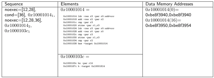
The result of the aforementioned process is a sequence of basic block unique entry addresses, with each having an in-stance number shown as an index on the address. Flags are stored into sets in the resulting basic blocks sequence, per ba-sic block. The sets contain the instruction numbers for which the flag should be added in the template during decompres-sion. An example of such sequence is shown in Table 1 under the ”Sequence” column.
As mentioned in the previous section, data memory addresses are extracted and stored per instruction. Instructions are iden-tified by their relative locations within their basic block. Ex-tracted data memory addresses compression is explained in the following section.
Table 1 is an example showing the result of compressing a segment of an ITF. The input segment used is shown in Listing 1 and consists of three basic blocks; two instances of the basic block0x10001014 and one instance of0x1000103c. The table contains the three elements resulting of the ITFComp algorithm; the sequence of basic blocks and the flag sets in the first column, the dictionary of templates in the second column, and extracted data memory addresses for each memory access instruction in the third column. One can notice that the more instances there is of a basic block, the higher reduction in size is achieved.
Interrupts are another issue to consider. Interrupts causes a change in the flow of execution during a basic block instance execution. Therefore, they cause a basic block execution dur-ing another. Interrupts of interrupts are also possible causdur-ing a hierarchy of basic blocks within basic blocks. ITFComp deals with this by identifying the basic block in the sequence as either abase basic block, or an interrupt basic block. An identifier is added to basic blocks in the sequence as a power of 1 or 2; 1 means it is a base basic block, and 2 means it is an in-terrupt basic block. Inin-terrupt basic blocks are followed by the instruction number at which the interrupt occurs.
An example sequence would be if an interrupt occurs af-ter the 4th instruction of the second instance of basic block 0x10001014 in Listing 1. The interrupt starting address is as-sumed0xffff08. The resulting sequence of basic blocks would be: 0x100010141
1,0xf f f f0821(5),0x1000101412,0x1000103c11.
Flag sets are used per base basic block. The sets account for their base basic block and any interrupt basic block within it.
The decompression process is done by going over the se-quence of basic blocks. Therefore, sets of flags, and interrupt basic blocks will be encountered before their base basic block. Once a base basic block is encountered, its template is read. For each instruction read from the template, its data memory address access is added if applicable. The flag sets and inter-rupt basic blocks locations are checked for possible additions after the read instruction.
Sequence Elements Data Memory Addresses noexec=[12,28],
cond=[36],0x100010141,
noexec=[12,28,36],
0x100010142, 0x1000103c1
0x10001014=
0x10001014 ldr -res r3 -par r0:address 0x10001018 add -res r2 -par r2 0x1000101c cmp -par r3 0x10001020 strne -par r1,r3 0x10001024 ldr -res r3 -par r0:address 0x10001028 add -res r0 -par r0 0x1000102c cmp -par r3 0x10001030 strne -par r1,r3 0x10001034 cmp -par r2 0x10001038 bne -target 0x10001014
0x10001014(0)= 0xbe8f3940,0xbe8f3940
0x10001014(16)= 0xbe8f3950,0xbe8f3954
0x1000103c=
0x1000103c bx -par r14 0x1000167c b -target 0x10001614
Table 1: The compressed sequence of the ITF segment in Listing 1
Once the base basic block is complete, the flag sets and interrupt basic blocks locations are reset. The decompression continues in the sequence and begins to generate instructions when the next base basic block is encountered.
Compressed data memory addresses are dealt with by decom-pressing the data memory address of an instruction depending on the instance number of the basic block read. Details of data memory addresses compression are in the next section.
5.
MEMORY ADDRESSES COMPRESSION
Memory addresses are compressed per instruction in the ITF. In this section, the requirements for data memory addresses compression for ITFComp are given, the different tested tech-niques for compressing data memory addresses are shown, and their functionality explained in the compression and the decom-pression steps.
Instructions are identified by their relative address in a basic block. The target ITFs are of ARM architecture; a RISK archi-tecture of a fixed 4 bytes instruction length (32-bit). Therefore, instructions are identified by numbers of multiples of 4, follow-ing the unique entry address of their basic block. This allows for storing instructions access addresses in a single data structure (e.g dictionary) that is identified by their basic block unique entry address.
Addresses accessed by an instruction follow patterns that can be made use of. Such patterns include having a constant location to access in the memory or a periodic access over a list like structure. This introduces the first requirement for data memory addresses compression which is to make use of such underlying knowledge of their access patterns.
During the decompression of the ITF, the required accessed address of an instruction in an instance of its basic block is to be provided. This adds the requirement of random access within the compressed data memory addresses. Random access is not usually provided by general purpose compression algorithms [2]. Data memory addresses are extracted during the compression process and stored per instruction. The addresses are extracted as a set of the first data memory address, and the distance to the following address until the last instance in the ITF. Storing distances allows for storing the addresses in lower space making use of locality [6]. It also allows for detecting simple patterns. Figure 1 shows an example where distances could be used to store data memory addresses as a constant value of four instead of a linear function. Addresses can be recovered by adding an
extracted distance to the previously generated address, starting from the first address, which is the first element in the set.
Figure 1: Data memory addresses accessed by an instruc-tion in a cjpeg algorithm run: Absolute (above), and dis-tances (below).
Since the application of the targeted ITFs is doing perfor-mance analysis on simulated hardware. Correctness of data memory addresses in the compressed ITF is not necessary. This allows for exploring lossy compression methods for data mem-ory addresses, as long as the performance of memmem-ory accesses in terms of cache misses and hits does not differ to a certain level [15].
Many algorithms have been tried that comply with the re-quirements of using knowledge of data memory addresses struc-ture, random access, and some being lossy. The tested al-gorithms were raw storage, periodicity detection, distribution compression, SEQUITUR, and patterns detection. Following is a summary of the used methods:
Raw Storage
Periodicity Detection
Compression: This method works by detecting periodic pat-terns in the distances of data memory addresses. It has been noticed that a periodic pattern is quite common in the ana-lyzed ITFs. This is explained by having many instructions that access a fixed variable, or access a list like data container, both of which are periodic access patterns. The used algorithm to detect periodicity was a brute force algorithm that extends from 1 element to half of the input data. In each step assuming a period, and verifying it. The algorithm has a complexity O(n), and a reduction of size equal to the period length over the length of the input data set.
Decompression: The required address of an instruction in its basic block instance numberNis retrieved by calculatingN modulo the period length. The element indexed by the result in the stored period is the required distance. Therefore, the decompression is O(1), allows for random access, and is not lossy.
Distribution Detection
Compression: This method works by representing the dis-tances of memory addresses as a distribution. The distribu-tion used is the histogram of the distances. The values of the histogram are chosen to guarantee a minimum of 50% reduc-tion in size. This is done by using at max, 25% of the total number of input elements as histogram values. The decision is done based on the number of unique elements, if less than the threshold, they are used. Otherwise, a uniform distribution with the threshold elements count is used. 25% was chosen as a threshold as it guarantees a good size reduction, and does not cause a large loss in the resulting addresses. Thresholds of 10%, 15%, 35% were evaluated as well.
Decompression: The decompression process goes by sam-pling a point from the distribution. Therefore, it has an O(1) run time, allows for random access, and is lossy.
SEQUITUR
Compression: The SEQUITUR [4] algorithm is used to infer a context free grammar on memory addresses distances.
Decompression: The decompression process is linear. The base rule of the resulting grammar is scanned, each character size is known, and if the terminal character (the required dis-tance) falls within/is one of the characters in the base rule, the character is expanded/chosen as the required distance. This gives the algorithm an access time of O(n). However, having information, about the number of terminal characters within a non-terminal one, allows for faster navigation within the base rule.
Patterns Detection
Compression: This algorithm represents an extension to the periodicity detection algorithm. The algorithm tries to detect less frequent patterns. The patterns are periodic with initializa-tion, periodic with terminainitializa-tion, and noisy periodic. A modified version of the linear search algorithm for periodicities was used to detect the first two types, and Autocorrelation was used to detect noisy periodic data. The algorithm complexity is O(nlog(n)) due to using Autocorrelation.
Decompression: This method allows for more compression on the aperiodic memory access addresses. However, it adds lossiness in the case of noisy periodic data. It allows for random access within the compressed data, and has an O(1) access time
for extracting addresses.
Table 2 shows a comparison between the different tested memory addresses compression methods in terms of being lossy, allowing for random access, and complexity.
During the evaluation of the used algorithms, due to their simplicity and good results, the periodicity detection and the patterns detection algorithms were used as bases for the other compression methods. When testing an algorithm, periodic-ity detection or pattern detection were applied first to com-press data memory addresses, and in the case of no detection, the target algorithm is used. Therefore, the algorithms SE-QUITUR, and distribution detection were applied on aperiodic data memory addresses in the presented evaluation results. In the next section, the evaluation of ITFComp, and a comparison with general purpose compression methods is shown.
6.
EVALUATION
For evaluation, three metrics were defined and used to eval-uate and compare ITFComp algorithm with general purpose compression methods. In this section, the metrics are defined, and the evaluation mechanism and results are shown.
General purpose compression methods were used as a refer-ence, as to the best of our knowledge, no previous work dealt with text based ARM ITFs compression. The covered work in the introduction deals with ITFs containing instruction words or data memory addresses.
The used metrics are mentioned below. Detailed definition of each metric is shown at their respective results sections:
1. Compression ratio: The metric measures the amount of reduction in size when a compression method is applied.
2. Simulated run time of the ITF: The metric measures the acceptability of a resulting ITF when decompressed.
3. Wall clock simulation time: The time required to decom-press an ITF and simulate it.
For these metrics, a simulator developed in [12] was used to simulate the compressed ITFs on an ARM9 architecture. The ITFs used in the evaluation process all belong to the MiBench [5] benchmark suit for ARM architecture. For ev-ery benchmark used, multiple ITFs generated executing that
benchmark with different inputs were used. The evaluated
benchmarks are: cjpeg, adpcm c, adpcm d, dijkstra, mad, crc, and blowfish e.
Following are the results of evaluating each metric.
6.1
Compression Ratio
This is a measure of the reduction in size in the ITF. There-fore, it is a measure of the efficiency of the compression method. This metric was used to evaluate ITFComp when using different data memory compression methods, and to compare ITFComp to general purpose and domain specific compression methods. The compression ratio is calculated as the size of the resulting compressed ITF over the size of the input uncompressed ITF. The lower the compression ratio is, the more size reduction on the input file there is.
Algorithm Random Read Lossiness Compression (O) Extraction (O)
Periodicity Detection Yes no O(n) O(1)
Distribution Detection Yes Yes O(n) O(1)
SEQUITUR No No O(n) O(n)
Patterns Detection Yes Yes O(nlog(n)) O(1)
Table 2: A comparison of the different tested compression methods for data memory addresses
there exist a high amount of patterns within data memory ad-dresses for the instructions in the evaluation set. It also shows that the distribution compression allows for a high compression ratio for random data.
sha adpcm_c adpcm_d cjpeg crc blowfish_e mad dijkstra Benchmarks (Multiple ITFs)
0.000 0.001 0.002 0.003 0.004 0.005 0.006 0.007 0.008 0.009
Co
mp
ressi
on
Ra
tio
Ba
rs:
Av
era
ge
, Bo
xe
s:
Dist
rib
uti
on
s
Compression Ratios: ITFComp using different memory compression methods Applied On ITFs Of Different Benchmarks
raw periodicity-raw periodicity-SEQUITUR periodicity-distribution patterns-distribution
Figure 2: The compression ratio of ITFComp using different data memory addresses compression methods. Multiple ITFs of different benchmarks were used as an input.
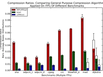
Figure 3 shows a comparison between three general pur-pose compression methods: DEFLATE(gz implementation) [2], bzip2 [14], and LZMA(xz implementation) [16], when applied on the evaluation set. The figure shows that LZMA(xz) algo-rithm achieves the lowest compression ratio, and therefore the highest reduction in size. For this, LZMA is used to compare the proposed ITFComp with.
Figure 4 shows a comparison between LZMA(xz) compres-sion method and ITFComp (using periodicity detection for data memory addresses compression and combined with LZMA com-pression). The figure shows that for the evaluation set, ITF-Comp managed to achieve a better average compression ratio than LZMA. The enhancement was up to 4 times in the case of adpcm for example.
ITFComp is also compared with the stream cache compres-sion algorithm (SC.I and SC.I+Ntup when combined with N-tuple) presented in [10]. The comparison is done on ITFs from the algorithms: cjpeg, mad, sha, and blowfish e. Table 3 shows the compression ratios achieved by ITFComp (periodicity-raw and periodicity-SEQUITUR memory addresses compression), compared to stream cache compression algorithm.
Table 3 shows that ITFComp achieves a better compression ratio for the used ITFs. When compared to SC.I,
ITFComp(periodicity-raw) achieves 6 times better compression on average. The
gain goes up to 625 times better for ITFComp(periodicity-SEQUITUR) for the blowfish e input. The results of SC.I+Ntup are better than those of SC.I. However, they still fall behind by
sha adpcm_c adpcm_d cjpeg crc blowfish_e mad dijkstra Benchmarks (Multiple ITFs)
0.00 0.01 0.02 0.03 0.04 0.05 0.06 0.07 0.08 0.09
Co
mp
ressi
on
Ra
tio
Ba
rs:
Av
era
ge
, Bo
xe
s:
Dist
rib
uti
on
s
Compression Ratios: Comparing General Purpose Compression Algorithms Applied On ITFs Of Different Benchmarks
DEFLATE(gz) bzip2 LZMA(xz)
Figure 3: The compression ratio of general puprose com-pression methods. Multiple ITFs of different benchmarks were used as an input.
2 times on average when compared to ITFComp(periodicity-raw).
In summary, ITFComp achieves the highest compression ratio when using patterns detection combined with distribution com-pression on data memory addresses. When compared to general purpose compression methods, ITFComp manages to achieve better compression ratios than the tested three general purpose compression methods. This shows that general purpose com-pression methods could use knowledge about ITFs to further reduce their size as this paper suggests. When compared to the domain specific stream cache compression method, ITFComp achieves better compression ratios. The compression ratio is 625 times better for some inputs.
6.2
Simulated Run Time
This is a measure of the correctness of the compressed ITFs. If the simulated run time of the compressed ITF matches that of the original ITF, it means that the used data memory ad-dresses compression had no effect on the performance charac-teristics of the simulated instructions. Otherwise, a change of the simulated run time would be allowed within an acceptable experimental threshold, given that the gain in the size reduction justifies it.
Two data memory addresses compression methods have lossy compression: patterns detection, and distribution detection. The amount of lossiness is reduced when combined with pe-riodicity compression as explained earlier. Figure 5 shows the simulated run time for compressed ITFs in the simulator [12]. Both lossy compression algorithms cause an increase in the sim-ulated run time.
ITFComp ITFComp SC.I SC.I+Ntup
(periodicity-raw) (periodicity-SEQUITUR)
cjpeg 0.00318 0.00198 0.0208 0.0068
mad 0.00181 0.00048 0.0123 0.00562
sha 0.00190 0.0011 0.0144 0.0023
blowfish e 0.00175 0.0000625 0.0391 0.0102
Table 3: The average compression ratio achieved by ITFComp compared with the stream cache algorithm.
sha adpcm_c adpcm_d cjpeg crc blowfish_e mad dijkstra Benchmarks (Multiple ITFs)
0.000 0.002 0.004 0.006 0.008 0.010 0.012 0.014 0.016 0.018
Co
mp
ressi
on
Ra
tio
Ba
rs:
Av
era
ge
, Bo
xe
s:
Dist
rib
uti
on
s
Compression Ratios: Comparing ITFComp (periodicity-raw) vs LZMA(xz) Applied On ITFs Of Different Benchmarks
LZMA(xz) ITFComp(periodicity-raw)
Figure 4: The compression ratio achieved by ITFComp combined with LZMA, compared to the general purpose compression algorithm LZMA(xz).
thing to notice is that the increase in the simulated run time is larger, the larger the simulated run time of the input ITF is. This can be explained by being more prone to lossy data memory addresses and cache misses in the decompressed ITF during a longer simulation.
6.3
Wall Clock Simulation Time
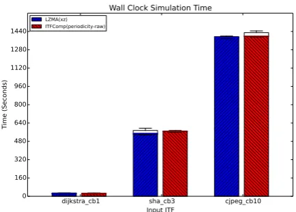
This is a measure of the decompression time of the ITFs during their simulation. ITFComp and LZMA(xz) compressed ITFs were decompressed and streamed into the used simulator. The wall clock simulation time was measured. The process was repeated 20 times for 3 different ITFs from 3 different benchmarks with varying sizes.
The results in Figure 6 show that on average, the decompres-sion and simulation time of ITFs for both compresdecompres-sion meth-ods is similar, with a slight increase for ITFComp. Therefore, ITFComp introduces a small overhead on the decompression process, but the ratio of that increase is negligible.
In summary, the three used metrics shows that the suggested compression method manages to reduce the size of ITFs on evaluation set more than general purpose and domain specific compression methods. It also shows that despite being lossy in some modes, the resulting compressed ITFs manages to keep their performance characteristics. However, there is a slight increase on the decompression time of the ITFs that can be ignored compared with the large simulation time.
7.
SUMMARY AND FUTURE WORK
Emulating hardware components during a new hardware de-sign is used to reduce its dede-sign costs in terms of money and
crc adpcm_c adpcm_d cjpeg blowfish_e sha mad dijkstra 1 3 18 1 3 8 9 10 15 16 18 8 14 16 20 1 2 6 7 9 10 12 13 14 18 7 8 11 14 1 2 3 8 11 13 14 15 16 18 19 1 3 10 16 1 2 3 8
Input Trace Files (Data Set, Algorithm) 0.0
0.1 0.2 0.3 0.4 0.5 0.6 0.7 0.8 0.9
Sim
ula
ted
Ru
n T
im
e (
s)
The Simulated Run Time Of ITFComp Compressed Trace Files Using Different Memory Addresses Compressions
raw periodicity-distribution periodicity-raw periodicity-SEQUITUR patterns-distribution
Figure 5: The simulated run time of compressed ITFs using different data memory addresses compression techniques in ITFComp.
dijkstra_cb1 sha_cb3 cjpeg_cb10
Input ITF 0
160 320 480 640 800 960 1120 1280 1440
Tim
e (
Se
co
nd
s)
Wall Clock Simulation Time
LZMA(xz) ITFComp(periodicity-raw)
Figure 6: The wall clock simulation time of three com-pressed ITFs using LZMA(xz) and ITFComp. The bar plots represent the average, while the boxes represent the distri-bution.
time. Hardware simulations use Instruction Trace Files (ITF) as an input, generated from tracing benchmarks and programs executed on similar hardware. ITFs tend to be large in size as with modern processors, billions of instructions are executed per second. This causes a storage challenge.
knowledge can be used to further reduce ITFs size when apply-ing general purpose compression to better deal with the storage challenge.
In this work, we present ITFComp; a new algorithm that deals with ARM architecture ITFs, as ARM architecture is used in most modern smartphones and hand held computational de-vices. ITFComp works by structuring an ITF into three com-ponents: a sequence of executed basic blocks, a template for each basic block, and data memory addresses accessed by in-structions within the ITF.
The list includes any special execution flags of the basic blocks, as well as information about interrupts. Templates are extracted from an instance of a basic block with all flags and data memory addresses replaced by place holders. Data mem-ory addresses are compressed in a way that allows for random access and use information about instructions access behaviors such as locality and patterns.
ITFComp helps to improve general purpose compression meth-ods on input files up to four times when compared to LZMA, and 10 times better when compared to DEFLATE. ITFComp achieves better compression ratios when compared to the do-main specific cache streams compression method.
Future work to enhance ITFComp would include finding pat-terns within the basic blocks list as there is usually locality within executed basic blocks. This locality is a result of high level language structures such as conditional basic blocks fol-lowing a loop body. More compression methods could be tested for data memory addresses. For example, a distributions that pay more attention to the samples order using heuristics. The list of basic blocks could also be used to partially decompress an ITF generating certain parts of interest for a specific simu-lation.
8.
REFERENCES
[1] C.W.E.N. CHEN, C.J. KU, and T.J.Y.E. LIU. Efficient trace file compression design with locality and address difference.
[2] L. Peter Deutsch. Deflate compressed data format specification version 1.3, 1996. RFC 1951 - Network Working Group.
[3] Davy Genbrugge, Lieven Eeckhout, and Koen
de Bosschere. Accurate Memory Data Flow Modeling in Statistical Simulation. In20th annual international conference on Supercomputing, pages 87–96, June 2006. [4] Craig G.Nevill-Manning and Ian H. Witten. Identifying
hierarchical structure in sequences: A linear-time algorithm.Journal of Artificial Intelligence Research, 7:67–82, 1997.
[5] M. R. Guthaus, J. S. Ringenberg, D. Ernst, T. M. Austin, T. Mudge, and R. B. Brown. Mibench: A free, commercially representative embedded benchmark suite. InProceedings of the Workload Characterization, 2001. WWC-4. 2001 IEEE International Workshop, WWC ’01, pages 3–14, Washington, DC, USA, 2001. IEEE Computer Society.
[6] E.E. Johnson and Jiheng Ha. Pdats lossless address trace compression for reducing file size and access time. In Computers and Communications, 1994., IEEE 13th Annual International Phoenix Conference on, page 213, apr 1994.
[7] E.E. Johnson, Jiheng Ha, and M. Baqar Zaidi. Lossless trace compression.Computers, IEEE Transactions on, 50(2):158 –173, feb 2001.
[8] N. Malik, R.J. Eickemeyer, and S. Vassiliadis. Architectural effects on dual instruction issue with interlock collapsing alus. InComputers and
Communications, 1993., Twelfth Annual International Phoenix Conference on, pages 42 –48, mar 1993. [9] A. Milenkovic and M. Milenkovic. Exploiting streams in
instruction and data address trace compression. In Workload Characterization, 2003. WWC-6. 2003 IEEE International Workshop on, pages 99–107, Oct 2003. [10] M. Milenkovic, A. Milenkovic, and M. Burtscher.
Algorithms and hardware structures for unobtrusive real-time compression of instruction and data address traces. InData Compression Conference, 2007. DCC ’07, pages 283–292, March 2007.
[11] ARM Holdings plc. Annual report 2013: Strategic report. Technical report, 2013.
[12] L. Pustina, S. Schwarzer, P. Martini, J. Muurinen, and A. Salomaki. A methodology for performance predictions of future arm systems modelled in uml. InSystems Conference, 2008 2nd Annual IEEE, pages 1–8, April 2008.
[13] A. Dain Samples. Mache: No-loss trace compaction. Technical Report UCB/CSD-88-446, EECS Department, University of California, Berkeley, Sep 1988.
[14] J. Seward. bzip2 and libbzip2.avaliable at http://www. bzip. org, 1996.
[15] A.J. Smith. Two methods for the efficient analysis of memory address trace data.Software Engineering, IEEE Transactions on, SE-3(1):94 – 101, jan. 1977.