Improved Person Identification System using
Face Biometric Detection
A. Dhanalakshmi 1and Dr. B. Srinivasan 2
1
Assistant Professor, PG & Research Department of Computer Science,
2
Associate Professor, PG & Research Department of Computer Science, Gobi Arts & Science College (Autonomous),
Gobichettipalayam – 638 453, Erode District, Tamil Nadu, India. Email ID: adgasc@gmail.com1, srinivasan_gasc@yahoo.com2
---ABSTRACT---Biometrics is measurable characteristics specific to an individual. Face detection has diverse applications especially as an identification solution which can meet the crying needs in security areas. While traditionally 2D images of faces have been used, 3D scans that contain both 3D data and registered color are becoming easier to acquire. Before 3D face images can be used to identify an individual, they require some form of initial alignment information, typically based on facial feature locations. We follow this by a discussion of the algorithms performance when constrained to frontal images and an analysis of its performance on a more complex dataset with significant head pose variation using 3D face data for detection provides a promising route to improved performance.
Keywords - Biometrics, Face, Face Sensor, Feature Extraction, Template Matching.
‐‐‐‐‐‐‐‐‐‐‐‐‐‐‐‐‐‐‐‐‐‐‐‐‐‐‐‐‐‐‐‐‐‐‐‐‐‐‐‐‐‐‐‐‐‐‐‐‐‐‐‐‐‐‐‐‐‐‐‐‐‐‐‐‐‐‐‐‐‐‐‐‐‐‐‐‐‐‐‐‐‐‐‐‐‐‐‐‐‐‐‐‐‐‐‐‐‐‐‐‐‐‐‐‐‐‐‐‐‐‐‐‐‐‐‐‐‐‐‐‐‐‐‐‐‐‐‐‐‐‐‐‐‐‐‐‐‐‐‐‐‐‐‐ Date of Submission: 20, January 2013 Date of Acceptance: 10, March 2013 ‐‐‐‐‐‐‐‐‐‐‐‐‐‐‐‐‐‐‐‐‐‐‐‐‐‐‐‐‐‐‐‐‐‐‐‐‐‐‐‐‐‐‐‐‐‐‐‐‐‐‐‐‐‐‐‐‐‐‐‐‐‐‐‐‐‐‐‐‐‐‐‐‐‐‐‐‐‐‐‐‐‐‐‐‐‐‐‐‐‐‐‐‐‐‐‐‐‐‐‐‐‐‐‐‐‐‐‐‐‐‐‐‐‐‐‐‐‐‐‐‐‐‐‐‐‐‐‐‐‐‐‐‐‐‐‐‐‐‐‐‐‐‐‐
I. INTRODUCTION
B
iometrics is measurable characteristics of an individual used to identify him or her. If a biometric identification system had been in place prior to September 11, the tragedy might have been avoided as several of the terrorists involved were already on government watch lists of suspected terrorists. The need to be able to automate the identification of individuals will become increasingly important in the coming years; watch lists are increasing in size and it is no longer realistic to expect human immigration agents to be able to keep up to date with the large number of people on these lists. This supports the need for the development of working biometrics.Biometric systems can function in verification or identification modes depending on their intended use. In a verification task, a person presents an identity claim to the system and the system only needs to verify the claim. In an identification task, an unknown individual presents himself or herself to the system, and it must identify them. In general, there are three approaches to authentication. In order of least secure and least convenient to most secure and most convenient, they are:
1.
Something you have - card, token, key.2.
Something you know- PIN, password.3.
Something you are - a biometric [1].The human face plays an irreplaceable role in biometrics technology due to some of its unique characteristics. First, most cameras are non-invasive; therefore face verification systems are one of the most
publicly acceptable verification technologies in use. Another advantage is that face detection systems can work mostly without the cooperation of the user concerned, which is therefore very convenient for the general users. A. Face Detection
The first task needed after the capture of an image is an initial alignment. The features commonly used to identify the orientation and location of the face is the eyes, nose, and mouth. This approach is the standard used on most facial biometric algorithms. After this stage, processing varies based on whether the application is identification or verification. Identification is the process of determining who someone is. Verification only needs to confirm that a subject is the person they claim to be [9]. In identification, the system compares the captured image (probe) to the gallery. The type of comparisons made depends both on the biometric used and on the matching algorithm in question. After the comparison, the system returns a rank ordering of identities.
B. Face Verification
reject the correct person) may be adjusted to balance ease of use with security.
II. FACIAL RECOGNITION
Facial recognition records the spatial geometry of distinguishing features of the face. Different vendors use different methods of facial recognition, however, all focus on measures of key features of the face. Because a person’s face can be captured by a camera from some distance away, facial recognition has a clandestine or covert capability (i.e. the subject does not necessarily know he has been observed). For this reason, facial recognition has been used in projects to identify card counters or other undesirables in casinos, shoplifters in stores, criminals and terrorists in urban areas [2].
A. 2D Face Recognition
Multiple local regions patches to perform 2D face recognition in the presence of expressions and occlusion. The motivation for this is that different facial expressions influence different parts of the face more than others. Algorithm addresses this belief by weighting areas that are less affected by the current displayed emotion more heavily. Reported results show that up to one-sixth of the face can be occluded without a loss in recognition, and one-third of the face can be occluded with a minimal loss [3].
B. 3D Face Recognition
The ICP algorithm to align 3D meshes containing face geometry. Their algorithm is based on four main steps: feature point detection in the probe images, rough alignment of probe to gallery by moving the probe centric
to match, iterative adjustment based on the closest point matching (ICP), and using known points (i.e. the eyes, tip of the nose and the mouth) to verify the match. Once this process is run, the ICP algorithm reports an average root mean-square distance that represents the separation between the gallery and probe meshes (i.e. the quality of the match) [3]. After running this process against their database of images with one gallery image and probe image per subject, they achieved a 95.6% rank one recognition rate with 108 images.
C. Biometric System Modules
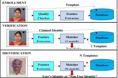
Enrollment Unit: The enrollment module registers individuals into the biometric system database. During this phase, a biometric reader scans the individual’s biometric characteristic to produce its digital representation (see figure 1).
Feature Extraction Unit: This module processes the input sample to generate a compact representation called the template, which is then stored in a central database or a smartcard issued to the individual.
Matching Unit: This module compares the current input with the template. If the system performs identity verification, it compares the new characteristics to the user’s master template and produces a score or match value (one to one matching). A system performing identification matches the new characteristics against the master templates of many users resulting in multiple match values (one too many matching).
Decision Maker: This module accepts or rejects the user based on a security threshold and matching score [1].
Figure 1: Block diagrams of Enrollment, Verification, and Identification tasks are shown using the four main modules of a biometric system.
Claimed Identity
ENROLLMENT
User Interface
Template
Quality
Checker
Feature
Extractor
Database
N Templates
1 Template
True/False
VERIFICATION
User Interface
Feature
Extractor
Matcher
(1 match)
Database
User’s Identity or “Non User Identity”
IDENTIFICATION
Feature
Extractor
Matcher
(N match)
III. FACE SENSOR
Face sensor using for both environment and the object to be scanned affect scanner accuracy and impose limitations on scanning. The material, geometry, or many other factors in the scanned object can cause decreases in accuracy or prevent successful scanning entirely. For example, secular materials are difficult to scan with lasers and discontinuous surfaces can yield scanning errors around edges. For this reason, it is difficult to define a single measurement to characterize accuracy. By focusing on a specific type of object (in our case, faces), we can provide a more detailed analysis for the scanner than is provided by most of the manufacturers. Further, faces themselves are rather complex with nontrivial geometry. As a result, they are a good test object to consider for different applications as well.
When attempting to determine the best scanner to use in a face recognition application, there are several factors to consider. There are accuracy levels in a scanner that are not necessary because faces can change more than that due to aging, weight, and expression. However, we will not explore that limit here since the majority of the scanners have accuracies in approximately tenths of a millimeter [6].
A. Scanner Assessment
In order to determine which of these devices is best for our application we also analyzed the accuracy of the points provided. While some of the vendors do make accuracy claims, attempting to compare those claims for our purposes may not be possible since most companies tend to test on the accuracy of sampling planar objects; this is not helpful here since faces are not planar. When examining the accuracy we needed a series of reference faces to use for the comparisons. However, using human faces is problematic because the human face is deformable and hence cannot serve as ground truth. No matter how much a person may try to keep the same face from one minute to the next, it can change significantly. Therefore, we constructed 3D face masks from real subjects in order to test the scanners. Since we were manufacturing the synthetic faces, we knew the ground truth values for them. In order to get the most realistic accuracy values possible, we produced ten faces consisting of five male and five female subjects.
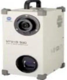
B. Konica Minolta Vivid 910
We ultimately decided to use the Konica Minolta Vivid 910 for all of our data collection. It provides a significantly higher level of detail than any of the other scanners we examined while still maintaining an accuracy level essentially tied with that of the Qlonerator. While the Qlonerator does provide better ear to ear facial coverage, it requires a significant offset between scanning pods which may not always be available.
The Minolta provides data in a grid structure. The points in focus provide valid range data, while points out of focal range do not provide range data allowing for easy segmentation of the foreground and background. We show an example of the difference between valid and invalid
range pixels where red are invalid range pixels and blue are valid range pixels.
The Minolta provides a 640 X 480 grid of points with color and registered range. The scanner is eye safe provided the subject does not circumvent the built in safety features. As mentioned above the scanner works well in a laboratory setting but will not work in direct sunlight or unusually bright light. While this scanner may not be the universal scanner ideal for a deployment situation, it captures the best data for our needs.
Figure 2: Vivid 910 by Konica Minolta
IV. FACIAL FEATURE DETECTION
We approach for locating the nose tip in 3D facial data. A hierarchical filtering scheme combining two “rules” to extract the points that distinguish the nose from other salient points. The first rule states that the nose tip will be the highest point in a certain direction that is determined by finding the normal’s on the face [4]. This rule eliminates many points, leaving a limited number of candidate points (the chin, the forehead, the cheeks, hair, etc.). The next rule attempts to model the cap-like shape on the nose tip itself. Each candidate point is characterized by a feature vector containing the mean and variance of its neighboring points. The vectors are projected into mean-variance space and a Support Vector Machine (SVM) is used to determine the boundary between nose tips and non-nose tips. The authors note that this rule also is challenged by wrinkles, clothing, or other cap-like areas on the face. The authors use three databases to test their algorithm. The largest database, the 3D Pose and Expression Face Models (3DPEF), contains 300 images of 30 subjects with small amounts of changes in pitch, yaw, and roll and a 99.3% nose detection rate is reported. A. Knowledge Based Methods
The classical work in this category is the multiple-rule based method. The main problem with knowledge-based methods is the difficulty of transforming human knowledge into rules described in computer languages, especially for 3-D rotated faces in different poses.
B. Template Matching
orient in a horizontal direction and that the vertical scale of the features are approximately equal.
C. Invariant Feature Methods
There are many works using various invariant features including gray values, edges, textures, color or a combination of these features. Among them, color is most widely used for face detection [5]. However, color information is not enough to correctly locate faces, although non-upright and non-frontal faces can be easily detected as candidates. It is therefore usually combined with other features such as edges or textures.
D. Object and Face Indexing
Face indexing method to reduce the search space of a database by placing images in different bins based on the subject’s hand geometry and written signature. First, feature vectors are found by taking various measurements on each type of image. Once the feature vectors are calculated, we use the k-means clustering algorithm to cluster images [8]. We uses database representing 50 users, each having 5 training images and 5 testing images for a total of 500 images. They are able to reduce the search space to 5% of the original size while not affecting the false reject rate (FRR). Using a point matching system, their technique calculates the similarity between two objects and a nearest neighbor method is used to determine the closest object prototype.
V. SYSTEM DESIGN
System design is a transition from a user-oriented document to a document oriented to programmers or database personnel. It goes through logical and physical design with emphasis on the following:
Preparing input/output specifications. Preparing security and control specifications. Specifying the implementation plan.
Preparing a logical design walkthrough before implementation.
As a biometric, facial recognition is a form of computer vision that uses faces to attempt to identify a person or verify a person’s claimed identity. Regardless of specific method used, facial recognition is accomplished in a five step process [7].
1. First, an image of the face is acquired. This acquisition can be accomplished by digitally scanning an existing photograph or by using an electro-optical camera to acquire a live picture of a subject. As video is a rapid sequence of individual still images, it can also be used as a source of facial images.
2. Second, software is employed to detect the location of any faces in the acquired image. This task is difficult, and often generalized patterns of what a face “looks like” (two eyes and a mouth set in an oval shape) are employed to pick out the faces.
3. Third, once the facial detection software has targeted a face, it can be analyzed. As noted in slide three, facial recognition analyzes the spatial geometry of distinguishing features of the face. Template generation is the result of the feature extraction process. A template is a reduced set of data that represents the unique features of an enrollee’s face.
4. The fourth step is to compare the template generated in step three with those in a database of known faces. In an identification application, this process yields scores that indicate how closely the generated template matches each of those in the database. In a verification application, the generated template is only compared with one template in the database – that of the claimed identity.
5. The final step is determining whether any scores produced in step four are high enough to declare a match. The rules governing the declaration of a match are often configurable by the end user, so that he or she can determine how the facial recognition system should behave based on security and operational considerations.
VI.IMPLEMENTATION OF SYSTEM
In order to implement this new biometric approaches for improved person identification using facial detection efficiently, ASP.NET program is used. This program could speed up the development of this system because it has facilities to draw forms and to add library easily [6]. A. Face Detection Algorithm
Automatic facial feature detection algorithms tested and designed for algorithms in 2D or 3D image. Facial feature detection algorithms operating on 2D color and grayscale images exist and are able to identify the eyes and mouth somewhat reliably. Examples of current methods for identifying facial features use Eigen features, deformable templates, Gabor wavelet filters, color manipulation methods, Edge Holistic, graph matching, etc.
B. Feature Extraction
nearest neighbor vector in a gallery to identify who the person is most likely to be. Performance for this varies widely and this type of biometric can be used in different forms for almost any distinguishing feature including face as well as being applicable for different types of measurements including 2D, 3D, or infrared images. This method is not limited to biometrics either and can be applied to generic object identification.
C. Datasets
We proposed a method using face curvature to identify facial features. Similar to, this shape based approach identifies facial features, but does identify more facial features than. The additional facial features are needed because to use these facial features not just for an alignment but uses information about these features (such as eye width) as recognition metric as well. Her method worked well, however it was tested on an extremely small database of 24 range scans which is too small to accurately assess performance on much larger real world datasets.
D. Data Acquisition
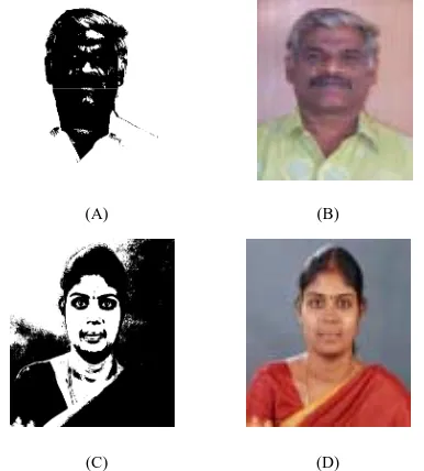
The Minolta scanner uses triangulation with a laser stripe projector to build a 3D model of the face from a sequence of profiles. Both color (r, g, b) and 3D location (x, y, z) coordinates are captured, but not perfectly simultaneously, and the laser stripe requires a few seconds to cross the face. The resolution on the Minolta camera is 640x480, yielding a maximum of 300,000 possible sample points. The number of 3D points on a frontal image of the face taken by the Minolta camera is typically around 112,000, and depends on the lens used as well as standoff. Additional vertices arise from hair, clothing, and background objects [7]. Example images from this sensor can be seen in Figure 3.
(A) (B)
(C) (D) Figure 3: Examples of images captured with the Vivid 910
by Minolta (A and C) 3D shape data for two different subjects (B and D) associated 2D color texture
information.
VII. TESTING BIOMETRIC SYSTEM
All biometric tests are accuracy based. A summary of the more common of these tests is described below:
Acceptance Testing: The process of determining whether an implementation satisfies acceptance criteria and enables the user to determine whether or not to accept the implementation. This includes the planning and execution of several kinds of tests (e.q., functionality, quality, and speed performance testing) that demonstrate that the implementation satisfies the user requirements.
Interoperability Testing: The testing of one implementation (product, system) with another to establish that they can work together properly.
Performance Testing: Measures the performance characteristics of an Implementation Under Test (IUT) such as its throughput, responsiveness, etc., under various conditions.
Robustness Testing: The process of determining how well an implementation processes data which contains errors.
VIII. EXPERIMENTAL RESULTS
The samples used for evaluation of the framework were organized as one gallery and three probe databases. The gallery database has 30 neutral faces, one for each subject, recorded in the first data acquisition session. Three probe sets are formed as follows:
Probe set 1: 30 neutral faces acquired in the second session.
Probe set 2: 30 smiling faces acquired in the second session.
Probe set 3: 60 faces, (probe set 1 and probe set 2 together).
The validation experiments were organized as follows: Experiment 1: Testing the neutral and smiling recognition modules separately
1.1 Neutral face recognition: probe set 1. (Neutral face recognition module used.)
1.2 Neutral face recognition: probe set 2. (Neutral face recognition module used.)
1.3 Smiling face recognition: probe set 2. (Smiling face recognition module used.)
Experiment 2: Testing a practical scenario
2.1 Neutral face recognition module used alone: probe set 3 is used
2.2 Integrated expression and face recognition: probe set 3 is used. (Linear discriminate classifier is used for expression recognition.)
2.3 Integrated expression and face recognition: probe set 3 is used. (Support vector machine is used for expression recognition.)
recognition module for neutral faces (probe set 1) in sub-experiment 1, and the much lower rank-one recognition rate (57%) achieved by this same module for smiling faces (probe set 2), in sub-experiment 2. In contrast, the third sub-experiment confirmed that a module that has been specifically developed for the identification of individuals from smiling probe images (probe set 2) is clearly more successful in this task (80% rank-one recognition).
Experiment 2 simulated a more realistic scenario, in which the expression in the subject is not controlled. Accordingly, for all three sub-experiments in Experiment 2 we used the comprehensive probe set 3, including one neutral range image and one smiling range image from each of the subjects. In the first sub-experiment we observe the kind of results that could be expected when these 60 probe images are processed by a “standard” neutral face recognition module alone. It was observed that with a mix of neutral and smiling faces this simple system only achieves 77% rank-one face recognition. This result highlights the need to account for the possibility of a
non-neutral expressions in 3D face recognition systems. On the other hand, in sub-experiments two and three we apply the same mixed set of images (Probe set 3) through the complete process depicted in our proposed framework. The right-most four columns whether using the linear discriminate analysis classifier or the support vector machine for the initial expression sorting, the rank-one face recognition levels achieved by the overall system are higher (87%, 85%).
IX. CONCLUSION
The work represents an attempt to acknowledge and account for the presence on face detection, towards their improved identification. We have focused on models of identify, features extraction and classification of the face authentication problem. Major challenges and their corresponding solutions are discussed. Some commercial systems available in the industry market are introduced briefly along with the face recognition. Classification is a step which must be complemented with feature extraction in order to demonstrate detection accuracy and performances. Its use has been successful with little to no exception, and face detection will prove to be a widely used security measure in the future. In the meantime, we, as a society, have time to decide how we want to use this new technology. By implementing reasonable safeguards, we can harness the power of the technology to maximize its public safety benefits while minimizing the intrusion on individual privacy.
REFERENCES
[1] A.K.Jian, R.Bolle, S.Pankanti(Eds), “ Biometrics-personal identification in networked society” 1999, Norwell, MA: Kluwer.
[2] C.Hesher, A.Srivastava, G.Erlebacher, “A novel technique for face recognition using range images” in the Proceedings of Seventh International Symposium on Signal Processing and Its Application, 2003.
[3] K. Bowyer, K.Chang, P. Flynn, “A survey of approaches to 3D and multi-modal 3D+ 2D face recognition” in IEEE International Conference on Pattern Recognition, 2004: pages 358-361.
[4] P.Ekman, W. Friesen, “Constants across cultures in the face and emotion,” in Jounal of Personality and Social Psychology, 1971. 17(2): pages 124-129. [5] C.Li, A.Barreto, “Profile-Based 3D Face Registration
and Recognition”. in Lecture Notes on Computer Science, 2005. 3506: pages 484-494.
[6] C.Li, A.Barreto, J.Zhai, and C.Chin, “Exploring Face Recognition Using 3D Profiles and Contours” in the Proceedings of IEEE Southeast on 2005: pages 576-579.
[7] C. Garcia and M. Delakis, “Convolutional face finder: A neural architecture for fast and robust face detection,” IEEE Trans. Pattern Anal. Mach. Intell., vol. 26, no. 11, pp. 1408–1423, Nov. 2004.
[8] R. Wang, J. Chen, S. Yan, S. Shan, X. Chen, and W. Gao, “Face detection based on the manifold,” in Audio- and Video-Based Biometric Person Authentication. Berlin, Germany: Springer-Verlag, 2005, pp. 208–218.
[9] R. Osadchy, M. Miller, and Y. LeCun, “Synergistic face detection and pose estimation with energy-based model,” in Advances in Neural Information Processing Systems. Cambridge, MA: MIT Press, 2005,pp. 1017–1024.
SHORT BIO DATA OF THE AUTHOR
A. DHANALAKSHMI M.C.A., M.Phil., Assistant Professor, PG & Research Department of Computer Science, Gobi Arts & Science College (Autonomous), Gobichettipalayam – 638 453, Erode District, Tamil Nadu, India. She received her M.Phil Degree in Computer Science from Bharathidasan University in August-2004. She has authored or co-authored more than 6 conference presentations. Her research interests include Biometrics and Advanced networking.
Dr. B. SRINIVASAN M.C.A., M.Phil., M.B.A., Ph.D.,