Static Application Panels (SAP) Controlled by PLC
V.Mathavi & Dhivya.N
M.Tech (Food Technology)
College of Food & Dairy
Technology,Chennai-52, India
G.Sujatha
Assistant Professor
College of Food & Dairy
Technology,Chennai-52, India
R.Chandrakala,
B.Tech (Food Technology)
College of Food & Dairy
Technology,Chennai-52, India
ABSTRACT
Programmable Logic Controller (PLC) is a digital computer for automation of process such as control of instruments in industries. It uses a programmable memory to store instructions and specific functions that include ON/OFF control, timing, counting, sequencing, arithmetic, and data handling. The basic parts include processor, input/output devices, memory unit, programming panel and power supply. Static Application Panels are designed to produce input and output from the PLC. Early electrical control systems were composed of mainly relays and switches. A relay, or contactor, is an electromagnetic device composed of a frame (or core) with an electromagnet coil and contacts with some movable and some fixed parts. Due to its disadvantages like chattering, complicated wiring and less flexibility relays are replaced by PLC. The SAP panels and ladder programmes were developed for automatic bottle filling machine, water level controller, logic gates and counter and comparator. Ladder programme is downloaded into PLC and verified with SAP model. According to the condition and comments provided in the ladder programme the SAP model works, if any deviation in the comments provided and this can be modified in the ladder diagram. This paper explain about the PLC, SAP model and ladder diagram designed for bottle filling machine, water level controller, logic gates and counter and comparator.
General Terms
Static Application Panel, SAP, Solenoids, Simulation, Programmable Logic Controller, PLC, Modules, Patch Cards, Ladder programme.
Keywords
Inputs, Outputs, Normally open, Normally closed, Relay, Timers.
1.
INTRODUCTION:
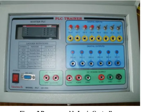
The static application panels (SAP) are simulation modules of various applications that usually come across in industrial environment such as motor control, level controlling, process controlling, industrial automation. For each SAP model, panels are designed accordingly. Terminals to connect input and output are brought outside the panels. SAP modules are just input and output devices to PLC. The Input is given from a push button or Toggle switch representing a sensor or a switch. The output is connected to a LED indicating a motor or a relay or a bulb status whether ON/OFF. All the panels have different problem statement to be solved. These SAP are just simulation modules and not exact working modules. But they use all the parameters required in the exact applications. Instead of motor LED is switching on or toggle switch is used for sensing the object or starting the process cycle. Where in
the real application motors, proximity sensors, limit switches are used for control applications. SAP models are designed with care so that the connections can be made very easily and self explanatory. The system works on 230V 50Hz AC Mains. Each SAP module requires digital input and digital output. In the main panel of PLC the digital I/O’s are brought out to the panels and clearly designated.
Digital input as DI-0, DI-1, DI-2….. Digital output as DO-0, DO-1, DO-2….
In all the SAP modules the required input and output are brought out to the terminals and designated accordingly.
2.
Programmable Logic Controllers
(PLC):
Programmable Logic Controller (PLC) is a specialized computer used to control machines and process. It is developed to offer the same functionality as the existing relay logic systems. It uses programmable memory to store instructions and specific functions that include ON / OFF control, timing, counting, sequencing, arithmetic and data handling [3] [4] [8] [12]. Control programmes are easily designed and coded using ladder diagrams which can be executed by PLC [14]. The basic parts of PLC include processor, memory unit, input/output devices, programming panel and power supply [1].
Processor (Central Processing Unit) module is the brain of the PLC. Intelligence of the PLC is derived from microprocessor being used which has the tremendous computing and controlling capability.Modern day PLCs vary widely in their capabilities like some processors are able to handle the I/O devices as few as six and some are able to handle 40000 or more. The no. of input/output control of PLCs depends on the, hardware, software, overall capacity and memory capability of the PLCs. Processor interprets input signals and carries out the control action according to the programme stored in its memory [11].
The type of input module selection depends upon the process, some example of input modules are limit :-switches, proximity switches and push buttons etc. nature of input classification can be done in three ways like low/high frequency, analog/digital (two-bit, multi-bit), maintained or momentary, 5V/24V/110V/220V switched.
Figure 1 Basic structure of PLC
Programming Unit is an external, electronic handheld device which can be connected to the processors of the PLC when programming changes are required. Once a program has been coded and is considered finished, It can be burned in to ROM. The contents of ROM cannot be altered, as it is not affected by power failure. Based on size PLC is classified as
Nano PLC- up to 16 I/O points
Micro PLC – up to 32 I/O points
Allen Bradley SLC-500 family – 960 I/O points
Allen Bradley PLC-5 family –several thousand I/O points
3.
PLC SPECIFICATION:
Basic units 500eco offer ample configuration range. Each basic unit incorporates a specific number of binary inputs / outputs. It is possible, depending on the basic unit, to increase the number of inputs / outputs, to add as 6 extensions connected directly to the basic units or remote input / output units via the CS 31 twisted pair.
Figure 2 Programmable Logic Controller
PLC can configure up to 110 binary inputs / outputs or 48 analog inputs / outputs for series 40 basic unit or remote unit. Make ABB Model:AC500eco series
No of IOs Incorporated binary inputs : 8PNP & NPN
Normal value : 24V DC
Filtering standard time : 5ms No of outputs : 6 transistors
Current : 2A
Voltage : max 24V DC No of 6
Extension
PC interface 1 RS-485 Serial port
Memory User program memory : 128 Kbyte Data memory : 10 Kbyte
Functionality Execution time for 1000 instruction:
Binary : 0.3ms
Word : 0.3ms
Floating point : 0.6ms
Programming Programming software : PS501 Control Builder
3.1 TRIANER SPECIFICATION:
Power supply
230V 50Hz
Available DC power supply
-DC 24V at 1A
-DC + & -15V at 500mA -AC 24V at 500mA Input 4mm socket (yellow) 8 No
Simulation: 4 No push button ,4No Toggle switch
Output 4mm socket (blue) 6No Simulation : 6 No LED Enclosure Metal box with powder coated
Dimension : (WxDxH) 350x250x150
Patch cards 4mm Yellow Banana Socket with 1M wire 8No
4mm Blue Banana Socket with 1M wire 6No 4mm Red Banana Socket with 1M wire 4No 4mm Green Banana Socket with 1M wire 4No 4mm Black Banana Socket with 1M wire 1No
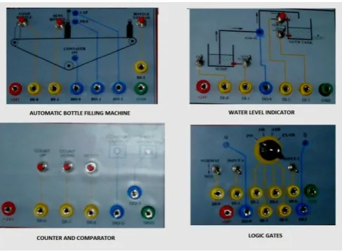
4.
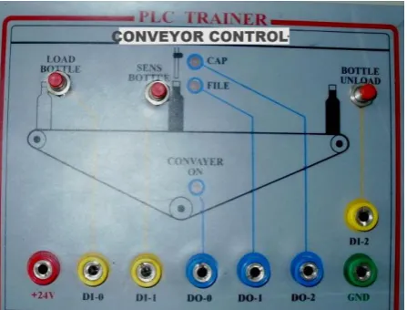
Automatic bottle filling machine:
Figure 3 Conveyor controller
4.1 Ladder diagram:
Ladder diagrams are specialized schematics commonly used to document industrial control logic systems. They are called "ladder" diagrams because they resemble a ladder, with two vertical rails (supply power) and as many "rungs" (horizontal lines) as there are control circuits to represent. Ladder diagram is easy to understand, check, troubleshoot and to modify and it takes less time to enter into the controller’s memory [6] [7] [11]. Ladder diagram input and output devices are as follows,
DEVICE ONE/ZERO INTERPRETATION
INPUT Contact no contact
Limit switch Pushbutton switch Timer
Control relay Circuit breaker
Contact /no contact On/off
On/off
Contact/no contact
OUTPUT
Motor Alarm buzzer Control relay Lights Valves Solenoid
On/off On/off
Contact/no contact On/off
Closed/open
Energized/not energized
Ladder diagram interpretation for conveyor control:
Step 1: When the bottle is loaded the sensor senses the bottle and conveyor becomes on mode
Step 2: Bottle is sensed and filling takes place for a particular time period as per timer
Step 3: After filling conveyor becomes on and then capping takes place.
Step 4: After capping the conveyor on and unloading of bottle takes place.
5.
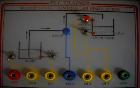
Water level controller
microcontroller. The main components used in this equipment are PLC microcontroller, sensor and motor. The sensors sense the presence of water and give indication to the microcontroller. The microcontroller produces the control signals to drive the motor. If there is no water then microcontroller gives control signal to start the motor and if there is sufficient water in the field then the microcontroller give control signal to stop the motor. Hence the level of water in a field can be automatically controlled [9].
Figure 4 Water level controller
5.1
Ladder diagram interpretation for Water level controller:
Step 1: Initially the tank is empty.
Step 2 : The internal relay is turned on as the water level raises.
Step 3 : After 2nd step the water level raises above the low level sensor and becomes open. Step 4 : After 3rd step the water level raises above the high level sensor and it also become open. Step 5: And therefore no true logic path and therefore the motor turned off
Step 6: After 5th step the water level falls below the high level sensor and it will become true again.
6.
Logic gates:
A logic gate is an idealized or physical device implementing a Boolean function, that is, it performs a logical operation on one or more logic inputs and produces a single logic output. Logical values can easily be expressed by an electrical circuit.“True” or “1” can be defined as voltage on a wire while “False” or “0” can be defined as no voltage. There are 3 basic elements of logic control namely AND,OR & NOT gate [2].
7.
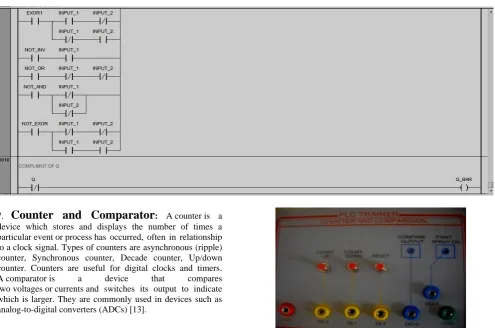
Counter and Comparator
: A counter is a device which stores and displays the number of times a particular event or process has occurred, often in relationship to a clock signal.Types of counters areasynchronous (ripple) counter, Synchronous counter, Decade counter, Up/down counter. Counters are useful for digital clocks and timers. A comparator is a device that compares two voltages or currents and switches its output to indicate which is larger. They are commonly used in devices such as analog-to-digital converters (ADCs) [13].Figure 6 Counter and comparator
Figure 7 All SAP models
COMPARISON BETWEEN RELAY AND PLC:
Relay PLC
Operating on analog system Operating on digital system The maximum time any
change in input is reflected in any output is t1
The maximum time any change in input is reflected in any output is t1+t2+…+ Tn. It is possible to replace. A
logic section without stopping execution of other logic sections if wired correctly.
The micro-controller must be halted to replace a logic section. All other logic sections will stop operation. Since parallel execution of
logic sections, all outputs are a function of one set of inputs.
Since serial execution of logic sections, all outputs may not be a function of one set of inputs.
Relay is complex than PLC PLC is much less complex than large relay system. It is less flexible PLC is the very flexible due
to network architecture Relay does not have self
documenting system
PLC is the virtually self-documenting
Requires more space than PLC
PLC is very space efficient and less manpower required to install.
It has complicated wiring system
PLC has no complicated wiring compare to relay panel. Difficult to handle the relay
system.
PLCs training and operating is very easy to handle its hardware and programming is also easy to learning.
8.
Conclusion:
The implementation of the PLC was carried out effectively for various industrial applications. It proves to be one of the important controllers in industries for its simplicity and robustness. PLC’s are very good for controlling outputs based on the inputs. Compared to relays PLCs are almost always a better choice. Lack of standardization is also one of the major disadvantages of the PLC. In the bottle filling system, only one limit switch was used to detect the position of the bottle.
This process has become quite obsolete; instead IR sensor can be used. It will be better if we add more sensors in this system like a flow sensor to detect water flow or use level sensor to detect water level. The ladder diagram for conveyor control, water level controller, logic gates, counter and comparator was prepared and downloaded into PLC, also verified with SAP model of the same. The performance of the working model was evaluated for each SAP model. One of the problem was notified in the filling function of the water level controller. Then the ladder diagram was modified and troubleshoot was made in the PLC. For effective process control the PLCs, ladder diagram and SAP models are inevitable and also cost effective.
9.
REFERENCES
[1] Festo, 2002. Programmable Logic Controllers –Basic levels. Text book TP 301
[2] Goodheart-Willcox Co.Inc., Programming Logic Gate functions in PLC’s
[3] IE 447 CIM Lecture Notes-Chapter 9-PLC-124
[4] John R. Hackworth and Frederick D. Hackworth, Jr. PLC Programming Methods and Applications
[5] Kalaiselvi.T,Praveena.R, Aakanksha.R, Dhanya.S, 2012. PLC Based Automatic Bottle Filling and Capping System With User Defined Volume Selection.Volume 2, Issue 8.134-137
[6] Pessen.D.W, 1989. Ladder diagram design for Programmable Logic Controllers. Automatica vol 25, No 3, pp 407-412.
[7] PLC Ladder diagram and the coding rules of Mnemonic. [8] Raja Narayanasamy, 2010.Designing an efficient
Programmable Logic Controller using Programmable System On Chip.Published in EE Times Design (http://www.eetimes.com/design, Pg 1 -7
[9] Ramazan Bayindir & Yucel cetinceviz. 2011. A water pumping control system with a Programmable Logic Controller (PLC) and industrial wireless modules for industrial plants – an experimental set-up. ISA Transactions 50 (2011), pp 321-328
[10] Ridgway.J.S, Henthorn.K.S & HullJ.B. 1999. Controlling of overfilling in Food industry. Journal of material processing technology. 92-93 (1999), pp 360-367. [11] Vishal Kumar Alok and Ajay Goel, 2011. To study the
different industrial applications of PLC through ladder diagrams.
[12] www.machine-information-systems.com/PLC.html [13] www.PDHonline.org & www.PDHcenter.com –
E-116,E-117- Introduction to PLC – Part I & II