International Journal of Advanced Engineering, Management and Science (IJAEMS) [Vol-2, Issue-3, March- 2016] Infogain Publication (Infogainpublication.com) ISSN : 2454-1311
www.ijaems.com Page | 29
RF Based Remote Control for Electrical
Appliances
Pankaj Kumar, Jitendra Sharma, Kumar Abhishek, Ashish Bansal, Md. Salim, Nikhil
Jain, Jay Prakash
Department of EE, Rajasthan Technical University, Rajasthan, India
Abstract—This work presented here is to control
electrical appliances through RF based remote system. From anywhere without any line of sight, RF based wireless remote control system can change the state of the electrical appliances either in off state or in on state. The controlling circuit is built around RF transmitter and RF Receiver modules which are operating at certain frequency along with a encoder and a decoder with few passive components.
The four different channels at the encoder IC are used as input switches and the four channels at the decoder output are connected to the electrical devices through a relay. Here the transmission technique is amplitude shift keying (ASK) and the circuit is powered with 9 Volt. The main objective of this work is to control electrical appliances without line of sight requirement using the RF technology.
It has many applications like we can control any independent electrical appliance such as T.V, room light, fan just from a remote. Operating them manually is a tedious job and become hectic sometimes. If one can control devices like fan, TV, lights and music system with a remote from a distance place just by pressing the button, life will become simpler. This will make our life more comfortable and easier.
Keywords—Radio Frequency, Remote Control, Amplitude Shift Keying, Increase Comfort.
I. INTRODUCTION
With the advancement in technologies, there is increase in the number of electrical equipments and modern household appliances to make our life easier and more comfortable. Operating them manually is a tedious job and become hectic sometimes. If one can control devices like fan, TV, lights and music system with a remote from a distant place just by pressing the button, life will become simpler. Home automation is becoming very common these days as advancement in technology to reduce manual work. To switch on or off the devices one has to go to switch board and this is very inconvenient even for an able person. If all this manual work is replaced by a single remote control even a disable and aged person can do the task like a normal person. Much
related work has been done or reported for the same function by different groups with different methods. Multiple devices can be controlled with a designed system using microcontroller as part of the circuit with android based mobile phone. Here the mode of controlling appliances is by sending command wirelessly through Bluetooth. IR remote control has many applications in the field of electronics. Remote control based on IR for controlling multiple home appliances with microcontroller is also reported for the same function. Another approach is by GSM based for home automation. This is done by sending short SMS code from a mobile handset and it has a wider coverage area. So to control any house hold appliances from a distant place within the coverage area sending a short SMS code will either ON or OFF the devices at home All these work is carried out for the same function but in a different way and by using different technology. Some uses Bluetooth technology and some uses GSM technology or IR technology. Each technology has its own advantages and disadvantages over the others but they all serve the common purpose to replace manual work. The main objective of this work is to create such system which can control multiple appliances by using RF technology. One of the main advantages of remote control based on RF is that it can operate the appliances without the requirement of line of sight within its specified range or area efficiently. Fig 1.1 shows the basic overall design system to control four independent home appliances like TV, fan, room light and music system through a remote with four switches.
Infogain Publication (Infogainpublication.com
www.ijaems.com
II. CIRCUITIMPLEMENTATION
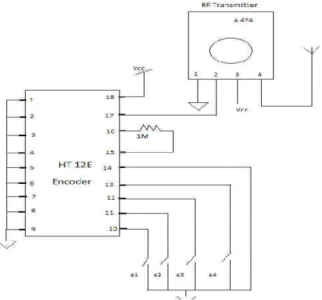
The transmitter part is built with two basic components i.e with encoder RF transmitter module and IC HT12E operates at 434 MHz as shown in Figure 2
IC has four ports which are used as input button controlling the appliances.
Fig.2.1: Remote control transmitter at block level And at the receiver side it consists of decoder
module and IC HT12D. The four output port of the decoder IC is connected to the appliances
as shown in Figure 2.2.
Fig 2.2: Receiver section with load to be controlled
When a button is pressed then the respective will be active which in turn will active the control the appliance.
Fig 2.3: Circuit connection of Remote RF transmitter
Infogainpublication.com)
IMPLEMENTATION
t with two basic components i.e IC HT12E which 2.1. The encoder input buttons for
Remote control transmitter at block level consists of decoder RF receiver
The four output port of the through a relay
Receiver section with load to be controlled
respective output port will be active which in turn will active the relay and
Circuit connection of Remote RF transmitter
The modulation technique Amplitude Shift Keying (ASK) MHz. The input data pin at the
serial data and transmits the serial data
frequency which is again picked up by the transmitter module placing at a distance.
Fig. 2.4: Schematic diagram of
This Rx/Tx module is used with two IC’s i.e de encoder each having four port
input channel and output channel.
Fig .2.5: Schematic diagram of
The encoder IC HT12E converts the parallel data serial data from the four input switches and fed the data through pin 17 into the input data pin (
transmitter module. The serial data signals are transmitted ) ISSN : 2454-1311
Page | 30 at the transmitter follows (ASK) which is operating at 434 The input data pin at the transmitter module accepts and transmits the serial data through Radio again picked up by the transmitter distance.
Schematic diagram of RF transmitter ule is used with two IC’s i.e decoder and
ports which are configured as input channel and output channel.
Schematic diagram of RF Receiver
International Journal of Advanced Engineering, Management and Science (IJAEMS) [Vol-2, Issue-3, March- 2016] Infogain Publication (Infogainpublication.com) ISSN : 2454-1311
www.ijaems.com Page | 31 through the antenna of RF transmitter module. In order to
enable the transmission, pin 14 should be connected to active low state. These set of transmitted data signal is received by the transmitter module and then fed in serially to the decoder IC HT12E through the data input pin 14 and the decoder converts the serial data again into parallel data and outputted at the four output port through D0 to D3. Each of the input switches is configured to control a corresponding relay from which a load is connected as shown in Figure 2.5.
Transmission through Radio Frequency has numerous advantages over infrared transmission. RF signal can travel a longer range hence its coverage area is larger and moreover the transmitter and receiver need not to be in line of sight. As RF frequency signal is strong, it is more reliable than infrared transmission. The RF modules used here comprises of transmitter and receiver which operates at frequncy of 434 Mhz. The data transmission takes place between pin 2 serially in each module as shown in Figure 4 & 5. The system is designed and model to control any four load.
2.1 SNAPSHOTS OF CIRCUIT
Fig. 2.6: Snapshot of transmitter circuit
Fig. 2.7: Snapshot of Receiver circuit
III. COMPONENTSANDTHEIRDESCRIPTION
3.1 COMPONENTS USED
3.1.1 RF Transmitter and Receiver 3.1.2 Microcontroller 89s52 3.1.3 Enccoder HT12 E 3.1.4 Decoder HT12 D 3.1.5 MCT 12E 3.1.6 Relay
3.1.7 Crystall Oscillator 3.1.8 Transformer
3.1.9 Capacitors, Diodes, Resistors 3.1.10 Voltage Regulator
3.2 BRIEF DESCRIPTION
3.2.1 RF Transmitter and Receiver
RF module operates at Radio Frequency and its corresponding frequency range varies from 30 kHz & 300 GHz. In this RF system, the digital data is given as variations in the amplitude of carrier wave. This kind of modulation here is known as Amplitude Shift Keying (ASK).
Fig. 3.1: RF transmitter and receiver
This RF module consists of a RF Transmitter and a RF Receiver. The transmitter/receiver pair (Tx/Rx) operates at a frequency of 434 MHz and An RF transmitter receives serial data and transmits it to antenna connected at pin 4 wirelessly through RF. This transmission occurs at the rate between 1Kbps and 10Kbps.The transmitted data is received by a RF receiver operating at the same frequency as that of the transmitter.
Infogain Publication (Infogainpublication.com) ISSN : 2454-1311
www.ijaems.com Page | 32 3.2.2 ABOUT 89S52 MICROCONTROLLER
The AT89s52 is a low-power based, high-performance 8-bit CMOS microcontroller having 8K bytes of insystem programmable Flash memory. The device is made by using Atmel’s high density non-volatile memory technology and is fully compatible with the industry standard 80c51 pin out and instruction set. The on-chip Flash allows the device memory to be reprogrammed in-system or by a usual non-volatile memory programmer. By combining versatile 8-bit CPU with in-system programmable Flash on a mono-lithic chip, the Atmel AT89s52 is a very puissant microcontroller which provides a highly-flexible and cost-effective solution to numerous embedded control applications.
The AT89s52 gives the following standard features: 256 bytes of RAM, 8K bytes of Flash, 32 I/O lines, two data pointers, Watchdog timer, three 16-bit timer/counters, on-chip oscillator, a six-vector two-level interrupt architecture,, clock circuitry and a full duplex serial port. The Idle Mode freezes the CPU while allowing the timer/counters, serial port, RAM and interrupt system to continue functioning. The Power-down mode saves the RAM contents but stops the oscillator and disables all other chip functions until the next interrupt or hardware reset.
3.2.3 ENCODER AND DECODER 3.2.3.1 HT12E Encoder
This encoder IC is integrated 2^12 series of encoders. HT12E is mainly used to interface RF circuits and IR circuits. This IC converts 12 bit parallel to serial. These 12 bits are divided into 8 address bits and 4 data bits. This IC has transmitter enable pin. When the trigger signal is received on this pin, data bits and the address are transmitted together. This IC starts a 4 word transmission cycle upon the receipt of enable. The transmission cycle is repeated unless transmitter enable is kept low.
3.2.3.2 HT12D Decoder
This decoder IC converts the serial input data into parallel data. This IC indicates valid transmission by high at Valid Transmission (VT) pin.
Decoder HT12E is capable of decoding 12bit data (4 data bits and 8 address bits). The output data remains unchanged until the new data is received. It is mostly used in RF and IR circuits. These decoders are mostly used for remote control applications such as car door alarm, burglar alarm, security system etc.
The pair of encoder and decoder which is chosen for communication should have same number of data and address bits.
3.2.4 MCT 2E
MCT 2E mainly used as an electrical isolator as protection circuit, sometimes they're called opto-isolators. Mostly opto-couplers are used to protect communication
lines.
For example, we can use opto-couplers to protect your Tx, and Rx lines between your PC and RS232, from power surge that would be harmful to our RS232, PC and chip.
3.2.5 RELAY
It is an electromagnetic device which is used to quarantine two circuits electrically and connect those circuits magnetically. Relay are very useful devices and allow one circuit to switch to another one while they are completely separate. Usually they used to interface an electronic circuit working at low voltage to an electrical circuit which is working at very high voltage. For example, a relay can make a circuit of 5V DC battery to switch a 230V AC mains circuit. Thus a small sensor circuit will be able to drive a fan or an electric bulb. A relay switch is divided into two parts: input and output. The input section has a coil which starts generating magnetic field when a small voltage is applied to it from an electronic circuit. This voltage is called operating voltage. Commonly used relays can be acquired in different configuration of operating voltages like 24V, 12V, 9V, 6V etc. The output part consists of contactors which disconnect or connect mechanically. In a basic relay they have three contactors: normally closed (NC), normally open (NO) and common (COM). At NO input state, the NC and COM are connected and Whenever the operating voltage is applied the coils of relay get energized and the COM changes contact to NO state.
Fig. 3.3: Pin diagram of Relay 3.2.6 7805 VOLTAGE REGULATOR
International Journal of Advanced Engineering, Management and Science (IJAEMS) [Vol-2, Issue-3, March- 2016] Infogain Publication (Infogainpublication.com) ISSN : 2454-1311
www.ijaems.com Page | 33
Fig. 3.4: Pin diagram of 7805 Voltage Regulator
IV. WORKING
Initially in the transmitter circuit, when the switch is ON then parallel data goes from switch to the encoder which further converts the parallel data into serial data. Then the serial data is sent to RF transmitter further which transmits this data to the receiver circuit.
And the receiver circuit will receive this data and send it to decoder which converts the serial input data into parallel data. Then it will send this data to the microcontroller and the microcontroller send this data to particular relay which it is connected and from which our load is connected.
V. CONCLUSION
Today the world is changing swiftly, and there are multiple challenges faced by us. Surely it is the knowledge through technology, which makes us to conquer them. The paper is obligatory as per university course outline. This paper is based on work done and theory gained during analysis of the topic.
The paper basically introduces working of project in details electrical appliances can easily be controlled by using a remote based on radio frequency. In our homes there are many electrical appliances and with the help of this project we can control all of them. The controlling circuit is built from RF transmitter and RF Receiver modules which are operating at certain frequency along with a encoder and a decoder with few passive components. Multiple devices can be controlled by using different receiver with different addressing modes using single remote.
VI. FUTURE SCOPE
If anyone wants to take this work to next step then it can be done by using gsm instead of using remote which is based on radio frequency. This can easily be done just by sending short sms code from a mobile handset and where it has a wider coverage area. So to control any house hold appliance from a distant place within the coverage area we will just have to send a sms. Sending a short sms code will either ON or OFF the appliances at home. All these work is carried out for the same function but in a different way and by using different technology.
REFERENCES
[1] Santosh.M.Nejakar “Wireless Infrared Remote Controller for Multiple Home Appliances” International Journal of Electrical and Electronics Research. Vol. 2, Issue 1, pp. 25-35, Month January- March 2014.
[2] Avatade P.G.2, Belgi Y.G.1, Deshmukh P.V.3, Sakhare A.M.4, Prof. Patil J.M.6 and Shinde A.J.5 “Android Based Appliances Control System” International Journal of Emerging Technology and Advanced Engineering. Vol 3, issue 12, pp. 680-682, Dec 2013.
[3] Fida Hasan Md Rafi1, Md. Manirul Islam1, Mohiuddin Ahmad1, Abu Farzan Mitul1. International Conference on Electrical, Computer and Telecommunication Engineering, pp. 510-514, 01-02 December 2012 (ICECTE2012), RUET, Rajshahi-6204, Bangladesh
[4] Mohd Helmy Abd Wahab, Norzilawati Abdullah, Ayob Control System for Smart Home Applications” Journal of Convergence Information Technology Volume 5, Number 1, pp. 34-39 February 2010.