Design and Analysis of Soft Switching Variable
Speed Drive
N. Bala Krishnan M. Sasikumar
B.E. Student B.E. Student
Department of Electrical & Electronics Engineering Department of Electrical & Electronics Engineering SNS College of Engineering Coimbatore, Tamil Nadu, India SNS College of Engineering Coimbatore, Tamil Nadu, India
G. Nivetha J. Selvakumar
B.E. Student B.E. Student
Department of Electrical & Electronics Engineering Department of Electrical & Electronics Engineering SNS College of Engineering Coimbatore, Tamil Nadu, India SNS.College of Engineering Coimbatore, Tamil Nadu, India
R. Venkatesh Assistant Professor
Department of Electrical & Electronics Engineering SNS College of Engineering Coimbatore, Tamil Nadu, India
Abstract
DC Motor plays a vital role as drives in the Automation industries. The speed of the drives needs to be controlled according to its applications. Generally the speed control of DC motors is carried out in two ways namely Armature control and Field control methods. Armature control method is adopted while the speed of the drive is below rated speed and field control method for the above rated speed. The major drawback of the conventional speed control method is more power loss. Hence the efficiency of the drive will be reduced .To overcome these power losses and improve the efficiency of the drive, a soft switch based speed control of DC drives is proposed in this project. This project is carried out to design and analyse the soft switching variable speed drive for 5 HP DC Shunt motor. Type of speed control used in proposed system is armature voltage control and the type of speed drive is SCR based chopper. The duty cycle of the chopper drive is varied by PIC Microcontroller. Soft switching variable speed drive paves the way for modernization of speed control of DC motor. The proposed method of soft switch drive will provide fine variations of speed and power loss is eliminated.
Keywords: Chopper Pwm technique
________________________________________________________________________________________________________ I. INTRODUCTION
DC motors are well known for their excellent control of speed for acceleration and deceleration. In a DC motor the power supply directly connects to the field of the motor and causes a precise voltage control which is essential for applications which need control of speed and torque. By proper adjustment of the terminal voltage the mentioned characteristic makes a DC motor controllable over a wide range of speed. The variable speed drives, till a couple of decades back, had various limitations, such as poor efficiencies, larger space, lower speeds, etc.,
However, the advent power electronic devices such as power MOSFETs, IGBTs etc., and also with the introduction of micro -controllers with many features on the same silicon wafer, transformed the scene completely and today we have variable speed drive systems which are not only in the smaller in size but also very efficient, highly reliable and meeting all the stringent demands of various industries of modern era. In this project controlling DC motor speed using Chopper as power converter is carried out. A chopper is a static power electronic device that converts fixed dc input voltage to a variable dc output voltage. Chopper systems have smooth control capability and are highly efficient and fast in response. A chopper can be used to step down or step up the fixed dc input voltage like a transformer. There are different techniques available for the speed control of DC motors. The phase control method is widely adopted, but has certain limitations mainly it generates harmonics on the power line and it also has got p.f when operated lower speeds. The second method is PWM technique, which has got better advantages over the phase control.
II. PROPOSED SYSTEM
features.In the existing system rheostat method is used to perform the speed control of DC motor. As the entire armature current passes through the external resistance, there are tremendous power losses. As armature current is more than field current, rheostat required is of large size and capacity. Speed above rated is not possible by this method. Due to large power losses the method is expensive, wasteful and less efficient. The method needs expensive heat dissipation arrangements. In this method power loss is exist and minute variations of speed cannot be achieved.To modernize the electrical machines laboratory by controlling the DC motor through Chopper drive. To design SCR based chopper to control DC motor speed. To develop controller for chopper using microcontroller. There are two scopes in this project which is hardware development and software development. For the first scope which is hardware development are two main sections and those section are:
1) To design a motor drive.
2) To design a circuit for the PIC 16F877.
For the second scope which is the software development, To develop a software using the PBasic of the PIC 16F877.
III. BLOCK DIAGRAM OF THE PROPOSED SOFT SWITCHING VARIABLE SPEED DRIVE
Fig. 1: Block diagram of proposed soft switching speed drive.
IV. CIRCUIT DIAGRAM OF THE PROPOSED SOFT SWITCHING VARIABLE SPEED DRIVE
Fig. 2: Circuit diagram of proposed soft switching variable speed drive.
V. OPERATION OF THE CIRCUIT OF SCR
This paper mainly deals with controlling DC motor speed using Chopper as power converter and PI as speed and current controller.
Introduction to Choppers
Fig. 3: Chopper
Average Voltage,
Vo = (Ton/ (Ton+Toff))*Vs (1) = (Ton/T)*Vs
= aVs Ton=on-time. Toff=off-time.
T=Ton+Toff = Chopping period. a=Ton/Toff.
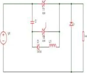
SCR based DC Chopper:
Fig 4. shows that the circuit of SCR based chopper. In a voltage commutated thyristor circuit a voltage source is impressed across the SCR to be turned off, mostly by an auxiliary SCR. This voltage is comparable in magnitude to the operating voltages. The current in the conducting SCR is immediately quenched; however the reverse-biasing voltage must be maintained for a period greater than that required for the device to turn-off. With a large reverse voltage turning it off, the device offers the fastest turn-off time obtainable from that particular device. It is an exposition of ‘hard’ turn-off where the reverse biasing stress is maximum. T1 is the main SCR and T2 isthe Auxiliary. As a consequence of the previous cycle, Capacitor C is charged with the dot as positive. When the Main SCR is triggered, it carries the load current, which is held practically level by the large filter inductance, L and the Free-wheeling diode. Additionally, the charged Capacitor swings half a cycle through T1, L and D ending with a negative at the dot. The reverse voltage may be less than its positive value as some energy is lost in the various components in the path. The half cycle capacitor current adds to the load current and is taken by the Main SCR. With the negative at the dot C-T2 is enabled to commutate T1. When T2 is triggered the negative charge of the capacitor is impressed onto T1 and it immediately turns off. The SCR does take the reverse recovery current in the process. Thereafter, the level load current charges the capacitor linearly to the supply voltage with the dot again as positive. The Load voltage peaks by the addition of the capacitor voltage to the supply when T2 is triggered. The voltage falls as the capacitor discharges both changes being linear because of the level load current. When the Capacitor voltage returns to zero, the load voltage equals supply voltage. The turn-off time offered by the commutation circuit to the SCR lasts till this stage starting from the triggering of T2. Now the capacitor is progressively positively charged and the load voltage is equally diminished from the supply voltage. T2 is naturally commutated when the capacitor is fully charged and a small excess voltage switches on the freewheeling diode. With the positive at the dot the capacitor is again ready for the next cycle. Here T2 must be switched before T1 to charge C to desired polarity. Voltage commutation may be chosen for comparatively fast switching and it can be identified from the steep fall of the SCR current. There is no overlapping operation between the incoming and the outgoing devices and both currents fall and rise sharply. Stresses on all the three semiconductors can be expected to be high here.
Working Principle
For convenience the chopper operation is divided into five modes. 1) Mode-1
2) Mode-2 3) Mode-3 4) Mode-4 5) Mode-5 Mode-1 Operation
Fig. 5: SCR Mode I
The above Fig 5. shows the circuit of SCR chopper for mode I. The operating steps is derived below, 1) Thyristor T1 is fired at t = 0.
2) The supply voltage comes across the load. 3) Load current IL flows through T1 and load.
4) At the same time capacitor discharges through T1, D1, L1, & ‘C’ and the capacitor reverses its voltage. 5) This reverse voltage on capacitor is held constant by diode D1.
Mode-2 Operation
Fig. 6: SCR Mode II
The above Fig 6.shows the circuit of SCR chopper for mode II. Operating steps are, 1) Thyristor T2 is now fired to commutate thyristor T1.
2) When T2 is ON capacitor voltage reverse biases T1 and turns if off.
3) The capacitor discharges through the load from –V to 0. Discharge time is known as circuit turn-off time 4) Capacitor recharges back to the supply voltage (with plate ‘a’ positive).
5) At the end of Mode-2 capacitor has recharged to VS and the freewheeling diode starts conducting. Mode-3 Operation
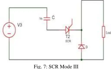
Fig. 7: SCR Mode III
The above Fig 7. shows the circuit of SCR chopper for mode III. Operating steps are, FWD starts conducting and the load current decays.
Mode-4Operation
Fig. 8: SCR Mode IV
The above Fig 8. shows the circuit of SCR chopper for mode IV. Operating steps are, 1) Capacitor has been overcharged i.e. its voltage is above supply voltage. 2) Capacitor starts discharging in reverse direction.
3) Hence capacitor current becomes negative.
4) The capacitor discharges through VS, FWD, D1 and L.
5) When this current reduces to zero D1 will stop conducting and the capacitor voltage will be same as the supply voltage Mode-5 Operation
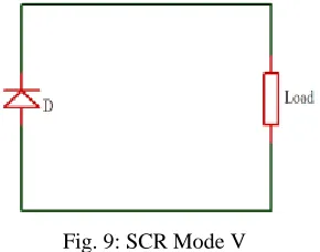
Fig. 9: SCR Mode V
The above Fig 9. shows the circuit of SCR chopper for mode V. Operating steps are, 1) Both thyristors are off and the load current flows through the FWD.
2) This mode will end once thyristor T1 is fired.
Modeling of DC motor for drive system:
An electrical DC drive is a combination of controller, converter and DC motor. Here we are using chopper as a converter. The basic principle behind DC motor speed control is that the output speed of DC motor can be varied by controlling armature voltage keeping field voltage constant for speed below and up to rated speed . The output speed is compared with the reference speed and error signal is then fed to speed controller. If there is a difference in the reference speed and the feedback speed, Controller output will vary. The output of the speed controller is the control voltage Eg that controls the operation duty cycle of converter. The converter output gives the required voltage V to bring motor speed back to the desired speed. The Reference speed is provided through a potential divider because it is linearly related to the speed of the DC motor. Now the output speed of motor is measured by Tacho-generator. The tacho voltage we will get from the tacho generator contains ripple and it will not be perfectly dc. So, we require a filter with a gain to bring Tacho output back to controller level.
it is not used. The derivative action causes the noise in the main signal to be amplified and reflected in the controller output. Hence the most suitable controller for speed control is PI type controller.
1) Select Device 2) Project wizard
3) Add files (Template, linker) 4) Build all
5) Debugging using MPLAB SIM 6) Programming using PIC START PLUS
Steps to download program in PIC microcontroller using mplab software
1) Open mplab software.
2) Select project and project wizard. 3) Choose pic16f68774 controller 4) Select complier-hitech
5) Give floder path and finish 6) Creat new source file.
7) In that space type code of project. 8) Save as extension .c
9) Source file right click and add file .c 10) Open and run (black icon)
11) Ensure that rs232 cable is connecting to dump kit. 12) Select programmer and PIC kit 2
13) Download the program in controller
14) After that kit is ready this massage will come.
POWER SUPPLY
Bridge Rectifier
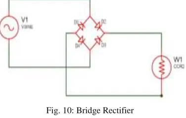
Fig 10 shows the Bridge rectifier circuit. It is used for the power supply to the PIC microcontroller. Rectifier used for conversion of an alternating current (AC) input into a direct current (DC) output is known as bridge rectifier.
Fig. 10: Bridge Rectifier
There are two operating cycles are in bridge rectifier. During first half cycle diodes D1 and D3 will conduct. During the second half cycle the diodes D2 and D4 will conduct.
VI. RESULT AND DISCUSSIONS
Speed variation of DC shunt motor is controlled using chopper drive. The different speed levels have been achieved by the speed control given by copper drive. The discussion were carried out about the results, such that the supply voltage, duty cycle, armature voltage and speed. From the discussions it have been concluded that in this proposed system the power loss of 4 Watts is eliminated and fine variations of speed is achieved.
Execution
1) STEP 1: Chopper drive has different modes.
Duty cycle,Frequency,Voltage Initially the mode has to be selected.
2) STEP 2: The regulator is varied gradually to set a duty ratio. According to the duty cycle motor speed, voltage and frequency are controlled.
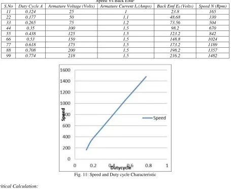
Table – 1 Speed Vs Back EMF
S.No Duty Cycle Α Armature Voltage (Volts) Armature Current Ia (Amps) Back Emf Eb (Volts) Speed N (Rpm)
11 0.124 25 1 23.8 165
22 0.177 50 1.1 48.68 330
33 0.265 75 1.2 73.56 504
44 0.35 100 1.5 98.2 670
55 0.438 125 1.5 123.2 842
66 0.53 150 1.5 148.8 1024
77 0.618 175 1.5 173.2 1189
88 0.708 200 1.5 198.2 1357
99 0.774 218 1.5 216.2 1482
Fig. 11: Speed and Duty cycle Characteristic
Theoritical Calculation: Va = Eb + IaRa
Eb = Va - IaRa Va = 25V Ia = 1A Ra =
Eb = 25 – Eb = 23.8V
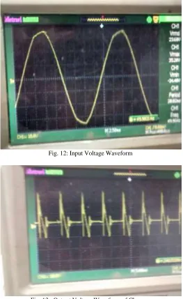
Execution Waveforms
Fig. 12: Input Voltage Waveform
Fig. 13: Output Voltage Waveform of Chopper
The above fig 13. shows the output voltage waveform of chopper. Output Voltage: 180 V, DC
Fig. 14: Duty Cycle of Chopper
Benefits of the Work
1) Power loss is eliminated.
2) A fine variation of speed is achieved. 3) There is no need of starter in this system.
4) Provides modernization of Electrical Machines Laboratory. 5) Heating problem will not occur in this system.
REFERENCES
[1] Ms.S.R.Bhagwatkar 1, Mr.A.P. Dhande2, Student, Dept. of Electronics and Telecommunication, P.R.Patil college of Engg. and Technology, Amravati, India
1, Professor, Dept. of Electronics and Telecommunication, P.R.Patil college of Engg. and Technology, Amravati,India2, A Review on Automatic Closed Loop Speed Control of a DC Motor, International Journal of Advanced Research in Computer and Communication Engineering, Vol. 4, Issue 1, January 2015.
[2] Mohd Amir Fikri Bin Awang, A Thesis Submitted in Fulfilment for the Requirement Award of the degree of, Bachelor of Electrical Engineering (Power
Systems) Faculty of Electrical and Electronics Engineering University, DC Motor Speed Controller, Malaysia Pahang November, 2010.
[3] Nurul Izzati Binti Pandak Jabo, Speed Control of DC Motor Using PID Controller Implementation with visual Basic,This thesis is submitted as partial fulfilment of the requirements for the award of the Bachelor of Electrical Engineering (Hons.) (Electronics) Faculty of Electrical & Electronics Engineering University Malaysia Pahang November, 2008.
[4] Praveen Kumar Nambisan.T.M1, Dr.B.N.Sarkar2, PG Student [Power Electronics], Dept. of EEE, Dayananda Sagar College of Engineering, Bangalore,
Karnataka, India1, Professor, Dept. of EEE, Dayananda Sagar College of Engineering, Bangalore, Karnataka, India2, Study of Speed Control of DC Series Motor Using DC Chopper International Journal of Advanced Research in Electrical Electronics and Instrumentation Engineering, vol. 3, issue 8, august 2014.
[5] K.A.Wadile1, S.R.Chillarge2, D.D.Jadhav3, Pravara Rural Engineering College Loni, Ahmednagar (M.S.), India, Speed Control and Direction Control of Dc