Comparative Study on Lateral Load Resisting
System in Tall Building
Divya C. Bhuta Umang Pareekh
PG Student Assistant Professor
Department of Structural Engineering Department of Structural Engineering
L.J. Institute of Engineering & Technology, Ahmedabad L.J. Institute of Engineering & Technology, Ahmedabad
Abstract
In this enchanting world of structure design, building with new innovative ideas most of the time it is with the sky touching height. As these structures are extended vertically they are going to with stand the lateral loads in an enormous intensity. In this paper an investigation has been carried out over a 40 storey RCC structural space frame using different lateral load resisting system used in tall buildings. These structural systems used in the study are “shear wall”, “outrigger” and “dia-grid”. Analysis has been carried out using different method of analysis for static earthquake forces, dynamic earthquake forces (response spectrum analysis and time history analysis performed under the guidelines of IS: 1893-2002 and IS: 800-2000 respectively) and static wind forces. This will help to understand the behaviour of the mentioned lateral load resisting systems under dynamic load effect. The basic modelling technique and assumption are made by using ETABS 15.2.0 and other consideration are made according to the Indian Standard. A comparison of the top storey displacement, storey drift of the frame and the time period of the whole structure is done for different configuration of lateral load resisting systems. At the completion of the study the conclusion will be arrived and stated regarding to the effect of seismic load application.
Keywords: Tall buildings, Structural system, Dynamic analysis, ETABS, Outrigger, Dia-grid
________________________________________________________________________________________________________
I. INTRODUCTION
In today’s world tall buildings are becoming more and more slender, which leads to possibility of more sway comparing to older tall buildings. Which have made engineers to think very seriously about the effect of lateral load which will effect through its height and also an improvement needed in the use of frame structural system. The selection and arrangement of the structural system will efficiently resist more gravity and horizontal load. Selection of structural system depends on the planning, material, external architectural treatment, nature and magnitude of horizontal loading and the height of the building.
Selecting an appropriate structural system after studying many interactive design with other buildings to carry out any tall building project successfully. Once its selected is geometry has to be properly selected as lateral shear force, overturning moments induced due to the lateral load which significantly influence the structural design of tall building. When primary structural are located at perimeter, then system’s efficiency can be maximized.
The few structural systems used for the Tall Buildings are: 1) Shear wall system
2) Outrigger system 3) Dia-grid system Shear Wall System
RC buildings often have vertical plates like RC wall called shear wall in addition to slabs, beams and columns. Shear wall generally starts at foundation level and are continued throughout the building height. Shear walls are like vertically oriented wide beams that carry earth quake loads downward to the foundation. Most RC buildings with shear wall also have columns. Since shear wall carry large horizontal earth quake forces the overturning effect on them are large.
Outrigger System
Outrigger beams between the shear wall and exterior column is often provided to achieve sufficient lateral stiffness of the structure. Outrigger beams connected to the shear wall and external columns are relatively more complicated and the performance of such coupled wall systems depends primarily on adequate stiffness and strength of outrigger beams. Therefore, overall rigidity is imperative in tall buildings in order to control lateral deflection and inter-storey drift.
Dia-Grid
deformation because they carry lateral shear by axial action of dia-grid member. It provides alternate load path in the event of a structural failure and also reduce weight of the super structure can translate into a reduced load on foundation.
II. OBJECTIVES
To analyse the lateral load resisting system and comparing several systems in tall buildings.
Comparing the behaviour of structures for static and dynamic earthquake analysis for different lateral load resisting system i.e shear wall, outrigger and dia-grid, and by comparing different parameters such as 1.) Lateral displacement 2.)Base shear 3.)Story drift 4.)Modal Time Period.
III. ANALYSIS
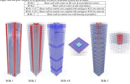
Analysis of structure is done using ETABS 15.2.0. The models were prepared in the ETAB S. Software by using different structural system with different positing of shear wall viz. at centre of side of periphery and at corner of periphery, different location of outrigger and dia-grid. Models to be generated wit above structural system are as under.
M-Sh.1 Shear wall with center as lift core & at peripheral corners M-Sh.2 Shear wall at center of side of periphery
M-Or. 3-15 Shear wall at central core coupled with outriggers @11 stry interval M-Or. 4-10 Shear wall at central core coupled with outriggers @10 stry interval
M-Br. 5 Shear wall at central core with bracing at periphery
Fig. 1: Models with different structural system
IV. PROBLEM FORMULATION
For the analysis purpose, the model of RC building of G+40 storeys and 34mx34m plan area has been selected. Model Data
Description 40 - Storey Material
Thickness of lift core 550 mm M40
Thickness of shear wall 300 mm M40
Depth of Outriggers 2 storey N.A.
No of Outriggers 3 and 4 N.A.
Intervals of Outriggers 10 storey and 15 storey N.A.
Outrigger Section ISNB350H Fe345
Bracing Section ISNB350H Fe345
Frame Property
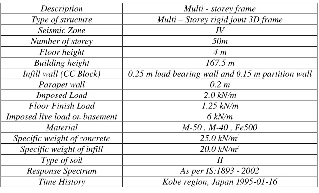
Description Multi - storey frame
Type of structure Multi – Storey rigid joint 3D frame
Seismic Zone IV
Number of storey 50m
Floor height 4 m
Building height 167.5 m
Infill wall (CC Block) 0.25 m load bearing wall and 0.15 m partition wall
Parapet wall 0.2 m
Imposed Load 2.0 kN/m
Floor Finish Load 1.25 kN/m
Imposed live load on basement 6 kN/m
Material M-50 , M-40 , Fe500
Specific weight of concrete 25.0 kN/m3
Specific weight of infill 20.0 kN/m3
Type of soil II
Response Spectrum As per IS:1893 - 2002
Time History Kobe region, Japan 1995-01-16
V. ASSUMPTION MADE FOR MODELLING
Base Shear
The base shear is obtained for the lateral force of earth quake, response spectra and time history component in X & Y direction. As the building is symmetrical in both in plane direction.
Top Storey Displacement
The upper most node of the structural frame on the right side of the frame in plane frame xz-section and yz-section, the top storey displacement has been considered for each of the lateral X directional force due to earth quake, response spectra and time history forces.
The geometry for all of the model frames is considered same. The column sizes reduce accordingly throughout the building height at regular intervals of storey number. As shown in the geometry there are three different column sizes in plan. The all members of outrigger truss and dia-grid are restricted to withstand the axial forces only; no moments or torsion action is allowed to transfer thought these members hence they are given a pin joints at the both ends of the members. The bottom of ground floor columns is connected with ground and are given fixed joint restrain as it is assumed to be rigidly connected with the ground.
Table – 1
Assumption for column and beam size Beam
Column Storey G+40
Plinth 300X600 G+40
1 to 10 450X950 1 to 10 1200X1200 1000X1000 900X900
11 to 20 375X950 11 to 20 1050X1050 850X850 750X750
21 to 31 375X900 21 to 31 900X900 700X700 600X600
31 to 40 350X650 31 to 40 750X750 550X500 450X450
VI. ANALYSIS METHOD AND PARAMETERS
Equilateral Force Method
This method is performed as per IS: 1893 – 2002 with help of software. The mass source is defined to consider seismic weight of building frame as dead load and particular amount of live load i.e. Dead Load + 0.25 (Live Load).
Fundamental time period is taken as Tn = 0.09*h / √D
Tn=2.51 R = 4% I = 1.0
Response Spectrum Method
This method is applied along the code specifications of IS: 1893 – 2002 with considering the modal combination method of Square Root of Sum of Square Method.
Function Damping ratio = 0.05 Z = 0.24
Initial Scale Factor (I.S.F.) = I/2 * g/R = (1/2 *9.81 /4) = 1.22 Final Scale Factor (F.S.F.) = I.S.F. * (VB / V̅B)
Time History Method
In this method transient time history of Kobe Region is taken to perform time history analysis. Initial condition of process is considered as unstressed state at time t = 0 sec.
Modal Damping ratio = 0.05 Number of output steps = 1200 Output step size = 0.02 sec
Initial Scale Factor (I.S.A. = Z/2 * g/R = 0.24/2 9.81* /4 = 0.2943
Final Scale Factor (F.S.F.) = (I.S.F.) * (VB / V̅B)
VII. RESULTS
Results for G+40 storey is calculated for a for a given parameter i.e. Base Shear, Lateral displacement, Storey Drift, Modal Time Period.
Base Shear
Table – 2 Base Shear in X (kN)
Method of analysis M-Sh.1 M-Sh.2 M-Or. 3-15 M-Or. 4-10 M-Br. 5
Seismic analysis 10122.18 10078.20 9963.19 9966.12 9829.88
Response spectrum 10122.18 10078.20 9963.19 9966.12 9838.41
Time history 10121.96 10077.99 9963.19 9966.12 9829.88
Table – 3 Base Shear in Y (kN)
Method of analysis M-Sh.1 M-Sh.2 M-Or. 3-15 M-Or. 4-10 M-Br. 5 Seismic analysis 10122.18 10078.20 9963.19 10059.00 10248.82 Response spectrum 10122.18 10077.99 9963.19 10059.00 10248.82 Time history 10122.42 10078.20 9963.70 10059.00 10248.82
Top Storey Displacement
Table – 4
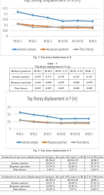
Top Storey displacement in X (m)
Method of analysis M-Sh.1 M-Sh.2 M-Or. 3-15 M-Or. 4-10 M-Br. 5
Seismic analysis 0.189 0.166 0.135 0.139 0.134
Response spectrum 0.098 0.087 0.075 0.076 0.073
Fig. 2: Top storey displacement in X
Table – 5
Top Storey displacement in Y (m)
Method of analysis M-Sh.1 M-Sh.2 M-Or. 3-15 M-Or. 4-10 M-Br. 5
Seismic analysis 0.195 0.171 0.138 0.143 0.141
Response spectrum 0.104 0.090 0.078 0.080 0.079
Time history 0.095 0.085 0.085 0.088 0.088
Fig. 3: Top storey displacement in Y
%reduction in top storey displacement of outrigger, dia-grid with respect to M-Sh.2 in X Direction
M-Or4.8 M-Or4.10 M-Br.5
Seismic analysis 28.28 % 26.10 % 28.74 %
Response spectrum 23.19 % 22.06 % 25.37 %
Time history 3.85 % 3.25 % 2.04 %
%reduction in top storey displacement of outrigger, dia-grid with respect to M-Sh.2 in Y Direction
M-Or4.8 M-Or4.10 M-Br.5
Seismic analysis 29.25 % 26.69 % 27.63 %
Modal Time Period
Table – 6 Modal time period
M-Sh.1 M-Sh.2 M-Or. 3-15 M-Or. 4-10 M-Br. 5
4.254 3.971 3.64 3.693 3.617
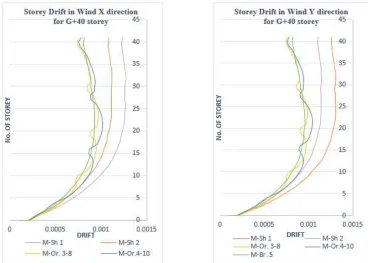
Storey Drift
Fig. 4: Storey Drift in EQ X and EQ Y direction
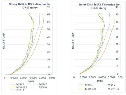
Fig. 6: Storey Drift in RS X and RS Y direction
VIII. CONCLUSION
The % difference of lateral displacement is more in seismic co-efficient method and lesser in response spectrum method. While using dia-grid system, model shows the minimum displacement in comparison to other models in time history analysis. Overall drift reduces in outrigger system compared to other system.
Fluctuation in drift is observed where the outrigger are connected to the core.
REFERENCES
[1] P. Jayachandran, Ph.D, M.Asce, “Design of tall buildings preliminary design and optimization” National Workshop On High Rise And Tall Buildings, University Of Hyderabad, Hyderabad, India, May 2009, Keynote Lecture.
[2] Bis (2000) Is 456: 2000, “Indian Standard Plain and Reinforced Concrete - Code of Practice (Fourth Revision)”, Bureau of Indian Standards Ics 91.100.30. [3] IS 1893: 2002 “Indian Standard Criteria for Earthquake Resistant Design of Structures” Part 1 General Provisions and Buildings (Fifth Revision) Ics 91.120.25
criteria for Earthquake Resistant Design Of Structures
[4] Kyoung-Sun Moon1, Jerome J. Connor and John E. Fernandez, “Dia-grid Structural Systems for Tall Buildings: Characteristics and Methodology for Preliminary Design”, Wiley Inter Science Doi:10.1002/Tal.311
[5] IS: 875(Part-I, II, III)-1987, “Code of Practice for Design Loads (other than Earthquake) for Buildings and Structures”, Bureau of Indian Standard, New Delhi.