Article
From Undesired Flaws to Esthetic Assets: A Digital
Framework Enabling Artistic Explorations of
Erroneous Geometric Features of Robotically
Formed Molds
Malgorzata A. Zboinska
Department of Architecture and Civil Engineering, Chalmers University of Technology, SE-412 96 Gothenburg, Sweden; [email protected]
Received: 28 September 2019; Accepted: 30 October 2019; Published: 31 October 2019
Abstract: Until recently, digital fabrication research in architecture has aimed to eliminate manufacturing errors. However, a novel notion has just been established—intentional computational infidelity. Inspired by this notion, we set out to develop means than can transform the errors in fabrication from an undesired complication to a creative opportunity. We carried out design experiment-based investigations, which culminated in the construction of a framework enabling fundamental artistic explorations of erroneous geometric features of robotically formed molds. The framework consists of digital processes, assisting in the explorations of mold errors, and physical processes, enabling the inclusion of physical feedback in digital explorations. Other complementary elements embrace an implementation workflow, an enabling digital toolset and a visual script demonstrating how imprecise artistic explorations can be included within the computational environment. Our framework application suggests that the exploration of geometrical errors aids the emergence of unprecedented design features that would not have arisen if error elimination were the ultimate design goal. Our conclusion is that welcoming error into the design process can reinstate the role of art, craft, and material agency therein. This can guide the practice and research of architectural computing onto a new territory of esthetic and material innovation.
Keywords: digital fabrication; digital design; robotic single-point incremental forming; fabrication errors; imprecision; material agency; artistic architectural computing; esthetic design exploration
1. Introduction
1.1. Background
In contemporary experimental architectural design, industrial robots are included in the design process as a medium of accessing the physical phenomena accompanying the processing of architectural materials. Architectural programming, computing, and customized robotic fabrication have now become vehicles for design innovation. The inclusion of robotic fabrication into the design pipeline has interestingly extended the abstract realm of digital experimentation in computer-aided architectural design (CAAD) onto the physical territory.
A general observation of digital fabrication as a research area in architecture leads to the conclusion that it has been heavily focused on achieving geometrical accuracy [1]. Such a focus has generated vast knowledge on fabrication error elimination and computational control of material behaviors. Architectural studies of this research trajectory developed versatile computational methods of increasing geometrical accuracy in materialized designs, to fulfill the esthetic criterion of perfectly engineered beauty [2].
Likewise, the manufacturing of molds and free-form shapes with high accuracy is a well-studied problem in engineering research supporting architectural fabrication. Considerable work in the area of architectural geometry has been done to develop efficient strategies of paneling and optimizing non-standard architectural shapes to manufacture them at a reasonable cost and with the desired aesthetic quality [3–5]. A vast body of research has also yielded methods of geometrical optimization of machine toolpaths to increase the geometric accuracy of double-curved elements, molds, and dyes [6,7]. Our study explores an alternative approach to this exactness-oriented and computationally accurate handling of fabrication errors. This approach regards geometrical errors as esthetic traits and welcomes computational imprecision as a generative factor in the design process. We develop a framework that facilitates the implementation of such an approach in the computational design and digital fabrication process. Our framework departs from the tradition of error elimination towards its creative, artistic exploration.
1.2. Motivation and Significance
This study is focused on fabrication errors in robotic single-point incremental forming (SPIF) of polymer sheets, for several reasons. Firstly, because this fabrication method is promising from the standpoint of wider applications in the architectural industry. It enables materialization of highly-customized, non-repeatable architectural elements by means of molding and casting. Such elements can embrace external façade panels, decorative interior cladding, or furniture at urban, landscape, and interior architecture scale. A wide range of materials can be cast into the robotically formed molds, from concrete and plaster to biomaterials such as mycelium and bioplastics, or even more unconventional materials, such as silicone. This versatility of applications and materials suggests the significance of investigating in this fabrication method in the context of non-standard manufacturing of architectural elements [8].
The second motivation, tied to the first one, arises from the sustainability and economic benefits of polymer SPIF as a method of building element production. Polymer molds can be easily reused or repurposed through recycling. Further, their production does not require the use of dyes. The production of a custom dye for each non-repeating mold design would be inefficient and time-consuming. It would create an additional cost but also generate considerable material waste due to the subtractive methods used in dye production. Because dye-less SPIF has already proven to be sustainable and material-efficient [9], it is now important to investigate its further benefits, oriented towards design and esthetic qualities.
This relates to the third motivation of the study, linked to the esthetic design potential of polymer SPIF. Forming of polymers exhibits a good capacity to influence the final design expression. The high elasticity and plasticity of polymers causes material deformations upon forming that are much more unpredictable than in the case of their alternative—metals [10]. The high material instability of polymers increases the level of geometrical imprecision of the fabricated molds and therefore creates interestingly challenging conditions to work within. In this way, it provides an incentive for explorative material research at the artistic level of architectural design.
Fourthly, undertaking this study is significant for filling some particular knowledge gaps in contemporary architectural research—both in digital fabrication research in general, and in robotic SPIF research in particular—as discussed below.
1.3. Knowledge Contribution to Architectural Computing and Digital Fabrication
Another example of increased interest of the CAAD community in erroneous processes is a strand of research on architectural three-dimensional (3D) printing that pushes the boundaries of computation in a way expressed at the ACADIA conference. Here, a number of studies emerged that developed methods of 3D printer code manipulation and physical 3D printer setup customization that turn the typical errors accompanying 3D printing into unique esthetic features [14–16].
Single studies can also be identified in general digital fabrication research, examining errors as well as unpredictable material behaviors accompanying other fabrication methods, such as robotic extrusion of ferrofluids [17], gravity printing [18], glass slumping [19], vacuum forming [20], and reconfigurable molding [21]. This study collection presents how material behaviors can be steered computationally to determine the esthetic appearance of the design.
To conclude, the research referenced above takes the perspective of computational control of material processes. An opposite approach, featuring intuitive and imprecise exploration of material behaviors within the framework of computation, remains yet to be developed. Our ambition with the undertaken research was to contribute to filling this knowledge gap, by providing a framework exemplifying such an approach in the context of robotic fabrication using the SPIF method.
1.4. Knowledge Contribution to Architectural Robotic SPIF
In the specific context of architectural SPIF research, our first contribution concerns the function of architectural elements explored in research. To our knowledge, the majority of studies discussed the immediate production of architectural elements. Elements such as façade panels and footbridge components were the subject of investigations [22,23], but not architectural molds from which architectural elements can be cast using other materials. Our investigation of architectural mold fabrication therefore adds a new component to this body of knowledge.
Our second contribution pertains to the purpose of previous studies on architectural SPIF. So far, their aim was to develop methods that increase the geometrical precision of the formed elements [24,25]. Therefore, they leave the aspects of error exploration undisclosed. In this context, we contribute with an approach based on the notion of desired fabrication errors.
Our third contribution relates to the materials investigated in architectural SPIF. The previous studies, as referenced above, investigated the forming of metal as the primary material. Only one study discussed the forming of polymers and its potentials for wider implementation in architecture [26]. Importantly, this study also argued that the typical polymer forming error of surface micro-cracking could be explored as a design asset. However, that notion was only discussed briefly and not further developed. Our contribution, herein, expands the sparse existing knowledge on architectural SPIF of polymers by providing a novel standpoint of geometrical error exploration for esthetic design purposes.
1.5. Main Aims and Highlights of the Work
Prompted by the abovementioned state of knowledge, we developed a digital framework that enables explorations of erroneous geometric features of robotically formed polymer sheets, in a way that introduces artistic intuition and ambiguity into the conventionally precise computational environment. Through the construction of such a framework, we sought to add to the still young research on imprecision in computation with new knowledge pertaining to alternative approaches employing imprecision and fabrication errors as design drivers.
A general conclusion suggested by our study is that welcoming into the computational process both the imprecise actions of the human designer and the unpredictable agency of materials brings with itself the capacity to reinstate the role of art and craft in architectural computing. By revealing the value of creative processing of material behaviors, it can alter the prevalent esthetic convention of the perfectly engineered architectural object and initiate the emergence of a new esthetic canon of imperfect beauty, signified by the joint agency of designers, materials, and digital fabrication machines.
to a refreshing conclusion that digital fabrication does not always need to strive for physical instances perfectly mirroring the digital models to be meaningful from the design standpoint. The material errors perceived as generative rather than disruptive can liberate computational designers from geometrical perfection as the only viable design goal, and expand their focus onto the exploration of new esthetic forms and new material expressions.
1.6. Product Imperfection and Potential Areas of Its Application
To describe a product with imperfections viewed in positive light, we adapt its established definition from industrial design [27]. Consequently, we define imperfections as geometrical and/or surficial deviations of the product from the original design model. These imperfections result from particular ways of mechanical processing of materials and can be influenced to emerge in a certain way. Importantly, these imperfections should not compromise the global functionality or quality of a product. For example, elements that are parts of assemblies may still need to comply with the requirement of a dimensionally precise geometrical border that enables their accurate fitting. Therefore, the imperfections of interest embrace tolerated errors within the product’s form and surface finish that do not hinder the production of standard products [28,29].
Potential areas of application for products with imperfect features, as defined above. include art and sculpture, architectural design, interior design, furniture design, and landscape furniture design. Particular product examples could embrace ornamental façade panels, decorative interior cladding elements, and sculptural elements such as pillars and free-standing furniture pieces. For these products, the exactness of shape at the level of surface design or form detail design may not be the main criterion for quality assessment, leaving room for the introduction of artistically explored imprecisions that do not disrupt the overall functionality of the product. Our approach will suit well cases in which the client orders a solution with a certain function but leaves the esthetic design expression to its creator. Especially in architectural design, clients often do not order a particular shape or exact geometrical design, which leaves room for the creative exploration of error that does not compromise the quality of the product.
In the context of client expectations, it is also important to mention user experience research, which indicates that people experience materials and products very differently [30]. Thus, imperfections may be perceived as faulty or incomplete by some, while for others, they appear unique or original [31]. This entails that the possibility of introducing imperfection as a driving element of design should be considered at the earliest stages of design planning, in which client expectations are established.
Another matter to consider is that irregularities on material surfaces or within the material mass, as defined above, could improve the functionality of a product [27,32]. For example, an imperfect surface finish in the form of a porous texture may have a positive acoustic effect of sound damping. Likewise, uneven material distribution in cast building elements resulting in thicker areas may locally increase their loadbearing capacities or even their thermal properties by creating material accumulations in which thermal energy can be stored and perhaps repurposed in some way. This could lead to very pragmatic applications in which the emergence of manufacturing flaws is intentionally guided to improve the functional properties of the manufactured design. It could also positively affect sustainability and resource efficiency in production by contributing to a reduced number of products that are discarded due to material or surficial flaws [27].
feature some irregularities in material settling, which do not affect functionality while embedding unique esthetic traces of the material process in the final product [15].
Therefore, the notion of manufacturing errors as viable features is already recognized to some extent in design. At the same time, in architectural design, it is a quite novel concept. Even though it has already been put forth [36], it still resides within the realm of experimental practice. That is, because it necessitates the development of new design agendas and methodologies that considerably depart from current paradigms and conventions. Therefore, it will certainly take time for the architectural practice, the building element manufacturing industry, and the construction sector to fully legitimize and adopt it as a viable design possibility.
1.7. Positioning of the Study in the Contexts of CAAD and Building Information Modeling (BIM)
Traditional 3D CAAD is based on direct modeling of surfaces, with users needing to edit every feature of a geometrical object manually. Rhinoceros®3D is an example of a common architectural software for direct modeling, supporting the creation of complex, non-standard, free-form building components. Traditional architectural BIM, on the other hand, relies on object-based parametric modeling. Therein, instead of direct 3D modeling of each building element from discrete surfaces, the designer uses a generic 3D model, often predefined. Its parameters are changed to generate particular 3D instances whose properties are automatically updated within the entire model upon each parameter change. A commonly used BIM program in architecture is Autodesk®Revit®, applied in the modeling of architectural elements with standard geometry, accompanied by automated extraction of information describing the features of those elements.
In comparison with the above systems, however, our work addresses yet another type of 3D modeling methods—advanced associative parametric modeling using visual scripting. This modeling approach extends the standard functionalities of both CAAD and BIM programs. Through a modular programming approach, it enables the creation, extraction, and processing of parametric surface data in geometrically complex CAAD and BIM models. For CAAD, a popular add-in is Grasshopper® for Rhinoceros®, which enables to parameterize standard 3D models of surfaces and control them using geometrical associations, parameters, and mathematical formulae. For BIM, a popular add-in is Dynamo®for Revit®, which enables designers to move beyond the use of standard predefined building components, and work with non-standard, free-form surface models that can be linked into the main building model and endowed with typical BIM information.
In this study, we explored geometrical errors of molds within the framework of the CAAD modeler Rhinoceros®, with extended parametric modeling functionalities through visual scripting in Grasshopper®. However, our approach to error exploration could have been executed within a BIM system as well, by using the visual scripting functionalities of Dynamo®within Revit®. The BIM implementation of our framework would have been similar in workflows to the one presented in this study, with a possible difference lying in the method of erroneous mold feature evaluation. That is, given that currently no readily available add-ins for mesh analysis for Dynamo®exist, the curvatures of the erroneous mold features would need to be defined and color-coded from scratch by the user. A separate study presenting in detail such an application within the BIM context could be of great use for the broadening of knowledge and the scope of applications of our proposal, and perhaps for yielding new research questions.
2. Materials and Methods
2.1. Investigation Method
article, we focus on presenting the details of the proposed exploration framework and important prerequisites of its implementation.
2.2. Materials
For mold forming, a polymer material, i.e., polyethylene terephthalate (PET-G), was used. PET-G sheets of size 125×125 cm, 2 mm thick were formed. The coating of the formed molds enabling digital photography was done using removable rubber paint. The material cast into the mold to produce the final design objects was a translucent addition-cure silicone, colored using pigments of varying hues.
2.3. Software
The software supporting the developed framework embraced: Rhinoceros® (version 6) for free-form modeling, Grasshopper®add-on (version 1.0.0007) for visual programming, Mesh Curvature add-on for mesh analyses, KUKA|prc add-on (version 2, 31 March 2016) for robot programming, Adobe Photoshop® (version CC 2015, 2 January 2015 release) for artistic digital painting, and Autodesk® ReCap™Photo (version 19.1.0.10) for photogrammetric 3D mesh reconstruction.
2.4. Hardware
The hardware used included: For mold forming—an industrial robot arm KUKA KR150; for digital photography of the silicone casts and photogrammetry of the molds—a digital 5 megapixel camera with a 3.85 mm f/2.8 lens, in-built in Apple iPhone 4; and for silicone application onto mold—a Nuair Herkules air compressor and a pneumatic air spray gun.
2.5. Robotic Process Setup
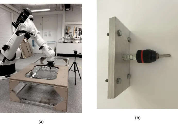
The physical setup for the forming process is shown in Figure1. The setup included a floor-mounted robot arm accompanied by frames for holding and supporting the processed material. The PET-G sheet to be formed was point-mounted between two custom-designed MDF frames with cutouts following the outline of the formed geometry. The MDF frames were mounted horizontally onto an aluminum frame. Figure1also shows the robot arm’s end effector, comprising a round-tipped metal rod, mounted in a chuck.
Technologies 2019, 7, x 6 of 22
2.2. Materials
For mold forming, a polymer material, i.e., polyethylene terephthalate (G), was used. PET-G sheets of size 125 × 125 cm, 2 mm thick were formed. The coating of the formed molds enabling digital photography was done using removable rubber paint. The material cast into the mold to produce the final design objects was a translucent addition-cure silicone, colored using pigments of varying hues.
2.3. Software
The software supporting the developed framework embraced: Rhinoceros® (version 6) for free-form modeling, Grasshopper® add-on (version 1.0.0007) for visual programming, Mesh Curvature add-on for mesh analyses, KUKA|prc add-on (version 2, 31 March 2016) for robot programming, Adobe Photoshop® (version CC 2015, 2 January 2015 release) for artistic digital painting, and Autodesk® ReCap™ Photo (version 19.1.0.10) for photogrammetric 3D mesh reconstruction.
2.4. Hardware
The hardware used included: For mold forming—an industrial robot arm KUKA KR150; for digital photography of the silicone casts and photogrammetry of the molds—a digital 5 megapixel camera with a 3.85 mm f/2.8 lens, in-built in Apple iPhone 4; and for silicone application onto mold— a Nuair Herkules air compressor and a pneumatic air spray gun.
2.5. Robotic Process Setup
The physical setup for the forming process is shown in Figure 1. The setup included a floor-mounted robot arm accompanied by frames for holding and supporting the processed material. The PET-G sheet to be formed was point-mounted between two custom-designed MDF frames with cutouts following the outline of the formed geometry. The MDF frames were mounted horizontally onto an aluminum frame. Figure 1 also shows the robot arm’s end effector, comprising a round-tipped metal rod, mounted in a chuck.
(a) (b)
Figure 1. Elements of the robotic process setup: (a) Robot arm and system of frames holding the formed material; (b) The forming tool.
3. Result Part 1—The Framework Enabling Artistic Explorations of Forming Errors
3.1. Specification of the Explored Errors
The mold errors of interest for this study are coined in manufacturing engineering literature as pillows or bulges [38]. They concern the bottom parts of the formed geometry and appear as zones with concave curvature. Such errors arise in a particular geometrical situation where curvature changes from steep to more flat. This geometrical condition generates material compression and local thickening of the material in flatter areas, elevating them as bulges. The effect is additionally amplified by the more steep and therefore stiffer neighboring zones, which push the less formed material towards the middle and then upwards [39]. The mechanics of this phenomenon are not yet fully understood but its probable cause is the in-plane stresses, in horizontal plane perpendicular to the tool axis, generated during forming [40].
The mathematical quantification of this error can be done in two ways, both of which require the reverse engineering of the physical model into a digital representation to compare the deviations between the original geometry and the physical version. One way is to express the error as orthogonal distance between the ideal geometry profile and the actual one [41]. Another way is to calculate changes in principal curvature for local error quantification [42] and aggregate normal vectors for global error quantification [43].
In our case, however, we do not apply the numerical quantification of the error. Our approach to error exploration relies on the mean curvature analysis of the fabricated geometry using an existing software tool that is commonly available to architects. Therefore, we do not employ any numerical comparisons between the original and the manufactured model as this would require creating a new analysis tool. Nonetheless, such an approach could be implemented as an interesting further development of our current research.
3.2. Generalized Workflow for Framework Implementation
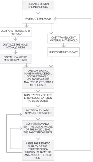
As introduction to the framework’s presentation, let us begin with an outline of a generalized workflow for the framework’s implementation. As presented in Figure2, such a workflow features a combination of physical and digital activities and is looped to facilitate design iteration.
The exploration process begins with the 3D modeling of a of a NURBS (non-uniform rational basis spline) patch surface representing the first mold design. Then, section NURBS curves are generated for the surface and approximated to define a single polyline toolpath for the robot using the workflow described in Section4.3. The mold design is then fabricated. In the next step, the fabricated mold is digitalized, i.e., reconstructed into a digital 3D representation using the photogrammetry technique. To enable digital photography for photogrammetry, one surface of the transparent and glossy polymer mold is coated with an opaque, matte, removable spray paint.
Once the photographs of the mold are complete, they are used by the photogrammetry software to generate a digital representation of the mold as a point cloud. Using in-built functions in the photogrammetry software, the point cloud is approximated into a triangular mesh representation using binary STL meshing with no decimation.
The resultant triangular mesh is imported into a 3D modeling software and its face count is reduced by 50% for faster processing. This reduced mesh is then subjected to a curvature analysis targeting the mean curvature in order to identify areas of abrupt surface curvature change and to locate mesh areas that are convex, flat, and concave. The curvature values are represented as a colored map on the mesh surface, which aids their intuitive perception.
In parallel, optionally, translucent pigmented material is cast into the mold. The translucent material’s varying accumulations indicating the erroneous features of the mold are then photographed using a digital camera.
as bases for locally affecting the erroneous mold features through combined intuitive digital painting and computational explorations.
As a result of the process, an iteration of the first mold design is generated. This 3D model is used as a point of departure for a new robot toolpath generation. The second mold is fabricated based on the toolpath data. The process of iterating its erroneous geometry features is then repeated according to the looped procedure outlined above.
Technologies 2019, 7, x 8 of 22
As a result of the process, an iteration of the first mold design is generated. This 3D model is used as a point of departure for a new robot toolpath generation. The second mold is fabricated based on the toolpath data. The process of iterating its erroneous geometry features is then repeated according to the looped procedure outlined above.
Figure 2. Generalized workflow for framework implementation.
3.3. Framework Overview
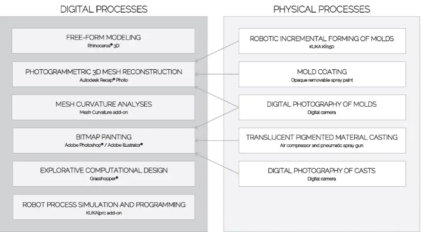
Figure 3 shows the configuration of the proposed framework for erroneous feature exploration. The framework consists of two linked components: Digital processes and physical processes.
3.3. Framework Overview
Figure3shows the configuration of the proposed framework for erroneous feature exploration. The framework consists of two linked components: Digital processes and physical processes.Technologies 2019, 7, x 9 of 22
Figure 3. Framework configuration.
3.4. Digital Processes
The digital processes component contains the digital operations assisting the explorations of geometrical errors of the robotically formed molds. The operations embrace: Free-form modeling, explorative computational design, bitmap painting, photogrammetric 3D mesh reconstruction, mesh curvature analysis, robot process simulation, and programming. Table 1 summarizes the particular functionalities of the digital toolkit enabling these operations in relation to error exploration.
The first type of operation, embracing free-form modeling, supports the creation of the first design that underpins the erroneous feature explorations. Moreover, these operations allow for the processing of the meshes obtained through photogrammetry, the fine-tuning of the intentionally erroneous mesh deformations generated based on bitmap painting, and, finally, the creation of geometries used as bases for robot toolpath programming. All of these operations are enabled by a 3D modeler Rhinoceros®, featuring a wide array of relevant tools for geometry edition, such as
NURBS surface generation, remodeling, slicing, and joining; mesh smoothing, reduction, and subdivision; as well as operations of NURBS-to-mesh conversions. The designer can carry out the operations from this group in an intuitive manner, even though in-built computation and automated algorithms of the 3D modeling software lie at their core.
Table 1. Digital toolkit functionalities in the context of error exploration.
Digital Tool in the Framework Functionality Supported Type of
Explorations
3D modeler Error design + fine-tuning Intuitive Visual program editor Error execution + exploration +
fine-tuning Intuitive + computational Mesh curvature analysis tool Error evaluation Computational
Photogrammetric mesh
reconstruction tool Error reconstruction Computational Bitmap painting tool Error design Intuitive
The second type of operation—photogrammetric 3D mesh reconstruction—facilitates the creation of a digital representation of the physical mold. Such a representation can have several purposes. Firstly, it can enable digital comparisons between the geometry of the original 3D model
Figure 3.Framework configuration.
3.4. Digital Processes
The digital processes component contains the digital operations assisting the explorations of geometrical errors of the robotically formed molds. The operations embrace: Free-form modeling, explorative computational design, bitmap painting, photogrammetric 3D mesh reconstruction, mesh curvature analysis, robot process simulation, and programming. Table 1summarizes the particular functionalities of the digital toolkit enabling these operations in relation to error exploration.
Table 1.Digital toolkit functionalities in the context of error exploration.
Digital Tool in the Framework Functionality Supported Type of Explorations
3D modeler Error design+fine-tuning Intuitive
Visual program editor Error execution+exploration+
fine-tuning Intuitive+computational
Mesh curvature analysis tool Error evaluation Computational
Photogrammetric mesh
reconstruction tool Error reconstruction Computational
Bitmap painting tool Error design Intuitive
manner, even though in-built computation and automated algorithms of the 3D modeling software lie at their core.
The second type of operation—photogrammetric 3D mesh reconstruction—facilitates the creation of a digital representation of the physical mold. Such a representation can have several purposes. Firstly, it can enable digital comparisons between the geometry of the original 3D model and of the fabricated mold. Secondly, it can serve as input for further design iterations of the mold or as a visual guide for intuitive digital bitmap painting. In our framework, the digital representation of the mold is generated using the Autodesk®ReCap™Photo software. A 3D mesh model of the mold is created from a series of digital photographs of the mold, taken at different distances, heights, and angles.
The operations of mesh curvature analyses aid the visual evaluations of the photogrammetrically digitalized molds, helping to locate their erroneous features. These operations additionally support the artistic assessment of mold fine-tuning results in each design iteration. They help to determine whether a particular fine-tuned geometry version is esthetically satisfactory or whether its fine-tuning should continue. The curvature analysis is enabled by an add-on for Grasshopper®called Mesh Curvature. The add-on visually evaluates approximate mesh curvatures—Gaussian, mean, minimum, maximum, absolute, and root mean square (RMS). The tool generates a color-coded visual representation directly on the evaluated surface, indicating which of its regions are synclastic, neutral, and anticlastic.
The operations of bitmap painting support the intuitive development of geometrical errors in the molds. Such operations feature imprecise and ambiguous error feature painting, enabled by a bitmap editing software Adobe Photoshop. The software lets the designer overlay digital photos of the casts and molds, as well as the digital images of mesh curvature distributions—as translucent layers. These overlaid images then serve as visual guides to artistically apply paint strokes that indicate the locations of the desired mold deformations. Importantly, the digital image overlaying, as well as the painting, can in this case be approximate, to create a condition resembling digital sketching instead of precise drafting, which assures that the spontaneous flow of the design process is not slowed down or distracted by precision-focused activities.
The explorative computational design operations are enabled by a visual programming editor, Grasshopper®, extending the functionalities of the Rhinoceros®3D modeler by offering procedural parametric control of the 3D modeling operations applied in mold geometry creation, modification, and fine-tuning. This category of operations therefore gives designers the possibility to explore mold errors more systematically, using exact numerical control. At the same time, however, this working mode is not limited to the procedural and precision-oriented working style only. The environment offers a number of functions that can be made imprecise, intuitive, and explorative. Such functions include, for example, intentionally approximated sampling of bitmap paint strokes or arbitrary mesh point relocations done using randomized multipliers for movement vector magnitudes, or movement vector magnitude remapping based on intuitively chosen function graphs.
Finally, the operations of robot process simulation and programming facilitate the robotic fabrication of iterated mold designs. They embrace the creation of robot toolpaths, the definition of the digital and physical parameters for the robotic process, the visual simulation of the forming process for collision detection purposes, and the generation of robot-specific machine codes executing the forming process. Robot toolpath generation is done parametrically, through the visual programming medium Grasshopper®, while the robot process setup, simulation, and machine code generation are supported with the KUKA|prc add-on functions, also executed in Grasshopper®.
3.5. Physical Processes
in this component embrace: Robotic forming of molds, mold coating, digital photography of molds, translucent pigmented material casting, digital photography of casts, and visual analysis, identification, and selection of erroneous mold features.
The first category of operation relates to the robotic SPIF of molds, which produces input in the form of physical molds. Not only the molds, but also the entire course of the forming process is instrumental in error feature exploration. That is to say, the thorough observation of material behaviors during forming promotes a deeper understanding of how and why the erroneous features emerge. In particular, the understanding of the relationships between the features of a particular geometrical design and their effect on material behaviors causing errors. For best results and recollection, we recommend recording the forming process using a digital camera. The material behaviors in forming are very sensitive to even minor local changes in shape. As generalized conclusions are difficult to be drawn from this sensitive and failure-prone process, each forming occasion needs to be carefully observed and thoroughly registered.
The operations of mold coating with removable rubber paint produce an opaque, matte surface finish. Such a finish is essential for the mold to be photographable using a digital camera. It is best if the coating is removable, to enable unaffected casting of materials into the molds.
The operations of digital photography of molds produce images that can be used as inputs for photogrammetric 3D reconstruction and for the digital painting process. These photographs are also indispensable for the qualitative erroneous feature identification and ocular comparisons between the physical mold and its digital version. A dispersed lighting setup for photography is favorable for the photogrammetry photographs, while a setup featuring direct illumination generating shadows that underline the geometrical irregularities is favorable for the other types of photographs.
Finally, the operations of translucent pigmented material casting and its photography have a twofold purpose. Firstly, they produce silicone casts featuring material accumulations underlining the erroneous geometry of the mold, which aids the process of ocular error identification. Secondly, once captured in digital form through photography and overlaid with digital images of mesh curvature analysis and photographs of the coated mold, they serve as underlays for the bitmap painting process, visually guiding the process.
4. Result Part 2—Framework Implementation
Here, we discuss excerpts from an exemplary process of geometrical error exploration, carried out using the framework and its generalized workflow presented in Figure3. While a systematic procedure of framework’s implementation is described in the already-mentioned publication [22], here, we discuss important prerequisites supporting the implementation, i.e., additional considerations necessary for mold feature explorations and a custom-developed visual program enabling these explorations.
4.1. Additional Considerations for Geometrical Error Explorations
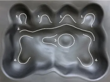
To discuss the considerations in question, we use the mold design shown in Figure4, which features a double-curved form based on isosurface geometry. Its volume has an undulant profile with 12 interconnected, irregular, sphere-like synclastic protrusions, connected by anticlastic regions. In our example, this mold design is iterated twice.
The first important consideration in geometrical error exploration, supporting a successful application of our framework, is the project-specific logic of exploring the errors of the mold. To formulate such a logic in an informed way, we recommend to begin by creating a taxonomy of erroneous mold features, based on the fabrication result of the first mold design. Such an initial, qualitative taxonomy, capturing observable errors that occur, forms a systematic point of departure for the design decisions supporting esthetic explorations.
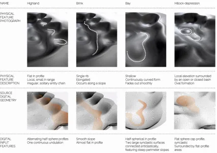
To characterize the spatial nature of these features, we used the landform analogy, expressing our features as highland, brink, hillock, depression, and bay. The features are indicated in Figure5.
Technologies 2019, 7, x 12 of 22
(a) (b)
Figure 4. Initial mold design: (a) Outside view; (b) Inside view.
Figure 5. Types of erroneous features in the first mold: (1) Highland, (2) Brink, (3) Hillock with
surrounding depression, and (4) Bay.
The second important step is to characterize the spatial form of each feature and link it to source digital geometry. This can be done by combining knowledge from the ocular examination of features with knowledge from the video-registered polymer sheet behaviors during forming. In this way, a complete error taxonomy can be constructed, as exemplified in Figure 6. Having this taxonomy at hand makes it possible to select erroneous features for exploration and to systematize the error exploration strategies for each design iteration.
Figure 4.Initial mold design: (a) Outside view; (b) Inside view.
Technologies 2019, 7, x 12 of 22
(a) (b)
Figure 4. Initial mold design: (a) Outside view; (b) Inside view.
Figure 5. Types of erroneous features in the first mold: (1) Highland, (2) Brink, (3) Hillock with
surrounding depression, and (4) Bay.
The second important step is to characterize the spatial form of each feature and link it to source digital geometry. This can be done by combining knowledge from the ocular examination of features with knowledge from the video-registered polymer sheet behaviors during forming. In this way, a complete error taxonomy can be constructed, as exemplified in Figure 6. Having this taxonomy at hand makes it possible to select erroneous features for exploration and to systematize the error exploration strategies for each design iteration.
Figure 5. Types of erroneous features in the first mold: (1) Highland, (2) Brink, (3) Hillock with surrounding depression, and (4) Bay.
The second important step is to characterize the spatial form of each feature and link it to source digital geometry. This can be done by combining knowledge from the ocular examination of features with knowledge from the video-registered polymer sheet behaviors during forming. In this way, a complete error taxonomy can be constructed, as exemplified in Figure6. Having this taxonomy at hand makes it possible to select erroneous features for exploration and to systematize the error exploration strategies for each design iteration.
systematization of operations, conscious choices for modifications in each iteration can be made. Examples of these choices and their geometrical consequences are presented in Figure7.
Technologies 2019, 7, x 13 of 22
Figure 6. Detailed mold error taxonomy.
Such a systematization can begin by defining a collection of error-modifying operations. In our example, they embraced: Addition, i.e., new feature creation; erasure, i.e., existing feature removal; amplification, i.e., existing feature expansion or enlargement; emphasis, i.e., existing feature intensification; and transformation, i.e., conversion of one feature into another. Based on such a systematization of operations, conscious choices for modifications in each iteration can be made. Examples of these choices and their geometrical consequences are presented in Figure 7.
The final consideration, important from the standpoint of artistic design, is the making of a silicone cast from each mold. The production of the casts, as illustrated in Figure 8, is an optional but important aid for the framework implementation, because the digital photographs of the casts can serve as additional guides in the process of erroneous feature bitmap painting.
More generally, the casts shown here are meant to demonstrate the potential of practical application in the production of customized architectural elements from unconventional materials. As shown in Figure 8, the accumulations of translucent pigmented material constituting those casts, caused by the erroneous features generated using our framework, produce unprecedented esthetic effects, indicating opportunities for artistic design innovation.
In terms of optical phenomena, the mold errors yield gradients of color and translucency across the surface of the cast objects. Because these casts were created in layers, using pigments with varying hues, this creates an effect of truly three-dimensional color, applied within one material mass. In terms of spatial perception of architectural form, the regions of excessively accumulated material, caused by the geometrical errors of the mold, underline the curved geometry of the object. In terms of experiencing the physical substance using the sense of touch, they create an unfamiliar sensation of varying pliability and stiffness, promoting a closer than usual examination of the architectural material and of the surface which it constitutes. An additional tactile effect is also generated by the scalloping features demarcating the forming tool traces. These are left intentionally unprocessed within the mold to become transferred into the cast material, resulting in a geometrical pattern of curves, perceptible by eye and hand.
Figure 6.Detailed mold error taxonomy.
The final consideration, important from the standpoint of artistic design, is the making of a silicone cast from each mold. The production of the casts, as illustrated in Figure8, is an optional but important aid for the framework implementation, because the digital photographs of the casts can serve as additional guides in the process of erroneous feature bitmap painting.
More generally, the casts shown here are meant to demonstrate the potential of practical application in the production of customized architectural elements from unconventional materials. As shown in Figure8, the accumulations of translucent pigmented material constituting those casts, caused by the erroneous features generated using our framework, produce unprecedented esthetic effects, indicating opportunities for artistic design innovation.
In terms of optical phenomena, the mold errors yield gradients of color and translucency across the surface of the cast objects. Because these casts were created in layers, using pigments with varying hues, this creates an effect of truly three-dimensional color, applied within one material mass. In terms of spatial perception of architectural form, the regions of excessively accumulated material, caused by the geometrical errors of the mold, underline the curved geometry of the object. In terms of experiencing the physical substance using the sense of touch, they create an unfamiliar sensation of varying pliability and stiffness, promoting a closer than usual examination of the architectural material and of the surface which it constitutes. An additional tactile effect is also generated by the scalloping features demarcating the forming tool traces. These are left intentionally unprocessed within the mold to become transferred into the cast material, resulting in a geometrical pattern of curves, perceptible by eye and hand.
Technologies2019,7, 78 14 of 22 Due to this richness and unconventional character, the abovementioned esthetic effects are yet another important factor to consider when systematizing the logic behind the computational explorations of the geometrical errors in each mold iteration.
Figure 7. The details and results of mold exploration using the framework.
Figure 7.The details and results of mold exploration using the framework.
Technologies 2019, 7, x 15 of 22
Figure 8. Esthetic features of the silicone casts made from the iterated molds.
4.2. The Visual Program Supporting the Mold Error Explorations
To facilitate erroneous feature explorations in a way that dually combines artistic and computational operations, we developed a custom visual program using the Grasshopper® add-on
for 3D modeler Rhinoceros®. The visual program’s modules, shown in Figure 9, support the
abovementioned dual functionality—as discussed below.
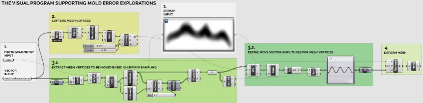
Figure 9. Functional modules of the visual program forming the core of mold error explorations.
The first module of the program gathers the initial inputs for the process: The mesh to be iterated, the bitmap representing the affecting paint strokes, and the curves delineating the boundaries of the paint strokes. In this module, the artistic and imprecise factors are expressed in the nature of the provided inputs; that is, in their levels of precision. For example, the mesh to be iterated forms a precise input if the photogrammetric reconstruction of the mold is used. However, it can also be made imprecise by intentionally subjecting that photogrammetric mesh to smoothing operations in the free-form modeling environment prior to inputting it in the visual program. Another example of an arbitrary factor that can be introduced is the way in which the bitmap of mesh-affecting paint strokes is represented. The paint strokes can, for example, be either expressed with uniform color across each stroke, or represented as gradients of color, e.g., dark in the middle of the stroke and gradually lighter towards the stroke boundary. This choice of paint stroke representation, made arbitrarily by the designer, will affect the computational image sampling in the succeeding modules of the program and the way in which the mesh is deformed.
The second module uses the vector input defining the paint stroke boundaries from the first module to capture the vertices of the mesh that match the locations of the paint strokes. Here, intuitive and imprecise factors can be incorporated by determining how the paint stroke outlines are represented. They can be represented either very precisely, as boundary curves generated based on
Technologies2019,7, 78 15 of 22
4.2. The Visual Program Supporting the Mold Error Explorations
To facilitate erroneous feature explorations in a way that dually combines artistic and computational operations, we developed a custom visual program using the Grasshopper®add-on for 3D modeler Rhinoceros®. The visual program’s modules, shown in Figure9, support the abovementioned dual functionality—as discussed below.
Figure 8. Esthetic features of the silicone casts made from the iterated molds.
4.2. The Visual Program Supporting the Mold Error Explorations
To facilitate erroneous feature explorations in a way that dually combines artistic and computational operations, we developed a custom visual program using the Grasshopper® add-on
for 3D modeler Rhinoceros®. The visual program’s modules, shown in Figure 9, support the
abovementioned dual functionality—as discussed below.
Figure 9. Functional modules of the visual program forming the core of mold error explorations.
The first module of the program gathers the initial inputs for the process: The mesh to be iterated, the bitmap representing the affecting paint strokes, and the curves delineating the boundaries of the paint strokes. In this module, the artistic and imprecise factors are expressed in the nature of the provided inputs; that is, in their levels of precision. For example, the mesh to be iterated forms a precise input if the photogrammetric reconstruction of the mold is used. However, it can also be made imprecise by intentionally subjecting that photogrammetric mesh to smoothing operations in the free-form modeling environment prior to inputting it in the visual program. Another example of an arbitrary factor that can be introduced is the way in which the bitmap of mesh-affecting paint strokes is represented. The paint strokes can, for example, be either expressed with uniform color across each stroke, or represented as gradients of color, e.g., dark in the middle of the stroke and gradually lighter towards the stroke boundary. This choice of paint stroke representation, made arbitrarily by the designer, will affect the computational image sampling in the succeeding modules of the program and the way in which the mesh is deformed.
The second module uses the vector input defining the paint stroke boundaries from the first module to capture the vertices of the mesh that match the locations of the paint strokes. Here, intuitive and imprecise factors can be incorporated by determining how the paint stroke outlines are represented. They can be represented either very precisely, as boundary curves generated based on
Figure 9.Functional modules of the visual program forming the core of mold error explorations.
The first module of the program gathers the initial inputs for the process: The mesh to be iterated, the bitmap representing the affecting paint strokes, and the curves delineating the boundaries of the paint strokes. In this module, the artistic and imprecise factors are expressed in the nature of the provided inputs; that is, in their levels of precision. For example, the mesh to be iterated forms a precise input if the photogrammetric reconstruction of the mold is used. However, it can also be made imprecise by intentionally subjecting that photogrammetric mesh to smoothing operations in the free-form modeling environment prior to inputting it in the visual program. Another example of an arbitrary factor that can be introduced is the way in which the bitmap of mesh-affecting paint strokes is represented. The paint strokes can, for example, be either expressed with uniform color across each stroke, or represented as gradients of color, e.g., dark in the middle of the stroke and gradually lighter towards the stroke boundary. This choice of paint stroke representation, made arbitrarily by the designer, will affect the computational image sampling in the succeeding modules of the program and the way in which the mesh is deformed.
The second module uses the vector input defining the paint stroke boundaries from the first module to capture the vertices of the mesh that match the locations of the paint strokes. Here, intuitive and imprecise factors can be incorporated by determining how the paint stroke outlines are represented. They can be represented either very precisely, as boundary curves generated based on the paint stroke color gradient data, or imprecisely, as boundary curves that only approximately capture the bitmap paint stroke outlines. This choice will affect the precision with which the mesh vertices are captured for further operations.
The third module executes a two-stage process. Firstly, it defines the movement values for the mesh vertices, based on the sampling of color brightness of chosen pixels from the paint stroke bitmap. Then, optionally, it can employ a function graph to remap and distort the values from the bitmap sampling. Here, more arbitrary and intuitive factors can be introduced directly within the computational functions of the module. For the first stage of the process, this can be done by setting the paint stroke bitmap sampling parameters in various ways, from precise mapping at high-resolution to imprecise mapping at low-resolution. For the second stage, the image sampling values can be either precise, i.e., left as they are without remapping, or be altered through resampling using various function graphs for a more imprecise effect.
4.3. The Visual Program for Robot Toolpath Generation
The visual program for robot toolpath creation relies on the parametric modeling functions of the Grasshopper®visual programming interface for Rhinoceros®, and on the functions of the Kuka|prc add-in for Grasshopper® that enable the generation of G-code executable on our particular robot. The program approximates mold geometry into a polyline toolpath. The toolpath has the form of a unidirectional, constant level profile.
The first module of the program takes the mold geometry represented as a NURBS patch as its input. It then generates NURBS section curves for the patch, spaced at a specified distance to define the forming increment.
In the next module, the global bounding box for the curves is constructed, accompanied by the extraction of XYZ coordinates of its corner points. One of the uppermost points is selected to mark the starting location for the forming process. In the next module, this point is used to find points on the section curves that lie closest to it. These points delineate the locations of retractions of the forming tool that accompany the progression from one path loop to another.
A step that follows is the approximation of the separate NURBS contours into one polyline. This is done by rebuilding the NURBS contours into curves with degree 1 and with the number of control points reduced to half of the number of control points of each initial NURBS section curve. Additional linear curves demarcating the horizontal and vertical tool traveling movements are also constructed between the points of tool retraction defined in the earlier module. These are joined with the polylines approximating the sections to form one polyline.
In the final step, the number of control points for that polyline is reduced with a numerically given tolerance to enable shorter process duration and faster processing by the robot controller. Lastly, a file containing robot instructions is generated in a proprietary programming language KRL to control our robot.
5. Discussion
5.1. Research Results in a Broader Context
Today, the scarce number of research publications on architectural SPIF indicates that knowledge of this promising fabrication method is still limited and should be expanded further. Therefore, considering SPIF research in a broader context of the engineering disciplines can provide, to a certain extent, a background for discussing the significance of our study and its role in the development of the current approaches to handling the errors in fabrication.
5.2. Advantages of the Approach
In contrast to the engineering approaches described above, the framework resulting from this study embodies an alternative, bottom-up approach to erroneous feature handling. Although the framework is supported by digital and computational means, which by definition are precise, an advantage is that it also offers several entry points for ambiguous explorations that may be preferred by some designers, especially those with an artistic orientation. The framework’s construction and implementation workflow also ensure that geometric feature explorations take place in a gradual, iterative manner. The benefit of this is that each iteration opens up several potential avenues for further explorations, all originating from one initial design.
Importantly, we also believe that an advantage of our method is its capacity to be combined with conventional, precision-oriented fabrication. This is important for a wider application of our process in non-standard building element manufacturing. Practical applications at the scale of an actual building will necessitate that some parts of the formed molds, such as edges that connect with other building elements, maintain high levels of geometrical precision, while the middle zones of the geometry can be treated in a less strict and more explorative manner. Further research is needed to find out how to make such a combined approach effective from an industrial application standpoint.
Another advantage of our method pertains to a novel mode of operation that it offers, in which the material is allowed to shape and compose itself partially on its own, with the human designer and the fabrication machine only to a certain extent guiding the process instead of controlling it entirely. The conventional mode of material crafting and processing, in which the material is merely formed, transformed, and reshaped, either by the designer’s hand or by the machine tool, is therefore expanded in our framework. This can be considered beneficial from an esthetic standpoint, as the material accumulations caused by the intentionally tweaked mold errors emphasize the intricate esthetic attributes of the material cast into the mold, offering an opportunity for unusual, bottom-up design feature generation.
Our framework therefore mediates a novel approach to design, in which designers can work very closely with material behaviors and react to these behaviors in an artistic, intuitive, and ambiguous way. Influencing these behaviors in an indirect manner creates a possibility to shape the expressive attributes of the design through the medium of the material, instead of mere drawing. This seems unique in light of the conventional design methods that often operate in a top-down manner. We hope that our research can play a part in the emergence of an alternative strand of architectural design methods, featuring material agency as an enriching design medium, existing side-by-side with the conventional design means.
5.3. Challenges, Limitations, and Future Research Directions
One of the major challenges experienced during our study was the difficulty to predict the material behaviors during forming, and therefore, to know which geometry iterations are producible. We tackled this challenge in two ways. Firstly, we developed a practice of carefully registering each forming process on camera and of carefully analyzing the video material. This enabled us to relate each failure to the global and local geometry features and to the material behaviors accompanying the particular moment of failure. Through this, we could develop a deeper understanding of qualitative factors influencing the failures. The second undertaken measure was to synthesize knowledge from previous studies on SPIF failures and adapt this knowledge to the specific context of our molding process, which seemed to have slightly improved our success rate in the successive process runs.
difficult to foresee balance between the geometry, the locations and actions of the forming tool, and the internal stresses in the material needs to hold.
In our exemplary implementation, we had one unsuccessful iteration run. However, for a designer new to the process, the number of failures could have been higher, as experience and deep general knowledge of material-specific behaviors are important determinants of success. Consequently, to facilitate the use of our approach, further research is needed that constructs a comprehensive and accessible knowledge base about architectural SPIF, relevant from the design exploration standpoint, thoroughly discussing the typical material behaviors and formulating general recommendations for exploring the process in an effective way.
Given that research on SPIF has a long tradition, but accurate methods of error prediction for large-scale free-form geometries have not yet been fully developed, evokes the question of whether the noted imprecision could get modeled and induced in a fully digital way, saving materials. Answering such a question extends beyond the scope of this architectural research work. It can only be addressed by interdisciplinary engineering research. Nonetheless, a wish directed at future research in engineering would be for accessible, easily understandable and fast computational simulations of the polymer SPIF process, directed at architects and designers, allowing for evaluations of specific geometries for failure or success in early-stage design.
Another potential drawback of the framework, related to its application in the explorative design process, is the need to switch between the software environments of the 3D modeler and the bitmap editing program during the explorations. It would be perhaps more convenient to stay within the environment of the 3D modeler and its visual programming add-on, and carry out all intuitive and artistic explorations only therein. To facilitate this, direct coupling of intuitive drawing with mesh alterations could be done, by means of real-time painting of mold features directly onto the mesh, supported with the visual interface of the 3D modeler, giving instant feedback of the esthetic results in 3D view. The first step in such further development of the tooling part of our framework would be to incorporate an already existing physics simulation engine, Kangaroo—an add-on for Grasshopper®. This add-on contains some functions allowing for more direct manipulation of meshes and real-time simulation of dynamic mesh deformation processes. However, further studies are needed to develop an efficient way of incorporating such a tool and its specific functionalities into our framework.
5.4. Potential Artistic Error Exploration Avenues Stemming from the Current Work
Future work expanding our error exploration approach could include methods from industrial inspection that evaluate the production errors not only digitally, but also in the physical space of the model. In this respect, future work could be inspired by research on tolerance analysis that uses sensing strategies to directly incorporate manufacturing process data to react to the manufacturing errors [50]. In our case, new work triggered by this concept could embrace the development of a sensing system that registers and follows the spatial deformations of the material as it is being processed, compares this data with the original digital model, and uses the difference values to alter the robot toolpath either in real-time or in the next design iterations. Such an approach could provide a conceptually interesting and a highly interactive way of exploring the erroneous material behaviors in architectural SPIF of polymers.
6. Conclusions
The perception of fabrication errors in a positive light presents a new disciplinary challenge for digital design and fabrication in architecture. That is, because it positions the conventionally precision-and control-oriented architectural computing within an unknown setting of material uncertainty. The discipline needs to respond to this positioning in ways never practiced before. Completely new agendas for handling the conditions of material unpredictability and uncertainty need to be formulated to enable this new opportunity for innovation to be seized and consolidated into a fully-fledged new design paradigm.
Currently, even though partly embraced, acknowledged imprecision and deliberate error are still exceptional in the field of computational architectural design. However, the exciting challenges they introduce to architectural computing imply great potential for enriching the mainstream practice. The value of welcoming error and imprecision lies in its capacity to move beyond the esthetic canon of the perfect artefact of architectural production towards a novel esthetic of material agency whose beauty lies in the artefact imperfections arising from the processes of making, informed by designers, digital machines, and material behaviors. The tools and workflows of the framework presented herein therefore provide the first instances of enabling media through which such enactment of material agency might occur. Through our research, we hope to spark further interest and development of this novel line of inquiry in architectural computing and fabrication.
Funding:This research was funded by the Swedish Research Council Vetenskapsrådet, grant number 2015-01519.
Acknowledgments:The author acknowledges the work of Karin Hedlund, who assisted in setting up the digital and robotic fabrication processes in this study. The author would also like to acknowledge the peer reviewers of this article for their insightful feedback on the work.
Conflicts of Interest:The author declares no conflicts of interest. The funders had no role in the design of the study; in the collection, analyses, or interpretation of data; in the writing of the manuscript; or in the decision to publish the results.
References
1. Castle, H.; Sheil, B.High Definition: Zero Tolerance in Design and Production; Wiley: London, UK, 2014. 2. Menges, A. The New Cyber-Physical Making in Architecture: Computational Construction. Arch. Des.
2015,85, 28–33. [CrossRef]
3. Eigensatz, M.; Kilian, M.; Schiftner, A.; Mitra, N.J.; Pottmann, H.; Pauly, M. Paneling Architectural Freeform Surfaces.ACM Trans. Graph.2010,29, 45. [CrossRef]
4. Li, Y.; Liu, Y.; Wang, W. Planar Hexagonal Meshing for Architecture. IEEE Trans. Vis. Comput. Graph.
2014,21, 95–106. [CrossRef] [PubMed]
5. Pottmann, H. Architectural Geometry and Fabrication-Aware Design. Nexus Netw. J.2013,15, 195–208. [CrossRef]
6. Calleja, A.; Bo, P.; Gonzalez, H.; Barto ˇn, M.; López de Lacalle, L.N. Highly Accurate 5-Axis Flank CNC Machining with Conical Tools.Int. J. Adv. Manuf. Technol.2018,97, 1605–1615. [CrossRef]
7. Fallböhmer, P.; Rodríguez, C.A.; Özel, T.; Altan, T. High-Speed Machining of Cast Iron and Alloy Steels for Die and Mold Manufacturing.J. Mater. Process. Technol.2000,98, 104–115. [CrossRef]
8. Castaneda, E.; Lauret, B.; Lirola, J.M.; Ovando, G. Free-form Architectural Envelopes: Digital Processes Opportunities of Industrial Production at a Reasonable Price.J. Facade Des. Eng.2015,3, 1–13. [CrossRef] 9. Dittrich, M.A.; Gutowski, T.G.; Cao, J.; Roth, J.T.; Xia, Z.C.; Kiridena, V.; Ren, F.; Henning, H. Exergy Analysis
of Incremental Sheet Forming.Prod. Eng.2012,6, 169–177. [CrossRef]
10. Franzen, V.; Kwiatkowski, L.; Neves, J.; Martins, P.A.F.; Tekkaya, A.E. On the Capability of Single Point Incremental Forming for Manufacturing Polymer Sheet Parts. In Proceedings of the 9th International Conference on Theory of Plasticity (ICTP2008), Gyeongju, Korea, 7–11 September 2008.
12. Anzalone, P.; Del Signore, M.; Wit, A.J. Notes on Imprecision and Infidelity. In Proceedings of the 38th Annual Conference of the Association for Computer Aided Design in Architecture (ACADIA 2018), Mexico City, Mexico, 18–20 October 2018; pp. 16–17.
13. Kobayashi, P.; Slocum, B. Introduction: Recalibration. In Proceedings of the 38th Annual Conference of the Association for Computer Aided Design in Architecture (ACADIA 2018), Mexico City, Mexico, 18–20 October 2018; pp. 12–15.
14. Atwood, W.A. Monolithic Representations. In Matter: Material Processes in Architectural Production; Borden, G.P., Meredith, M., Eds.; Routledge: London, UK, 2012; pp. 199–205.
15. Gürsoy, B. From Control to Uncertainty in 3D Printing with Clay. In Proceedings of the 36th eCAADe Conference, Lodz, Poland, 19–21 September 2018; Volume 2, pp. 21–30.
16. Mohite, A.; Kochneva, M.; Kotnik, T. Material Agency in CAM of Undesignable Textural Effects: The Study of Correlation between Material Properties and Textural Formation Engendered by Experimentation with G-Code of 3D Printer. In Proceedings of the 36th eCAADe Conference, Lodz, Poland, 19–21 September 2018; Volume 2, pp. 293–300.
17. Goldman, M.; Myers, C. Freezing the Field: Robotic Extrusion Techniques Using Magnetic Fields. In Proceedings of the 37th Annual Conference of the Association for Computer Aided Design in Architecture (ACADIA 2017), Cambridge, MA, USA, 2–4 November 2017; pp. 260–265.
18. Dickey, R. Soft Computing in Design: Developing Automation Strategies from Material Indeterminacies. In Proceedings of the 17th International Conference CAAD Futures 2017, Istanbul, Turkey, 12–14 July 2017; pp. 419–430.
19. Belanger, Z.; McGee, W.; Newell, C. Slumped Glass: Auxetics and Acoustics. In Proceedings of the 38th Annual Conference of the Association for Computer Aided Design in Architecture (ACADIA 2018), Mexico City, Mexico, 18–20 October 2018; pp. 244–249.
20. Swackhamer, M.; Satterfield, B. Breaking the Mold: Variable Vacuum Forming. In Proceedings of the 33rd Annual Conference of the Association for Computer Aided Design in Architecture (ACADIA 2013), Cambridge, ON, Canada, 21–27 October 2013; pp. 269–278.
21. Tessmann, O.; Rumpf, M.; Eisenbach, P.; Grohmann, M.; Äikäs, T. Negotiate My Force Flow: Designing with Dynamic Concrete Formwork. In Proceedings of the 34th eCAADe Conference, Oulu, Finland, 22–26 August 2016; Volume 1, pp. 93–102.
22. Kalo, A.; Newsum, M.J.; McGee, W. Performing: Exploring Incremental Sheet Metal Forming Methods for Generating Low-Cost, Highly Customized Components. InFabricate 2014: Negotiating Design and Making; Gramazio, F., Kohler, M., Langenberg, S., Eds.; UCL Press: London, UK, 2017; pp. 166–173.
23. Nicholas, P.; Stasiuk, D.; Nørgaard, E.; Hutchinson, C.; Thomsen, M.R. An Integrated Modelling and Toolpathing Approach for a Frameless Stressed Skin Structure, Fabricated Using Robotic Incremental Sheet Forming. InRobotic Fabrication in Architecture, Art and Design 2016; Reinhardt, D., Saunders, R., Burry, J., Eds.; Springer: Cham, Switzerland, 2016; pp. 62–77.
24. Kalo, A.; Newsum, M.J. An Investigation of Robotic Incremental Sheet Metal Forming as a Method for Prototyping Parametric Architectural Skins. InRobotic Fabrication in Architecture, Art and Design 2014; McGee, W., Ponce de Leon, M., Eds.; Springer: Cham, Switzerland, 2014; pp. 33–49.
25. Kalo, A.; Newsum, M.J. Bug-out Fabrication: A Parallel Investigation of the Namib Darkling Beetle and Incremental Sheet Metal Forming. In Proceedings of the 34th Annual Conference of the Association for Computer Aided Design in Architecture (ACADIA2014), Los Angeles, CA, USA, 23–25 October 2014; pp. 531–538.
26. Lublasser, E.; Braumann, J.; Goldbach, D.; Brell-Cokcan, S. Robotic Forming: Rapidly Generating 3D Forms and Structures through Incremental Forming. In Proceedings of the 21st International Conference of the Association for Computer-Aided Architectural Design Research in Asia (CAADRIA), Melbourne, Australia, 30 March–2 April 2016; pp. 539–548.
27. Pedgley, O.; ¸Sener, B.; Lilley, D.; Bridgens, B. Embracing Material Surface Imperfections in Product Design. Int. J. Des.2018,12, 21–33.