Version 5 for Mac
®
and Windows
®
User Guide
Molecular Devices Corporation
Molecular Devices Corporation SoftMax Pro Software
Version 5 for Mac® and Windows® User Guide Copyright
© Copyright 2007, Molecular Devices Corporation. All rights reserved. No part of this publication may be reproduced, transmitted, transcribed, stored in a retrieval system, or translated into any language or computer language, in any form or by any means, electronic, mechanical, magnetic, optical, chemical, manual, or otherwise, without the prior written permission of Molecular Devices Corporation, 1311 Orleans Drive, Sunnyvale, California, 94089, United States of America.
Trademarks
SoftMax, FlexStation, FLIPR, SoftMax, SpectraMax, Analyst, and VMax are registered trademarks and Automix, EMax, PathCheck, SpectraPlate, SpectraStrip, ThermoMax, UVMax, VersaMax, ScreenStation, ScreenPlay, and Acquest are trademarks of Molecular Devices Corporation. These trademarks are not to be used in any type of promotion or advertising without written permission from Molecular Devices Corporation.
All other trademarks are the property of their respective owners.
SoftMax Pro and use thereof is covered by issued (U.S. patent nos. 5,766,875 5,959,738 6,188,476 6,232,608 6,236,456 6,320,662 6,339,472 6,404,501 and foreign patents) and pending U.S. and foreign patents.
SpectraMax M2 and use thereof is covered by issued (U.S. patent nos. 5,112,134 5,766,875 5,959,738 6,188,476 6,232,608 6,236,456 6,313,471 6,316,774 6,320,662 6,339,472 6,404,501 6,496,260 and foreign patents) and pending U.S. and foreign patents.
Automix is covered by U.S. Patent Number 5,112,134; PathCheck is covered by U.S. Patent Number 5,959,738.
WASTE text engine (c) 1993-1998 Marco Piovanelli.
Disclaimer
Molecular Devices Corporation reserves the right to change its products and services at any time to incorporate technological developments. This manual is subject to change without notice. Although this manual has been prepared with every precaution to ensure accuracy, Molecular Devices Corporation assumes no liability for any errors or omissions, nor for any damages resulting from the application or use of this information.
Questions? Phone: +1-800-635-5577
+1-408-747-1700 Fax: +1-408-747-3603 Web: www.moleculardevices.com
1. Introduction
Major Functions of SoftMax Pro . . . 1
Instrument Control . . . 1
Data Collection and Display . . . 2
Data Reduction and Plotting . . . 2
Immediate Results Reporting and Analysis. . . 2
Two Available Editions: Standard and GxP . . . 2
2. Installation & Setup
Installation . . . 3
Installing an Instrument. . . 3
Computer System Requirements . . . 3
Installing SoftMax Pro . . . 3
Uninstalling SoftMax Pro . . . 3
Running the Software for the First Time . . . 4
Communicating with an Instrument . . . 4
Launching SoftMax Pro Software. . . 4
Entering Registration Information . . . 4
Connecting the Instrument via USB . . . 4
Single Port Adapters. . . 5
Multiple-Port Adapters . . . 5
Troubleshooting Instrument Connections . . . 6
LMax II . . . 6
Instrument Preferences. . . 6
Setting Preferences. . . 7
Reader Settings . . . 7
Manual Export Format . . . 8
Save Data After Read (AutoSave) . . . 9
Print Document After Read . . . 11
The Protocols Menu . . . 11
3. SoftMax Pro Interface
The SoftMax Pro Application Window . . . 13
WYSIWYG Display . . . 13
Temperature Display . . . 14
Read. . . 14
Reference Button . . . 14
StakMax Button. . . 14
Incubator Button . . . 15
Automix Button. . . 15
Drawer Button. . . 15
Instrument Settings and Control . . . 15
Instrument Settings . . . 15
Read. . . 15
Close Drawer, Open Drawer . . . 16
Incubator . . . 16
Ref . . . 16
Experiments . . . 16
Selecting an Experiment. . . 16
Manipulating Experiments. . . 17
Sections . . . 17
Active Section Menus. . . 17
Manipulating Sections . . . 17
Notes Section. . . 19
Plate Section . . . 20
Group Section . . . 22
CuvetteSet Section . . . 23
Graph Section . . . 24
Creating a Default Protocol. . . 25
4. Data Collection
Introduction to Data Collection . . . 27
Instrument Settings . . . 27
Instrument Operation . . . 27
Instrument Settings Vary for Different Models . . . 28
Read Type . . . 28
Read Mode . . . 30
Wavelengths. . . 31
Shake (LMax II and LMax II384 Only) . . . 32
Integration (SpectraMax L, LMax II and LMax II384 Only) . . . 32
Injection and Delay (SpectraMax L and LMax II384 Only). . . 32
Injection Wells (SpectraMax L and LMax II384 Only) . . . 33
Sensitivity (Gemini; SpectraMax L, M2, M2
e, M5, M5
e; FlexStation;
Fluorescence/Luminescence Only) . . . 33
M2, M2
e, M5, M5
e) . . . 34
Automix. . . 39
Blanking (Pre-Read Plate) . . . 40
AutoCalibrate. . . 40
Well Scan Editor . . . 41
Assay Plate Type . . . 42
Strips/Wells to Read. . . 43
Compound Source (Flex Only) . . . 43
Compound Transfer (Flex Only) . . . 43
Triturate (Flex Only) . . . 44
Pipette Tips Layout (Flex Only). . . 45
Compound & Tip Columns (Flex Only) . . . 45
Settling Time (SpectraMax M5 and M5
eOnly). . . 47
Speed Read (Absorbance Only; Endpoint, Kinetic and Spectrum Scan Only) . . . 47
Column Wavelength Priority . . . 47
AutoRead. . . 48
Template Editor . . . 48
Selecting Wells or Cuvettes in the Template Editor . . . 48
Group . . . 49
Sample . . . 51
Assign . . . 51
Clear . . . 51
Series . . . 51
Blanking . . . 53
Copying and Pasting Templates. . . 55
Exporting and Importing Templates . . . 56
Reading a Microplate or Cuvette . . . 56
Data Collection from a Microplate . . . 56
Data Collection from a Cuvette . . . 57
Calibration. . . 59
Data Display During a Reading . . . 59
5. Data Analysis
Introduction . . . 61
Data Display . . . 61
The Display Dialog Box. . . 61
Data Reduction . . . 65
Endpoint Reads . . . 66
Kinetic Reads . . . 66
Spectrum Reads . . . 69
Well Scan. . . 70
Flex Reads . . . 71
Data Mode (%Transmittance/Absorbance) . . . 72
Custom Reduction Formulas . . . 72
Recalculation Options . . . 74
Group and Graph Sections . . . 74
Group Sections . . . 74
Graph Section . . . 77
6. Tutorials
Tutorial 1: Quantitative Endpoint Protocol Tutorial . . . 88
Step 1: Create a New Data File . . . 88
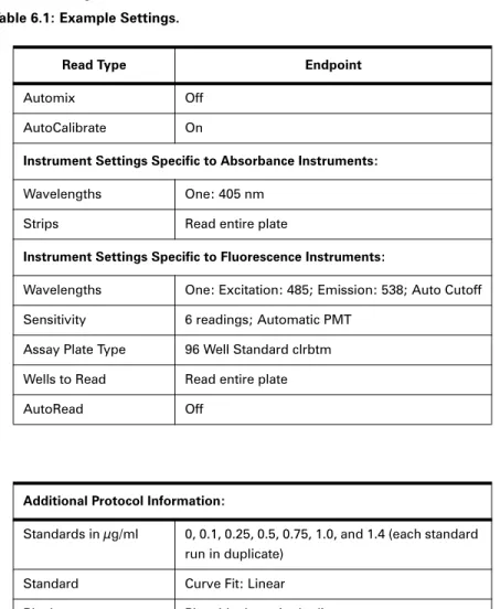
Step 2: Define Instrument Settings . . . 89
Step 3: Define Template . . . 90
Step 4: Set Reduction Parameters. . . 92
Step 5: Set Display Parameters . . . 92
Step 6: Save the Protocol . . . 92
Step 7: Read the Plate . . . 93
Step 8: Data Analysis—Group Sections . . . 93
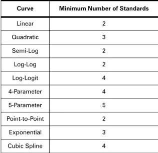
Step 9: Data Analysis—Standard Curve . . . 96
Tutorial 2: EC 50 Protocol Tutorial (Flex only) . . . 96
Step 1: Create a New Data File . . . 97
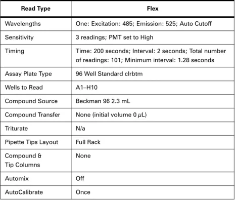
Step 2: Define Instrument Settings . . . 97
Step 3: Define Template . . . 98
Step 4: Set Reduction Parameters. . . 98
Step 5: Set Display Parameters . . . 99
Step 6: Save the Protocol . . . 99
Step 7: Read the Plate . . . 99
Step 8: Data Analysis—Group Sections . . . 100
Step 11: Print a Report . . . 103
7. File Management & Printing
File Creation and Management . . . 105
Data Files. . . 105
Protocol Files . . . 105
Saving Files Manually . . . 106
AutoSave . . . 106
Printing . . . 107
Printing Reports. . . 107
Including or Excluding Sections. . . 107
Changing Section Order . . . 107
Changing Text Format. . . 107
Import/Export. . . 107
Export . . . 107
Import . . . 110
Importing and Exporting Templates . . . 111
Exporting Graphs. . . 113
Copying and Pasting . . . 113
File Protection . . . 113
Setting a Password . . . 114
Changing a Password . . . 114
Removing a Password. . . 114
Suspending a Password . . . 114
8. SoftMax Pro GxP
Solution Overview. . . 115
How the Programs Work Together . . . 116
GxP Admin Features . . . 116
Using SoftMax Pro GxP . . . 117
User Log On . . . 117
Files . . . 117
GxP Menu . . . 118
Statements . . . 118
Locking and Unlocking Sections . . . 119
9. Robotics & LIMS Integration
Introduction . . . 121
Sample Source Code and Applications. . . 121
Remote Control . . . 121
Send/Receive Remote Commands . . . 121
Summarizing Remote Commanding . . . 124
Programmer Notes. . . 125
Remote Control in SoftMax Pro GxP . . . 126
SoftMax Pro Commands . . . 126
Visual Basic (Excel Macro) Example . . . 132
MFC C++ Interface to SoftMax Pro Remote Commands that Return Values . . . 134
MFC Example Code . . . 134
A. Appendix
Glossary of Terms . . . 137
SoftMax® Pro software controls Molecular Devices’ spectrophotometers, Absorbance, Luminescence, and Fluorescence microplate readers—providing extensive data calculation and analysis capabilities under a GLP/GMP work environment for pharmaceutical, bio-technology, academic, hospital, and government customers.
Over 120 assay protocols are included to speed life science research and drug discovery assay development and screening. Researchers can customize Experiment protocols, ana-lyze and display data, and create meaningful reports. The straightforward yet powerful programming capabilities of SoftMax Pro can further enhance any specialized data collec-tion and analysis needs through custom assay development.
This industry-leading software package is also widely integrated with industry-leading robotics systems. Optional Validation Tools are also available to reduce the time, effort and cost of certifying and re-validating MDC laboratory tools.
Two editions are available: SoftMax Pro software and SoftMax Pro GxP. Both support all MDC instruments including: SpectraMax®, VersaMax®, VMax®, EMax®, Gemini, ThermoMax®, and FlexStation®. Data from Analyst®, and FLIPR® systems can also be easily imported and analyzed.
SoftMax Pro GxP is a special software release that includes full user and permission con-trol and audit trail generation in addition to all the data collection and analysis features found in the Standard edition. With the audit trail features in SoftMax Pro GxP, all Experiments are fully traceable and can be completely reconstructed.
SoftMax Pro 5.2 is available for PC-compatible computers using Windows 2000 and XP, and Mac computers using OSX 10.2.8 or greater.
1.1.
MAJOR FUNCTIONS OF SOFTMAX PRO
1.1.1. INSTRUMENT CONTROL
SoftMax Pro allows you to set up and run a complete protocol for all instruments. Instru-ment settings can be saved as a protocol file and used repeatedly for reading different microplates or cuvettes. All stand-alone instrument functions can be controlled using the software. In addition, SoftMax Pro provides capabilities that are not available when using an instrument in stand-alone mode such as user-defined Kinetic run times, read intervals, Automix parameters, etc.
1.1.2. DATA COLLECTION AND DISPLAY
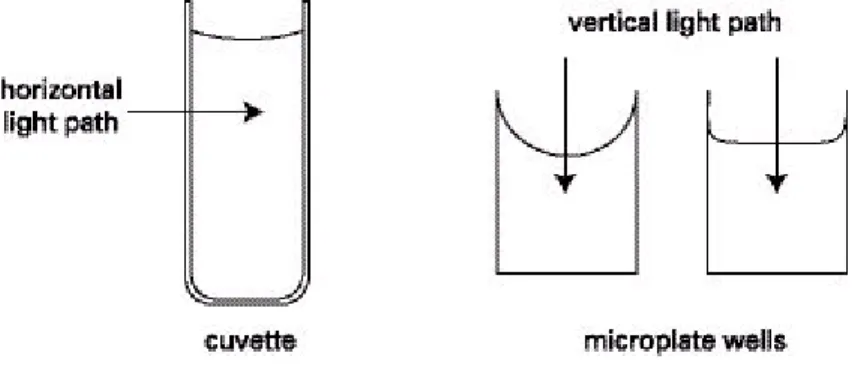
SoftMax Pro collects and stores all raw data received from the instrument. Data is dis-played in a grid format that corresponds to the wells in a microplate (all instruments) or individual cuvettes (using SpectraMax Plus, Plus384, M2, M2e, M5e or M5).
SoftMax Pro can collect data from one or more microplates or cuvettes and store it in a single data file, using the same or different instrument settings for different microplates or cuvettes. For example, microplates containing different samples can be read using the same or different modes, all within the same Experiment.
In addition to displaying data collected from a Molecular Devices microplate system instrument, you can import, display, and analyze data collected from either a FLIPR® or Analyst instrument.
1.1.3. DATA REDUCTION AND PLOTTING
You can manipulate or reduce the raw data using dozens of built-in formulas or define your own analysis structure to quickly and easily summarize the raw data. More than one reduction can be shown, and results from different microplates and cuvettes can be com-pared within the same Experiment.
1.1.4. IMMEDIATE RESULTS REPORTING AND ANALYSIS
Once you have defined instrument settings, and have customized a SoftMax Pro software data file with assay information, reduction settings, custom columns in Group sections, and summary objects, you can “Save As…” a Protocol file type to create an assay template that can then be used and distributed throughout a department or company for highly repeatable data collection and analysis that is completed the second the plate read has completed.
1.2.
TWO AVAILABLE EDITIONS: STANDARD AND GXP
Two editions of SoftMax Pro are available: Standard and GxP.
SoftMax Pro software provides instrument control and analysis functions for all Spectra-Max, FlexStation, Gemini, and earlier instruments as well as import and analysis of data files from FLIPR and Analyst instruments.
SoftMax Pro GxP, together with a Molecular Devices plate reader and Molecular Devices GxP Admin software, provides a fully integrated hardware and software solution for adherence to Good Manufacturing Practices (GMP), Good Laboratory Practices (GLP), and many other regulatory compliance requirements including 21 CFR Part 11.
2.1.
INSTALLATION
2.1.1. INSTALLING AN INSTRUMENT
Please consult your instrument manual for instructions on connecting your instrument to a computer.
2.1.2. COMPUTER SYSTEM REQUIREMENTS
Recommended computer hardware and operating system software specifications that will ensure proper operation of SoftMax Pro can be found online at:
http://www.moleculardevices.com/downloads/SMPv5x_SysReqs.pdf.
Molecular Devices recommends that you increase the amount of RAM in your computer to a minimum of 2 GB in the following cases:
>If you plan to use SoftMax Pro with a FlexStation instrument.
>If you plan on using your microplate reader with the StakMax™ integrated plate han-dling system.
>If you use large (more than 40 Plate sections per file) or complicated (384 well ADME protocols, etc.) files.
>If you plan to use robotic applications. 2.1.3. INSTALLING SOFTMAX PRO
Follow these instructions to install SoftMax Pro: 1 Insert the SoftMax Pro CD into the CD-ROM drive.
2 Windows: Open My Computer and then double-click the CD-ROM drive icon to display its contents.
Mac: Double-click the CD icon to display its contents.
3 Double-click the SoftMax Pro v5.2 Installericon and follow the screen prompts. 2.1.4. UNINSTALLING SOFTMAX PRO
Before uninstalling the program, make sure to backup your data and any saved files to a folder outside of the SoftMax Pro folder, because uninstalling deletes the entire SoftMax
Windows: To uninstall SoftMax Pro software, click the Windows Start menu, then Set-tings, then Control Panel. Double-click Add or Remove Programs, then scroll down to find
SoftMax Pro v5.2. Click this once to select it, then click the Remove button. This is the recommended method of removing SoftMax Pro software from a Windows-based com-puter since it also removes related information from the Windows Registry.
Mac: To remove SoftMax Pro, drag the SoftMax Pro folder to the Trash, then empty the Trash.
2.2.
RUNNING THE SOFTWARE FOR THE FIRST TIME
2.2.1. COMMUNICATING WITH AN INSTRUMENT
To ensure that SoftMax Pro can communicate with your instrument, turn on the instru-ment prior to starting SoftMax Pro.
If using a USB-to-serial adapter, please be sure to obtain the latest software driver from the manufacturer before connecting to your instrument.
2.2.2. LAUNCHING SOFTMAX PRO SOFTWARE
After the instrument is powered on and has completed its start-up sequence, double-click the SoftMax Pro icon on your desktop to start the program.
2.2.3. ENTERING REGISTRATION INFORMATION
The first time you run SoftMax Pro after installation, a first-launch wizard will guide you through the setup process. In particular, it requires you to enter your name, company, and the serial numbers of SoftMax Pro and the connected instrument.
The software serial number can be found in the SoftMax Pro software box, and the instru-ment serial number is located on a label affixed to the back of the instruinstru-ment.
You will also be prompted to register your software with Molecular Devices over an inter-net connection. Registration of SoftMax Pro activates the product warranty and entitles you to receive software updates when available.
2.3.
CONNECTING THE INSTRUMENT VIA USB
Many Windows and Mac-based computers no longer have a standard RS232 serial port. If you have a computer without a standard serial port, you will need to use a USB-to-serial adapter.
These adapters are available at many computer supply stores as well as through online merchants. Molecular Devices recommends serial adapters made by Keyspan (www.key-span.com), as they have been proven repeatedly in field operations.
Please refer to the instrument manuals for additional instructions related to the USB-only instruments from Molecular Devices: the SpectraMax L Luminometer and StakMax plate handling system.
2.3.1. SINGLE PORT ADAPTERS
Single port adapters are very straightforward:
1 Connect the MDC serial cable to the USB-to-serial adapter.
2 Connect the USB-to-serial adapter to an open USB port on your computer. 3 Turn your MDC microplate instrument on by pressing the black toggle to the [|]
position.
4 Launch SoftMax Pro software and select the Edit > Preferences menu item.
5 Select the appropriate serial port (most often COM1) from the Serial Port pull-down menu.
6 You should now see a three-dimensional image of your instrument in the top-left corner of SoftMax Pro software immediately beneath the File menu.
7 Confirm that your instrument is communicating properly by clicking on the instrument image. Your specific reader should be automatically selected in the Reader
pull-down menu.
2.3.2. MULTIPLE-PORT ADAPTERS
Before attempting to use a multi-port adapter, be sure you have downloaded and installed the very latest software driver from the manufacturer’s website. If you are using a two-port adapter from Keyspan such as their USA-28x Twin Serial Adapter, you MUST be sure to connect your MDC microplate reader to PORT 1. Ports are usually identified on the side or top of the adapter itself. With the 28-x, a small “1” is embossed in the plastic of the adapter.
1 Connect the MDC serial cable to PORT 1 on your USB-to-serial adapter. 2 Connect the USB-to-serial adapter to a open USB port on your computer. 3 Turn your MDC microplate instrument on.
4 Launch SoftMax Pro software.
5 Select Edit > Preferences menu item, and make sure the correct serial port is selected.
Note: If you are using a multiple-port adapter with more than one MDC microplate reader, be sure to use the serial cables that shipped with your MDC microplate instrument. Non-MDC serial cables will NOT work with Non-MDC microplate instruments.
Note: These USB-to-serial adapters do NOT work without installing the correct software driver. If you are not sure you have or are using the latest driver available, please check with the manufacturer directly. Drivers can normally be downloaded from the manufacturer’s
website. Be sure you have installed the latest software drivers before using a USB-to-Serial adapter with your MDC microplate instrument.
2.4.
TROUBLESHOOTING INSTRUMENT CONNECTIONS
If the instrument is properly connected and turned on, you will see the instrument’s icon in the upper-left corner of the SoftMax Pro window below the menus, and the correct instrument is selected in the Edit > Preferences dialog box.
If the instrument is not properly connected or is turned off, the instrument icon in the upper left-hand corner of the window will appear with a question mark. Check that the connection is secure and that the instrument is powered on.
2.4.1. LMAX II
The LMax II and LMax II384 instruments require manual selection of the instrument in the Preference dialog in order to establish communication. This is due to the different baud rate requirement for LMax II instruments.
2.4.2. INSTRUMENT PREFERENCES
If you have problems communicating with a connected instrument, open the Edit > Pref-erences dialog box and select the appropriate communications port (ports that are not available are disabled):
>Windows: use COM1 through COM9.
>Mac: use a USB-to-serial adapter with an available USB port.
>If you do not have an instrument connected to the computer but want to use SoftMax Pro, select None.
>Click OK to close the Preferences dialog and the instrument icon should appear without a question mark.
If the serial port setting is correct and the instrument is on, yet communication is still fail-ing, quit SoftMax Pro, turn off power to both the computer and the instrument, and check that the cable connections between the instrument and computer are secure. Turn both machines on again and restart SoftMax Pro.
2.5.
SETTING PREFERENCES
Before using SoftMax Pro we recommend checking the global application settings in the
Edit > Preferences dialog box. Here you will find:
>Reader settings, such as the port used for the connection to the instrument, supported readers, and filter settings for use with Series I microplate readers.
>Automatic file saving and printing options.
>File export settings when data is exported using the File > Import > Export menu item. 2.5.1. READER SETTINGS
Reader
When a reader is connected and is powered on, the Reader list automatically reports the instrument connected to the computer.
If a reader is not connected to the computer, the Reader list displays the model of the last reader connected.
A protocol file can be written if an instrument is neither connected to the computer nor selected in the preferences. Choosing an instrument can be useful, however, since the options available in the Plate > Settings dialog box depend on the choice of instrument here. For example, with a SpectraMax you can configure up to six wavelengths, whereas you cannot do this with a VMax.
Filters
Filter settings apply only to EMax, VMax, UVMax, and ThermoMax instruments. Check that the filter wavelength displayed for each position matches the wavelength of the filter physically installed in each position of the filter wheel. If the settings in this dia-log box are not correct, subsequent readings will generate incorrect data, because SoftMax Pro has no way to verify the identity of the filters in the filter wheel.
The SpectraMax 250 accepts two optional filters, but the wavelengths for these filters are entered using the instrument's front panel. For specific information regarding how to install optional filters in the SpectraMax 250, refer to the instrument manual. Serial Port
Check that the setting for the serial port matches the physical port used to connect the computer and the instrument.
If you are using a Keyspan serial adapter with a Mac computer, set the port to Printer. None
Select None to use the serial ports on your computer for other purposes, such as a modem connection, a network connection, or printing.
When None is selected, the Status Bar in SoftMax Pro shows an instrument icon with a ? through it, along with the words No port selected. You cannot communicate with your instrument.
Port Speed
When a FlexStation instrument is selected as the reader, a Port Speed option is available. SoftMax Pro automatically detects the baud rate of the instrument to which the computer is connected and establishes a communication rate accordingly. This option allows you to view the baud rate that is being used and to manually set a different rate. This should not be done unless a serial communications problem occurs.
2.5.2. MANUAL EXPORT FORMAT
Data collected by SoftMax Pro can be exported for use with other software or for archiving.
Time / Plate / XML
For Plate sections, you can choose one of the following three formats: >Time exports data in single column text for each well.
>Plate exports data in a text matrix corresponding to a microplate grid. >XML exports data in an XML file format.
CuvetteSet sections are automatically exported in the time format. Include Labels
Includes microplate column labels for all exported data.
This is most useful for Group section data, since the column headings in the Group table are shown, including any other calculated data in Summaries, etc.
Labels included with Plate and CuvetteSet sections show “1-12” headers for 96-well Plate section data exported in Plate format; 384-well plate data have “1-24” headers; CuvetteSet section labels show “A1,” “A2,” etc., representing the cuvettes shown in the CuvetteSet sec-tion.
Include Filename and Date
Includes the file name and date in the file with the exported data. Include Account Info
Includes the name of the user who generated the file. This option is available only if you are using SoftMax Pro GxP.
Interpolate Wells (FlexStation Only)
Interpolation is used to normalize the Kinetic read times of wells against the read time of the first well in each column. Because injection occurs at the same time in all wells of a
column but the wells are read sequentially, the reaction advances in the other wells while the first is being read. Consequently, the data in the other wells must be interpolated against the amount of time that has elapsed between injection and reading in order to compare data from one well to another, and to compare data from one run to another. Once exported, well-interpolated data cannot be re-imported into SoftMax Pro.
This interpolation is different to the interpolation option in the Plate > Reduction dialog box.
384 to 4 × 96 time format
This is used when you are using 384 well plates and conducting extended Kinetic reads with more than 255 time points. This option enables you to work around architectural issues in Microsoft Excel that prevent the import of data files with more than 255 col-umns.
2.5.3. SAVE DATA AFTER READ (AUTOSAVE)
When this option is enabled, the collected data is saved automatically to a user-defined location immediately after each plate read is completed. This greatly reduces the likeli-hood of lost data, particularly when AutoSave is set to save files to corporate network vol-umes that are backed up on a regular basis.
You can add as many AutoSave instances as desired, each with its own settings. After click-ing Add, you are presented with the Add AutoSave Entry dialog that allows you to specify the location, file naming conventions, and file format. Once specified, simply click OK to save these settings.
From the Preferences dialog, click Edit after selecting an AutoSave instance to modify the
AutoSave settings. Location
You can control where files are AutoSaved by modifying the options listed in the Location
section. The default location set in SoftMax Pro is an invalid dummy path that should be deleted before saving another location. To save data files to an assigned folder, click
Assigned Folder and choose a different folder.
If the AutoSave function reports an error or if files are saved in the wrong location, it may be that a previous version of SoftMax Pro was not uninstalled prior to installing a newer version.
Name
You can control the automatic naming of all AutoSaved files by modifying the options listed in the Name section.
Protocol’s Name
Assigned Name
If selected, any text in this field is automatically inserted at the beginning of each AutoSaved file name. Files are also numbered sequentially, for example “Data 1”, “Data 2”, etc.
If the Assigned Name field is left blank, the date and time of each plate read is used as the file name for each AutoSaved file. For example, the first file AutoSaved on November 18th, 2005 at 9:01am and 58 seconds would be AutoSaved as “11-18-05-090158”.
Append UserID (GxP ONLY)
Checking Append UserID adds the UserID for the user logged on to SoftMax Pro GxP to the Assigned Name or Protocol Name specified.
Append Date
Checking Append Date adds the date to the Assigned Name or Protocol Name speci-fied.
If Append Time is not also checked, SoftMax Pro indexes the runs for that day start-ing with “1” and increments with each successive run. For example, the first file AutoSaved on November 18th, 2005 at 9:01am and 58 seconds would be named as “Data-11-18-05 1”, while the second file AutoSaved would be named
“Data-11-18-05 2”, and so on. Append Time
Checking Append Time adds the time in the format “hhmmss” to the Assigned Name or Protocol Name specified. For example, the first file AutoSaved on November 18th, 2005 at 9:01am and 58 seconds would be named as “Data-090158 1”, while the sec-ond file AutoSaved would be named at the exact time the secsec-ond read completed, “Data-090744 1”, and so on.
Format
Format options allow you to specify what type of file is AutoSaved. Version 5 supports three file formats: SoftMax Pro, XML, and Tab-Delimited.
After each Plate section or CuvetteSet section is read, the data is saved to a new file. For protocols with more than one Plate section, each subsequent AutoSave file contains all the data from the just-completed plate read, as well as all previous readings. For example, if you open a protocol containing two Plate sections and a CuvetteSet section and read all three with AutoSave enabled:
>File1 contains data for PlateSection1.
>File2 contains data for PlateSection1 AND PlateSection2.
>File3 contains data for both Plate sections AND the CuvetteSet section. This functionality applies to both SoftMax Pro and text file formats.
SoftMax Pro File
When selected, your data will be AutoSaved as a proprietary SoftMax Pro file format: .pda (standard) or .eda (GxP) file format. If your protocol contains more than one Experiment section, only the Experiment containing the plate/cuvette being read is AutoSaved.
XML File
XML is supported for data export and AutoSave. XML is the optimal file format if you plan on importing all read data into other data collection and storage applica-tions—specifically, LIMS (Laboratory Information Management System) or SDMS (Scientific Data Management System) packages.
Tab-Delimited File
When selected, your data will be AutoSaved as a .txt file format, which can be opened by any word processor, spreadsheet, or database program. If you are saving data to a text file, use Append to File to save all data for all Plate and CuvetteSet sections to a single .txt file, or use Create New File to save the data from each plate to a new file. 2.5.4. PRINT DOCUMENT AFTER READ
Checking this box enables automatic printing of a report after each plate is read. The report contains information from each section that is designated to be included in the report. For more information on reports, and including or excluding sections, see Section 7.2., “Printing”.
2.6.
THE PROTOCOLS MENU
The Protocols menu is a dynamically generated menu, listing all top-level folders and the protocol files they contain. When SoftMax Pro software is installed, several folders—each containing predefined protocol files for use with SoftMax Pro software—are automatically created within the Program Files / Molecular Devices / SoftMax Pro folder.
To change the folder used to generate the Protocols menu, choose Protocols > Set Folder and navigate to the desired folder. This allows you to display a custom set of protocols that your company may be using instead of the set that ships with SoftMax Pro software. Additionally, custom folders can be created within Program Files / Molecular Devices / Soft-Max Pro. Once a protocol file (.ppr or .epr file) is placed in this custom folder, both the folder name and the protocol name are listed in the Protocols menu.
Some protocols will not be appropriate for your particular instrument (they might have reductions that are appropriate only for Absorbance or Fluorescence instruments, for example), so please check the Revision Notes section located at the top of each MDC-authored protocol file for reader suitability before using.
This can be useful in the following circumstances:
>If you want to create protocol files on a computer that is running SoftMax Pro but is not connected to an instrument.
>If you want to create protocols for an instrument other than the one connected to the computer.
This chapter describes some of the main elements of the SoftMax Pro interface, and their logical relationships to each other.
For detailed instructions on setting up an experiment, and acquiring and analyzing data, see Chapters 4 through 6.
3.1.
THE SOFTMAX PRO APPLICATION WINDOW
The SoftMax Pro application window consists of two elements: >A Menu Bar and Status Bar at the top of the application window.
>An untitled document showing an Experiment data file divided into a number of sec-tions. The displayed sections depend upon the configuration of the default protocol, and the type of instrument chosen in Edit > Preferences or connected to the computer.
3.2.
WYSIWYG DISPLAY
SoftMax Pro has been designed to provide you with a WYSIWYG (What You See Is What You Get) preview of printed reports. Consequently, the width of a document is con-strained by the width set for the printed page size.
You can change the dimensions and orientation of the printed page and consequently the display size in the File > Print Setup (Windows) or File > Page Setup (Mac) dialog boxes.
3.3.
STATUS BAR
Below the menus at the top of the SoftMax Pro window is a Status Bar that displays instrument controls. The Status Bar can be shown and hidden using View > Show Status
and View > Hide Status respectively.
Depending on the type of instrument that is connected to the computer or selected in the
Edit > Preferences dialog, some or all of the following items are in the Status Bar: 3.3.1. INSTRUMENT ICON
Indicates that the instrument is communicating properly with the computer. If an “?” appears on top of the icon, the computer is not making proper contact with the instru-ment.
3.3.2. TEMPERATURE DISPLAY
Reports the current temperature within the microplate chamber in degrees Celsius. With the SpectraMax M2, M2e, M5, M5e, Plus, and Plus384, the SoftMax Pro Status Bar shows the temperature within the microplate chamber. This may be different from the front panel of the instrument, which displays the temperature within the cuvette chamber. The readings should be very similar to one another after both chambers have reached equilibrium. During warm-up, however, you may notice a discrepancy in temperatures, which is normal.
3.3.3. READ
If a Plate or CuvetteSet section is active or if only a single Plate or CuvetteSet section has been created in the Experiment section, clicking the Read button starts the reading. This reading is based on the settings chosen in the Control > Instrument Settings dialog box. If more than one Plate or CuvetteSet section has been created in the Experiment section and no Plate or CuvetteSet section is currently active, clicking the Read button opens a dialog box asking you to select the plate or cuvette to read.
If AutoRead is selected in the Instrument Settings, all of the plates/cuvettes will be read sequentially.
3.3.4. REFERENCE BUTTON
This feature is active only when a CuvetteSet is selected. Use the Reference button to mea-sure a reagent blank. The Reference value is stored and subtracted automatically from the Read values. The reference reading may be taken before or after the sample reading. This setting applies only to the SpectraMax M2, M2e, M5, M5e, Plus, and Plus384. 3.3.5. STAKMAX BUTTON
Displays the StakMax software interface, allowing you to control the StakMax microplate handling system. The StakMax software interface accessed through SoftMax Pro is the only method of interacting with the StakMax instrument.
When the StakMax software is launched it automatically connects to the StakMax instru-ment, and the current status of the instrument is displayed in the Status line in the Stak-Max software.
StakMax is compatible with SpectraMax L, M2, M2e, M5, M5e, Gemini EM and XPS, and the new models of the following instruments (compatible models are identifiable by their serial numbers): SpectraMax Plus384 MNR-xxxxx), 340PC384 (Serial#-LNR-xxxxx), 190 (Serial#-NNR-xxxxx), VersaMax (Serial#-BNR-xxxxx).
Click the Help button in the StakMax software user interface to open the StakMax User Guide, which provides complete documentation on the use of StakMax.
3.3.6. INCUBATOR BUTTON
Displays the Control > Incubator dialog box, allowing you to set and regulate the tempera-ture of the microplate/cuvette chamber. The temperatempera-ture setting can be left at the default or can be specified by entering a different value.
The incubator setting is independent of the protocol being run. Running an assay does not automatically set the temperature set point. After a reading, however, the temperature set point, range, and average temperature are recorded in the saved file.
3.3.7. AUTOMIX BUTTON
Shakes the microplate. This is a manual shaking of the plate as opposed to an automatic shaking that can be chosen in the instrument settings and is not available for the EMax. 3.3.8. DRAWER BUTTON
Opens or closes the microplate drawer.
3.4.
INSTRUMENT SETTINGS AND CONTROL
In addition to the buttons on the Status Bar, most commands for instrument control are in the Control menu.
3.4.1. INSTRUMENT SETTINGS
Use Plate > Settings to configure all parameters for a plate read, such as the read type (End-point, Kinetic, Fast Kinetic, Spectrum, Well Scan, or Flex), read mode (Absorbance, Fluo-rescence, Luminescence, Fluorescence Polarization, Time Resolved Fluorescence), wavelength settings, Automix parameters, pre-read blanking, strips, PathCheck, Auto-Read, timing for Kinetic runs, Speed Read for Spectrum scans, and plate type. Each Plate or CuvetteSet section can have a different instrument setup.
The available options in Plate > Settings depend on the type of instrument that is con-nected to the computer, or selected in Edit > Preferences (see Section 2.5., “Setting Prefer-ences”).
Plate > Settings is only available when a Plate section is selected in the data file. 3.4.2. READ
In a single plate experiment, Control > Read reads the plate or cuvette immediately. If no Plate section or CuvetteSet section is active, the Read command displays a dialog box in which you select the Plate section or CuvetteSet section to read.
The default Plate section or CuvetteSet section, selected by pressing the Return key, is chosen on these criteria:
>The next unread Plate or CuvetteSet section. >The first plate or cuvette, if all have been read. Menus are disabled while reading is in process. 3.4.3. CLOSE DRAWER, OPEN DRAWER
Use these commands to close and open the instrument drawer so that a plate can be inserted or removed.
3.4.4. INCUBATOR
Control > Incubator allows you to turn the incubator on or off. When on, you can enter a setting to regulate the temperature in the microplate chamber.
This command is available for all instruments except Emax, VMax, UVMax and LMax II. 3.4.5. REF
Control > Ref causes the SpectraMax M2, M2e, M5, M5e, Plus, or Plus384 to read the cuvette in the cuvette port and applies the reading as a reference to all cuvettes in the active CuvetteSet section.
This command is available only when a CuvetteSet section is active and a SpectraMax M2, M2e, M5, M5e, Plus, or Plus384 is connected or chosen in Edit > Preferences.
3.5.
EXPERIMENTS
SoftMax Pro collects data from one or more microplates or cuvettes and stores it in a sin-gle data file, using the same or different instrument settings for different microplates or cuvettes. For example, microplates containing different samples can be read using the same or different modes, all within the same Experiment.
Each SoftMax Pro file contains at least one Experiment. Within an Experiment are one or more sections.
Experiments provide quick access to different types of information without the need to open or refer to multiple files.
3.5.1. SELECTING AN EXPERIMENT
An Experiment can be selected by clicking the Experiment title bar (the area that shows the Experiment number) with the mouse cursor. Selecting an Experiment changes its tool bar from light gray to dark gray, and allows you to manipulate the whole Experiment, such as deleting or duplicating it, or adding new sections.
Multiple Experiments can be selected by holding down the Shift key while clicking the individual title bars of the Experiments.
3.5.2. MANIPULATING EXPERIMENTS New Experiment
You can create a new Experiment by selecting the Experiment > New Experiment com-mand.
If an existing Experiment is active when this command is chosen, all of the information from the previous Experiment except for the data is copied to the new Experiment. Rename Experiment
When an Experiment is created it is given a placeholder name, like “Experiment#1”. You can rename an Experiment by double-clicking on its title bar to open an edit dialog. Duplicate Experiment
You can make a copy of a selected Experiment (excluding data) in the same file by select-ing the Edit > Duplicate[Experiment Name] command.
You can duplicate multiple Experiments by Shift-selecting them and then selecting the
Edit > Duplicate Selection command. Delete Experiment
You can delete a selected Experiment by selecting the Edit > Delete [Experiment Name]
command.
You can delete multiple Experiments by Shift-selecting them and then selecting the Edit > Delete Selection command.
Reorder Experiments
You can change the order that Experiments appear in a file by drag and drop. Select the title bar of the Experiment and drag it to its new position in the file, marked by a thick black line.
3.6.
SECTIONS
A section is a part of the SoftMax Pro Experiment window intended to perform a specific set of functions. There are five types of sections—Notes, Plate, CuvetteSet, Group, and Graph—and each type of section has a specific icon that identifies it.
3.6.1. ACTIVE SECTION MENUS
When a section is active, a section-specific menu is added to the SoftMax Pro main appli-cation menus between the View menu and the Protocols menu: Notes, Plate, Cuvette,
Group, or Graph.
3.6.2. MANIPULATING SECTIONS
When active, the section title bar is colored dark gray. Multiple sections can be made active at the same time by Shift-selecting them.
New Section
You can create a new section (except Group sections) by selecting the appropriate New
command from the Experiment menu: New Notes, New Plate, New CuvetteSet, New Graph. If an existing section is active when this command is chosen, all of the information in the section except data is copied to the new section.
Group sections are created automatically when you define new groups in the Template Editor, and can also be created with the Duplicate command.
Section Name
When a section is created it is given a name based on its section type, like “Notes#1”. You can rename a section by double-clicking on its title bar to open the Section Name dia-log, or select Section Name from the Section (Notes, Plate, Cuvette, Graph) menu.
Duplicate Section
You can make a copy of a selected section (excluding data) in the same file by selecting the
Edit > Duplicate [Section Name] command.
You can duplicate multiple sections by Shift-selecting them and then selecting the Edit > Duplicate Selection command.
Duplicating a CuvetteSet section creates a copy of the previous CuvetteSet section, including the last reference that was read.
Delete Section
You can delete a selected section with the Edit > Delete [Section Name] command. You can delete multiple sections by Shift-selecting them and then selecting the Edit > Delete Selection command.
Deleting a Group section automatically deletes references to that group from the Tem-plate.
View Section
Each Experiment in a file has its name added to the View menu as a command, and all its sections are available in cascading sub-menu commands. Selecting a section from one of these sub-menus opens the section in the current window.
Expand and Collapse Sections
Newly created Experiments and sections are initially shown expanded. To simplify naviga-tion within an Experiment data file, you can collapse secnaviga-tions to show just their tool bars.
To expand or collapse a single section, click its triangular indicator located in the top left corner of the tool bar.
To expand or collapse all sections in an Experiment, or multiple Experiments in a file, use the View > Expand and View > Minimize commands, or their associated hot keys Ctrl+[ and Ctrl+].
Reorder Sections
You can change the order that sections appear in an Experiment by drag and drop. Select the title bar of the section and drag it to its new position in the Experiment, marked by a thick black line.
Open Section in New Window
To open an active section and edit it in a separate window, select New Window from the active section menu (Plate, Cuvette, Graph, Notes, or Group).
Closing the new section window or expanding the section in the original window saves changes made to the section.
Print Section
The File > Print [Section Name] commands enables you to print just the active sections. 3.6.3. NOTES SECTION
Notes sections are used to record text or to report Summary data pertaining to the Exper-iment. You can enter text in this section by typing directly, or by creating Summaries con-taining formulas for displaying reduced data.
A Summary is part of a Notes section that is generated from formulas applied to data in the Experiment.
Text in Notes sections can be formatted (font face, font size, and font style) using the Edit > Text Style dialog box.
You can create multiple Notes sections within the same Experiment. New Summary
Notes > New Summary opens a dialog box allowing you to: >Name a new Summary.
>Enter a formula to be used for the Summary. Edit Summary
Use Notes > Edit Summary to edit the name and formula of an existing Summary. See the SoftMax Pro Formula Reference Guide for a complete guide to formulas.
3.6.4. PLATE SECTION
Plate sections are used to collect data from the instrument, and to define data display and data reduction. If you read the same physical plate twice with different instrument set-tings, you would have two Plate sections.
The Template Editor in the Plate section is used to create a map of the contents of the microplate.
Plate sections are divided into: >Tool bar.
>Data display (shown in a microplate grid format).
>Instrument settings, shown to the right of or below the data display, depending on the plate type and printer settings.
>Reduction settings, shown to the right of or below the data display, depending on the plate type and printer settings.
>Fluid transfer and checksum status for the FlexStation instrument.
If the plate grid in the Plate section is colored, then a template has been defined for the Plate section. Each group defined in the template has a different color (the icon of the cor-responding group table has the same color).
If your experiment requires multiple plates, you can create as many Plate sections as needed.
Template
The Template button (or Plate > Template) opens the Template Editor, which allows you to describe the samples in the wells, providing the link between the raw data and analysis groups. You can create new groups in the template or assign wells to already established groups.
A group is a set of associated samples that has been created in the Template. Some group types (such as Standard or Unknown) can be created as part of the default protocol, and you can create others as required. When you create a group and assign samples to it, a cor-responding group table is automatically created.
Each Plate section in your Experiment requires a template to be created to identify groups within that plate. However, two or more Plate sections may use the same template, or the same groups may be used in different templates.
Reduction
The Reduction button (or Plate > Reduction) opens the Reduction dialog box, which is used to specify the reduction of the data collected from the microplate reader, typically to a sin-gle number per well.
Options available in the Reduction dialog box depend on the type of reading performed (Endpoint, Kinetic, Spectrum, Well Scan, or Flex) and the instrument used to collect the data.
See Chapter 5, “Data Analysis” for more details on Data Reduction. Graph
The Graph button (or Plate > Graph) creates a graph from the data in the selected wells in the active Plate section. It is enabled both during data collection and after data has been acquired for a Kinetic, Spectrum, Well Scan, or Flex reading.
Double-clicking a well also creates a graph of the data in that well.
Graph is disabled if the instrument settings are for an Endpoint reading. Mask
The Mask button (or Plate > Mask) allows you to remove selected wells from the data analysis.
Mask is a toggle, so that selecting masked wells and choosing the Mask command unmasks them.
Copy and Paste Data
Data can be copied from one Plate section to another or from one CuvetteSet section to another within SoftMax Pro:
1 Make the source section active by clicking on it. 2 Select Edit > Copy (a C; Ctrl+C).
3 Create a new section, if necessary, or make the destination section active. 4 Select Edit > Paste (a V; Ctrl+V).
When copying Plate sections, all wells are copied, even if only a subset of wells is selected. It is not possible to copy and paste the data from selected wells only.
It is possible, however, to copy individual cuvettes or groups of cuvettes and paste these into other CuvetteSet sections. If you are copying cuvette data and the target CuvetteSet section does not contain the appropriate cuvettes for the data that is to be pasted, new cuvettes are created automatically. Note that pasting cuvette data for only some cuvettes clears the existing data from all other cuvettes in that section.
If the Instrument Settings of the target section do not match the settings from the section being copied, the Instrument Settings for the target section are updated to match. Copy and Paste Template
There are two ways to copy and paste a template, depending on whether or not you want to keep the same group names.
Keep Group Names
Plate > Copy Template copies the template from the active Plate section to the Clip-board, so that it can be pasted into a different Plate section using Plate > Paste Tem-plate, either in the same or in a different Experiment, or into a Plate section in another SoftMax Pro file.
Pasting a template into an Experiment where the groups from the source template do not exist creates the groups. Existing groups of the same name are not changed by the pasting process.
For example, if the source Experiment contains the groups “Standards” and
“Unknown,” and the destination Experiment already contains the group “Standards”, the group “Unknown” is created but the group “Standards” in the destination Exper-iment is unchanged.
If you copy and paste the template within the same Experiment, no new groups are created. Group names can be edited in the pasted template, but these changes are made in the original template also.
New Group Names
The second way to copy and paste a template allows you to keep the same sample lay-out and sample names and concentrations, but also allows you to change the Group names independent of the source template:
1 Open the Template Editor and select all wells. 2 Select a C or Ctrl+C to copy the layout.
3 Open the Template Editor for a new Plate section and select all wells. 4 Select a V or Ctrl+V to paste the layout.
Export Template
Use Plate > Export Template to export a template to a tab-delimited text or XML file. The file format must be specified first in the global Preferences dialog.
Import Template
Use Plate > Import Template to import a template from a tab-delimited text or XML file. 3.6.5. GROUP SECTION
A Group section is a table that shows all of the information for a particular sample group that has been defined in a Plate template.
Unlike other section types, Group sections are created automatically when you create or select groups for an Experiment in the Template Editor.
Group sections are divided into: >Tool bar.
>The body of the Group table. >Summaries.
Group Settings
Use the Group > Group Settings dialog box to edit the Group name, descriptors, units and format.
The Column Format field in the Group Settings dialog specifies the default columns for the data calculated and reported in the active group.
Delete Group
You can delete a selected group with the Edit > Delete [Group Name] command. Deleting a Group section automatically deletes references to that group from the Tem-plate.
Duplicate Group
You can duplicate a selected group with the Edit > Duplicate [Group Name] command. Group section tables can also be duplicated. When a Group table is duplicated, its name is added to the Template Editor’s list of group names (but the group is not assigned to any wells).
3.6.6. CUVETTESET SECTION
CuvetteSet sections are used to collect data from the cuvette port of the SpectraMax M2, M2e, M5, M5e, Plus or Plus384, to define an analysis template, and to define data display and data reduction. The Template Editor in the CuvetteSet section is used to describe the contents of the Cuvette.
CuvetteSet sections are divided into: >Tool bar.
>Data display (can be shown in three different ways: three samples per row, one sample per row, and in a grid of cells similar to a microplate format).
>Instrument settings, shown to the right of the data display. >Reduction settings, shown at the bottom of the data display.
When colors appear in the name labels above individual cuvettes (when displayed as one or three cuvettes per row) or when colored areas appear when the CuvetteSet section is displayed as a grid, this means a template has been defined for the CuvetteSet section. Each group defined in the template has a different color (the icon of the corresponding
If your experiment requires multiple cuvettes, you can add up to 96 cuvettes in a single CuvetteSet section or create more than one CuvetteSet section.
The commands described in the Plate section above also apply to CuvetteSet sections. 3.6.7. GRAPH SECTION
Graph sections are used to plot information from groups as scatter plots or bar graphs. Once a graph has been created, new plots can be added and deleted, the axes can be cus-tomized, and the size of the graph can be changed. Grid lines can be enabled or disabled (default is enabled).
Graph sections are divided into: >Tool bar.
>The body of the Graph section. >Plot information below the graph.
You can create more than one Graph section within an Experiment data file, and plots in the Graph section can be created from any Experiment in the file.
Graph Options
Use the Graph Options button (or Graph > Graph Options) to configure the style and con-tent of a graph.
You can select from three types of graphs:
>Scatter (with symbols plotted and the points connected). >Cluster Bar.
>Stack Bar.
Select New to add a new plot to the graph from any of the Group sections in the Experi-ment.
X-Axis
Use the X-Axis button (or Graph > X-Axis) to edit X-axis parameters (tick marks, scale, label, gridlines, and auto-range).
Y-Axis
Use the Y-Axis button (or Graph > Y-Axis) to edit Y-axis parameters (tick marks, scale, label, gridlines, and auto-range).
Export Graph Exports a graph to file.
On the Mac, the graph is saved in PICT format; on Windows, it is saved in EMF (Enhanced Metafile) format.
3.7.
CREATING A DEFAULT PROTOCOL
While earlier versions of SoftMax Pro software opened to a specific Tutorial template, SoftMax Pro versions 4.8 and later open to a blank protocol that matches the instrument connected to the computer.
If no instrument is connected to the computer and if no default protocol file exists, Soft-Max Pro uses the instrument chosen in Edit > Preferences to create a new protocol. To use a customized protocol file as your default template every time SoftMax Pro is launched, you must specifically save a file as your default protocol:
1 Create a new file using the File > New menu command. 2 Modify all preferences and settings as necessary. 3 Add any desired text information in Notes sections.
4 Customize the columns, formulas, and reductions to suit your research needs.
5 When the file is to your liking, select the Protocols > Save As Default Protocol menu item to save this as your new default protocol that will be displayed every time SoftMax Pro software is launched.
It is not mandatory to create a default protocol because the software detects the ment connected to the computer and automatically creates a new file based on instru-ment. For example, if connected to a Fluorescence instrument with a cuvette port, the software displays fluorescence units on both a Plate section and a CuvetteSet section; if connected to an Absorbance instrument with no cuvette port, the software displays absor-bance units on a Plate section only. In addition to these sections, a blank Notes section is created.
Finally, you can change your default protocol at any time. To remove the default protocol used, simply delete the file “Default Protocol” from Program Files / Molecular Devices / SoftMax Pro v5.2.
4.1.
INTRODUCTION TO DATA COLLECTION
A typical process for preparing, collecting, and analyzing data is as follows: 1 Launch SoftMax Pro software.
2 Create Plate and CuvetteSet sections as needed. 3 Specify instrument settings using Plate > Settings.
4 Define templates, reduction parameters, and display parameters.
5 Prepare the microplates or cuvettes to be read and place them in the instrument. 6 Start the reading.
7 Save the data file.
8 If required, modify templates, reduction parameters, or display parameters. 9 Analyze the data using Group section tables and Graph sections.
10Save the final data file.
4.2.
INSTRUMENT SETTINGS
Instrument settings are associated with a Plate or CuvetteSet section in a SoftMax Pro Experiment. You can create more than one Plate or CuvetteSet section in a single Experi-ment, and the instrument settings associated with each Plate section can be different. You must specify instrument settings (wavelengths, read mode, etc.) prior to reading a microplate or cuvette.
When you have defined instrument settings, a summary is displayed to the right of the data display in the Plate or CuvetteSet section.
4.2.1. INSTRUMENT OPERATION
Instrument settings are made in the Plate > Settings dialog box. You must select a Plate sec-tion to make this menu available.
The operation of individual instruments is only described here to illustrate the functional-ity of the software. For complete information about the function of the instrument or how to set it up for a reading, consult the instrument manual.
4.2.2. INSTRUMENT SETTINGS VARY FOR DIFFERENT MODELS
Only the settings relevant to the instrument connected to the computer or chosen in
Edit > Preferences are available in the Plate > Settings dialog box. However, this guide lists many of the common settings across instrument models.
4.2.3. READ TYPE
The Read type specifies the spatial, temporal and chromatic properties of the read. Endpoint
In an Endpoint read, a reading of each microplate well is taken at a single or at multiple wavelengths.
Depending on the read type selected, values can be reported as optical density, %Trans-mittance (if this is selected in the Reduction dialog box), relative fluorescence units (RFU), or relative luminescence units (RLU).
For multiple reads per well, see Section 5.3.2., “Kinetic Reads” and Section 4.2.16., “Well Scan Editor”.
LMax II and LMax II384 and SpectraMax L Only
Endpoint on an LMax II or SpectraMax L instrument line means: > A single integration of samples in 96- or 384-well plates.
> Two injections, if desired, in selected wells of a 96-or 384-well plate (only one injection is possible in 384-well plates with the LMax II instrument line). A pre-read of the microplate can be made before injection of buffer or reagent, or reading of the samples. Normal pre-read uses the same integration time as sample read, while Special pre-read allows you to enter a different integration time.
Values are reported as relative luminescence units (RLU); the default reduced value is !Lm1.
Kinetic
In a Kinetic read the data are collected over time with multiple readings taken at reg-ular intervals. To achieve the shortest possible interval for Kinetic readings, choose wavelengths in ascending order.
The default reduced values calculated for Kinetic data are VMax (units/sec or units/ min), Time to VMax (seconds), Onset Time (seconds), Time at Minimum, Time at Maximum, Time at 1/2 Maximum, Slope, and Area Under Curve.
Spectrum
Depending on the read mode selected, a Spectrum read measures optical density, %Transmittance (if this has been selected in the Reduction dialog box), relative
fluo-rescence units (RFU), or relative luminescence units (RLU) across a spectrum of wavelengths.
All Spectrum readings are made using the scanning monochromator of the instru-ment.
Well Scan
A Well Scan read takes one or more readings of a single well of a microplate at single or multiple wavelengths. Every option available for Endpoint reads is available for Well Scans.
Values reported are optical density, %Transmittance, relative fluorescence units (RFU), or relative luminescence units (RLU).
Flex
Flex is used to set up reads on FlexStation instruments, where one has to configure compound additions as well as the usual plate reading parameters.
Dual Read (SpectraMax L and LMax II384 only)
Also an Endpoint reading, Dual Read is designed to perform two separate integra-tions, one after each of two possible injections in any or all wells of a 96-well plate or 384-well plate (LMax II384 can inject twice in 96-well plates only). Integration times for both readings are the same, unless otherwise specified.
You can program a delay after each injection, and you can read all or only some of the wells in the plate. Pre-reading a microplate is not possible with this read type. Default values reported are relative luminescence units (RLU). The default reduced value is !Lm1.
Fast Kinetic (SpectraMax L, LMax II and LMax II384 Only)
Fast Kinetic performs repeated readings of one or more wells of a 96- or 384-well microplate up to a 100-point maximum integration. All readings of a single well are made before the next well is read. Pre-reading a microplate is not possible in Fast Kinetic reads.
One or two injections can be made in each well of a 96-well microplate (and 384-well plate for the SpectraMax L) at the start of the reading. Integration time can be set from 0.1 to 100 seconds.
4.2.4. READ MODE
The Read mode is the form of detection used by the instrument. All read types except Well Scan are available for all read modes. Not all read modes are supported by all instruments.
Fluorescence (RFUs)
Fluorescence is light emitted by a substance resulting from the absorption of incident radiation. The governing equation for fluorescence is:
Fluorescence = (extinction coefficient) × (concentration) × (quantum yield) × (excitation intensity) × (pathlength) × (emission collection efficiency)
Absorbance(ODs)
Absorbance is the amount of light absorbed by a solution. In the absence of turbidity:
Absorbance = optical density – reflection Luminescence (RLUs)
Luminescence is the emission of light by processes that derive energy from essentially non-thermal changes, the motion of subatomic particles, or the excitation of an atomic system by radiation.
With the SpectraMax L, M5 and M5e, selecting the Luminescence read mode displays the integration time box next to the Read Type selection.
Time Resolved Fluorescence (RFUs)
Most fluorescent substances are not suitable for this type of reading. However, the fluores-cence emitted by lanthanide dyes is delayed long enough to measure fluoresfluores-cence after the lamp is turned off. Time resolved fluorescence is used to reduce the amount of back-ground noise that interferes with fluorescence. The excitation lamp flashes, and after it is off, the delayed emission is collected for a set period of time before the lamp is flashed again.
With the SpectraMax M5 and M5e, Time Resolved Fluorescence read mode displays Inte-gration Delay and Integration next to the read type selection instead of Start and End. Fluorescence Polarization (RFUs)
By using a fluorescent dye to label a small molecule, its binding to a large molecule can be monitored through its speed of rotation.
Fluorescence Polarization mode returns two sets of data: one for fluorescence intensity parallel (P) to the excitation plane, and the other for fluorescence intensity perpendicular (S) to the excitation plane. These S and P values are used to calculate the Polarization (mP) and Anisotropy (r) values in SoftMax Pro. Although the Raw S&P value is the true