2212-8271 © 2016 The Authors. Published by Elsevier B.V. This is an open access article under the CC BY-NC-ND license (http://creativecommons.org/licenses/by-nc-nd/4.0/).
Peer-review under responsibility of the organizing committee of the 26th CIRP Design Conference doi: 10.1016/j.procir.2016.04.150
Procedia CIRP 50 ( 2016 ) 246 – 251
ScienceDirect
26th CIRP Design Conference
(Re)Design for Additive Manufacturing
Sebastian Hällgren
a,b*, Lars Pejryd
b, Jens Ekengren
baSaab Dynamics, Development, 69180 Karlskoga, Sweden bSchool of Science and Technology, Örebro University, 70182 Örebro, Sweden
* Corresponding author. Tel.: +46 73 4461231;E-mail address: [email protected]
Abstract
3D-printing has been used to create prototypes during the development phase for more than 20 years. Now, functional parts can be printed directly in specific metal powders using similar layer-by-layer techniques. The additive method is unlike traditional mass production manufacturing methods in many ways, creating new possibilities for designers to realise new and different design ideas previously impossible to manufacture. When products are mass produced, there is a desire to improve manufacturability. This is traditionally done by a designer with knowledge about certain manufacturing methods altering design choices to make it cheaper to manufacture.
This paper shows different design for AM (DfAM) methods where performance and part cost are both of interest. It adds to existing research by classifying design for additive manufacturing in two different classes; process-driven and designer-driven shaping of parts. A cost-prediction model for Selective Laser Melting (SLM) printed parts is suggested as an initial step to choose parts for redesign from an economical perspective. A case study of a missile launcher beam redesigned for additive manufacturing using three different approaches is presented. Differences and similarities in design methods are discussed and the redesigned parts are compared for mass and cost. It is shown that redesigning for AM can reduce mass but depending on part size and print speed, the part can become more expensive than the original design, creating a need to know the customer value of what the redesigned part provides, in this case, the value of reduced mass.
© 2016 The Authors. Published by Elsevier B.V.
Selection and peer-review under responsibility of Professor Lihui Wang.
Keywords:Additive manufacturing, Powder Bed Fusion, design, topology optimisation, lattices, DfAM
1. Introduction
3D-printing has been used to create prototypes during the development phase for more than 20 years. Functional parts can now be printed directly in specific metal powders. This creates new possibilities for designers to realise different design ideas previously impossible to manufacture. Depending on shape, material, series volume and other criteria, series production is economically possible using metal additive manufacturing. When products are mass produced, low part cost is also important. A mechanical designer traditionally contributes to this by knowing what design choices drive cost for certain manufacturing methods and adjust design choices to lower series production cost.
Mechanical designers need to know manufacturing limitations in order to trade-off performance vs serial production cost. Different products have different allowances
for this trade-off. Race cars or exclusive sports cars are more likely to use high-cost, high-performance materials and technical solutions than regular cars. Race car customers value performance more than price. Household customers value both price and performance, some perhaps only price.
Metal additive manufacturing using a powder bed fusion (PBF) process is a manufacturing method that can provide additional customer value by using the methods specific advantages. Shape freedom is such an advantage according to Klahn et al. [1].
In this paper, different methods are used to create shapes that are hard or expensive to manufacture using traditional manufacturing to redesign a missile launcher beam. The different methods are classified into process driven and
designer driven shapes. Process driven shape uses the method of topology optimisation with no manufacturing symmetry conditions to constrain the optimal solution to reduce mass.
© 2016 The Authors. Published by Elsevier B.V. This is an open access article under the CC BY-NC-ND license (http://creativecommons.org/licenses/by-nc-nd/4.0/).
The designer driven shape uses lattices to reduce mass and reduce printing time by making the structure self-supporting. Part blank cost is predicted using build time simulations and compared to the original design for cost and mass.
The results show that larger parts are costly to build using AM and it is thus important to know the value of increased performance in order to select parts for redesign accurately and for the redesigned part to reach series production. An AM part cost estimation using existing designs that are reduced by volume is suggested as initial steps for AM part redesign selection.
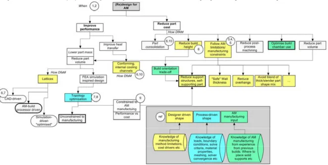
Figure 1 visualises a part of the research field in AM. Some references to literature [1-10] are in circles. Yellow boxes indicate normally designer-driven methods, blue shows process-driven design. Bold boxes are methods used for redesign in this case study.
2. How to design for AM – process driven and designer driven processes
Two different classes of design methods,process driven shape anddesigner driven shape are classified below.Process driven shape focuses on reducing manual interaction with a human designer to reduce design time and/or improve design performance. Designer driven shape is a process with a human designer driving the shape, contributing with knowledge about manufacturing to avoid costly serially produced parts. Both methods will have to consider the AM manufacturability aspect, balancing performance increase and per-part cost in series production.
2.1. Process-driven shape
Process driven shape in the form of topology optimization is a method that can take advantage of AM’s shape complexity capability to increase part performance. Some topology optimising codes provide symmetry constraints to improve manufacturability by reducing the shape freedom for
the iterative solver [11]. Leary et al. showed that it possible to trade-off support structure build up vs. topology optimisation algorithms, reducing printing to half at the expense of 15% increase in mass using a plastic printer [9].
In this case study,Inspire [11] is used to create an optimal shape that is unconstrained by manufacturing symmetry conditions. The engineer needs to know Finite Element Simulation (FEA) and related skills in addition to accurate loads in order to get reliable results.
2.2. Designer driven shape
Designer driven shape is manually driven by a human designer. The goal is often to reduce part cost by using the designer’s knowledge about a chosen manufacturing method. Describing the manufacturing method capabilities such as material properties, dimensional accuracy and cost drivers, together with a dialogue with an AM manufacturer is often enough to get designer-driven shaping processes going. PBF is a layer-by-layer process that gives result depending on build direction. A design-manufacture process would, once AM has been selected as a preferred manufacturing method by using knowledge of the methods strengths and weaknesses, include steps like;
1. Select a build direction (reduce build height if printing few, pack build chamber as full as possible if printing many, reducing build height per part)
2. Add allowance material on to-be-machined surfaces 3. Change geometry if possible to
3.1. Make the design self-supporting, reduce support structure build-up
3.2. Increase probability of correct build by using experience of AM builder and academic research 3.3. Integrate non-moving parts of same material into one
part
3.4. Reduce part volume to decrease build time
Some of the topological constraints of PBF are captured in the build pre-processing. Some are experience-based where
research studies [3-5] can be used to avoid build problems. Input to the design process sometimes includes estimated loads. In these cases prototypes are manufactured and must be tested for requirement fulfilment in a relevant environment. 3. Redesign of beam for AM
3.1. Method
An existing part with was selected for redesign for AM. The part is man carried and part of a non-flying application so mass can be reduced without costly flight tests. The design goal is to reduce part volume to both reduce cost and improve man portability. The part fit inside the build chamber but is originally manufactured in magnesium which does not exist in powder form commercially, so we compare results as if the old design was manufactured in aluminium. To compare series cost between the old and new designs, the AM build chamber was packed with the maximum amount of parts all sharing one powder deposit cost for the build height.
Lattice design was done in Materialise Magics [12], a common AM pre-processor, using theOctet Truss lattice with a 10mm cell size. The design space used no outer wall. Since
Magics cannot vary cell size independently the strut diameter became approximately 1.7mm. Topology optimisation was done inSolidThinking Inspire. Loads of 1500N from the top and 500N from the side and constraints were assigned to the interface volumes. Material properties for AlSi10Mg were created and applied. Solution criteria were to maximise stiffness while reducing mass. Additional shape studies were added when the question “how to reduce cost and mass of the interface spaces” was raised. Could lattice and topology optimisation be combined? The interface spaces have fit requirements on outer surfaces, but they need not be solid. The two ends of the beam was then internally latticed with a wall thickness of 2 mm and joined to a process-driven, optimised design space in the middle. This alternative will create the absolute minimum part volume and part cost.
The design and interface spaces generated in the CAD domain are seen in figure 2 with sub volume definitions. STEP data export was used to let Magics create a high accuracy tessellation for smooth outer interface volume surfaces. For the lattice design, two connecting sheets above and below the design space was kept as an I-beam approach to improve stiffness. The topology optimisation did not have these sheets.
Figure 2. Input to redesign for AM using topology optimisation and lattices
Part cost estimation is done using print time simulations on a Selective Laser Melting (SLM) EOS M290 machine with a 30μm per layer AlSi10Mg powder. Only cost due to print time (assuming 120€/h machine cost) is included. Real part cost would be slightly higher due to added powder cost and post process machine cutting of the interface volumes.
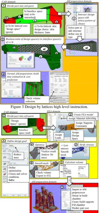
The basic steps of designer-driven shape through lattice design inMagics are shown in figure 3. The basic steps of process driven shape through topology optimisation using
Inspire are shown in figure 4.
Figure 3 Design by lattices high level instruction.
Figure 4 Design by topology optimisation high level instruction
3.2. Results
Selecting most economical build direction from series production perspective was done in cooperation with an AM printing firm. Due to part size (bounding box dimensions 280x60x110mm) and build volume size, (EOS M290 build volume 250x250x350mm) the most economical build volume utilization was in a standing configuration as seen in figure 5.
Figure 5. Build orientation comparison
Three design alternatives are presented in figure 6. The original cast design, if it was to be printed (blue), is showing the internal support effect that a designer for AM would like to remove to reduce cost. By altering the stiffener angles they become self-supporting (green) and reduced print time from 16.6h/part to 15.0h/part for 8 parts. AM shape complexity of designer-driven lattices (red) makes the design space self-supporting but prints slower than the modified cast topology at similar part volume. The combined effect of process-driven shape of topology optimisation of the design space and internally generated, designer-driven lattices on the interfaces spaces (yellow), provides the lowest part volume.
Figure 6 The yellow beam combines lattices and topology shapes, green beam only modifies some angles to reduce internal support build-up, and the red beam uses lattices to
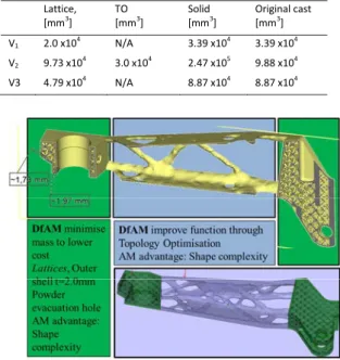
reduce the volume of the load bearing design space Table 1 summarises the volumes V1-V3 from figure 2 and
compares them to the original design. Figure 7 shows a cut
view of the combined lattice + topology optimized (TO) design. Table 2 compares print time related cost and masses of the redesigns to the original design.
Table 1. Design space and Interface space volumes
Lattice,
[mm3] TO[mm3] Solid[mm3] Original cast[mm3]
V1 2.0 x10⁴ N/A 3.39 x10⁴ 3.39 x10⁴
V2 9.73 x10⁴ 3.0 x10⁴ 2.47 x10⁵ 9.88 x10⁴
V3 4.79 x10⁴ N/A 8.87 x10⁴ 8.87 x10⁴
Figure 7. Combined designer-driven lattice on interface spaces and process-driven shape on design space to create
optimal mass reduction Table 2. Part volume and cost comparisons
Original design Latticed design space, solid interface TO design space, solid interface TO design space, latticed interface Total part volume [mm3] 2.2 x10⁵ 2.2 x10⁵ 1.5 x10⁵ 0.9 x10⁵
Total part mass [kg] 0.4 (Mg) 0.6 (AlSi10Mg) 0.6 (AlSi10Mg) 0.4 (AlSi10Mg) 0.25 (AlSi10Mg) Part cost [€/pcs for 8pcs/chamber] 50 (cast + machined) 2000 (AM print cost) 1850 (AM print cost) 1650 (AM print cost) 4. Discussion
The results from the redesign show that choosingwhen to redesign for AM is important. In this case, the lowered mass came at a large increase in per-part cost. Some customers and products could accept such a cost increase due to increased performance. The customer benefit of 0.15 kg less mass in this case is not valued at 1600€ cost increase per part. Design guidelines on how to improve part performance is industry and product specific. Different industries makes different trade-offs when it comes to part cost vs part performance. Industries where performance is more important than part cost, where series volumes are low, where the use of tough materials increase performanceand reduce print times due to
less volume being printed, are more likely to learn design for AM in industry-specific ways.
An important skillset in creating low mass products using process-driven shape through topology optimization or FEA driven processes is the knowledge of loads and other dimensioning criteria. In this case, the loads had to be assumed since the original design used a designer-driven design-test approach and loads were missing. A designer, who is used to drive shape through CAD modelling, may not have the necessary analysis skills or software, to drive shape through topology optimisation. In a real life industrial development, the design tasks as showed here would probably be separated into design and optimisation where the first design step would create a max volume model according to interfaces and allowed space, and in a second step, simulated and optimised by a FEA skilled engineer. In order to constrain a topology optimisation to mimic the manufacturing constraints of AM, a build direction would have to be chosen, and struts in need of support structure would have to be penalized during the iterative solve. In this case, either the design space or the loads were not asymmetrical enough to generate an advanced shape. The result was instead similar to a square, hollow tube shape which in retrospect is understood due to the dual direction load beam bending condition.
Additive manufacturing can support a test based development and verification process by supplying fast prototypes. The designer has a need to create prototypes for functional tests early since loads might not be known, or the skillset of FEA processes are missing. Almost immediately, a manufacturing method needs to be chosen, and to have reduced lead time, preferably a tool less method is chosen during development to reduce lead time.
The lattice design did not reduce part volume due to the choice of lattice pattern.Magics (version 19) does not provide the possibility to vary cell size and strut cross section independently. It does not allow lattice patterns to conform to non-cubic design spaces. More advanced lattice designs would have to be done in CAD or other tools likeWithin [13]. It also printed slower than the modified cast design probably because of suboptimal default print strategies of the lattices. The lattice design would in this case have to be manufactured and tested for performance sinceMagics do not integrate to FEA likeWithin does. When loads are uncertain in value or direction, using lattices could be a beneficial design method compared to topology optimisation. Defining design elements in the manufacturing domain creates ambiguity of what is the design master. However, the speed and ease of designing lattices inMagics to predict mass reduction possibilities is an advantage. Boolean operations with lattice patterns in Magics in this study were done in a few minutes. A CAD-driven Body Centred Cubic lattice with a strut-diameter of 1.5mm with 10mm cell size was created that reduced the volume of the design space as compared to the lattice shown in table 2. Intersecting the pattern with the design space created >18,000 BREP-surfaces with a CAD file size exceeding 600Mb with impractical rebuild times. When changing the lattice dimensions, rebuild would sometimes fail due to Boolean operations failing to complete. More work would have to be
done in order to successfully create a conforming, practical lattice design in the CAD domain.
The part volume could be reduced further by changing material to titanium with better tensile properties relative density than aluminium. Printing the part in titanium and Electron Beam Melting (EBM) would decrease part cost due to less material is needed to carry the same loads and faster print speeds than SLM. Powder evacuation from internal lattices inside the interface spaces would however prove challenging.
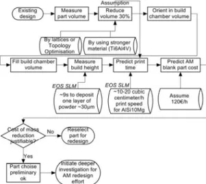
The results show that reducing part volume keeping the bounding box dimensions to early predict print cost is needed to select parts for redesign that can carry the assumed increased part cost. Figure 8 shows a cost prediction model that can give insight into part cost using rough order of magnitude figures for print time related costs. Using this model on a 30% reduced volume of the original cast design results in a print-time cost per part of 1300€-2200€ that could be used to quickly decide if redesign is worth the investment.
Figure 8. Cost estimation part selection for redesign for AM process
Figure 9 shows the similarities and differences between the two design methods shown in this study.
5. Conclusions
How to design for AM was divided into two classes, process-driven and designer-driven shape. Process-driven shape through analysis-driven, iterative processes creates customer value by increased performance. Loads and dimensioning criteria together with analysis knowledge need to be known. A designer-driven design method by lattices in the manufacturing domain may also reduce volume and thus printing time and part cost. However, lattices are not easy to analyse for performance due to geometrical complexity and that the AM domain sometimes uses distorted triangles. The redesigns became more than 30 times more expensive to manufacture than the original design, suggesting a need to do preliminary cost estimations to select parts for redesign and knowing whether a performance increase can allow an increased manufacturing cost.
6. Acknowledgements
The authors gratefully thankProduction2030, the strategic programme for production research and innovation in Sweden and the Knowledge Foundation, for financial support. Thanks also go toLasertech for providing build time simulations of the designs.
7. References
[1] Christoph Klahn, Bastian Leutenecker, Mirko Meboldt Design for Additive Manufacturing – Supporting the Substitution of Components in Series Products, Procedia CIRP 21 2014, 24th CIRP design conference [2] Christian Lindemann, Ulrich Jahnke, Thomas Reiher, Rainer Koch,
Towards a sustainable and economic selection of part candidates for Additive Manufacturing, Rapid Prototyping Journal 2015 vol21 [3] Eleonora Atzeni, Alessandro Salmi, Study on unsupported overhangs of
AlSi10Mg parts processed by Direct Metal Laser Sintering (DMLS), Journal of Manufacturing Processes 20 (2015) 500–506
[4] Guido A.O. Adam, Detmar Zimmer, On design for additive manufacturing: evaluating geometrical limitations, Rapid Prototyping Journal 21/6 (2015) 662–670
[5] J. Kranz, D. Herzog, C. Emmelmann, Design guidelines for laser additive manufacturing of lightweight structures in TiAl6V4, Journal of Laser Applications 2015 vol27
[6] John Schmelzle, Eric V. Kline, Corey J. Dickman, Edward W. Reutzel, Griffin Jones, Timothy W. Simpson, (Re)Designing for Part Consolidation: Understanding the challenges of Metal Additive Manufacturing, Journal of Mechanical Design, November 2015, Vol 137 [7] Hayden K. Richards, David Liu, Topology Optimization of
Additively-Manufactured, Lattice-Reinforced Penetrative Warheads, 56th AIAA/ASCE/AHS/ASC Structures, Structural Dynamics, and Materials Conference 2015, AIAA # 2015-1430
[8] Konstantinos Salonitis, Saeed Al Zarban , Redesign Optimization for Manufacturing Using Additive Layer Techniques, Procedia CIRP 36 (2015) 193-198
[9] Martin Leary, Luigi Merli, Federico Torti, Maciej Mazur, Milan Brandt, Optimal topology for additive manufacture: A method for enabling additive manufacture of support-free optimal structures, Materials & Design 2014 vol 63, 678-690
[10]http://www.americas.gecapital.com/GECA_Document/Additive_Manufa cturing_Fall_2013.pdf page 4, visited 2016-04-12
[11] Inspire, SolidThinking.com, http://www.solidthinking.com/ProductOverview.aspx?item=Inspire Overview&category=Products visited 2016-02-09 [12] http://software.materialise.com/magics, visited 2016-02-09 [13] Within, http://www.withinlab.com/new_index.php, http://www.autodesk.com/products/within/overview visited 2016-02-09 Figure 9. Lattice and Topology optimisation DfAM design processes