using Physical Analogy
for Consistent Image Alignment
by
Manuel Guillén Gonzalez
Thesis submitted to the University of Central Lancashire in partial fulfilment of the requirements for the degree of
Doctor of Philosophy
October 1999
The work presented in this thesis was carried out in the Department of Engineering and Product Design at the University of Central Lancashire,
I declare that while registered with the University of Central Lancashire for the degree of Doctor of Philosophy I have not been a registered candidate or enrolled student for another award of the University of Central Lancashire or any other academic or professional institution during the research programme. No portion of the work referred to in this thesis has been submitted in support of any application for another degree or qualification of any other University or Institution of learning.
and to Reyes
I would like to thank my director of studies Dr. Phil Holifield and my second supervisor Dr. Martin Varley for their encouragement and guidance through all stages of this project.
I am grateful to Professor Trevor J. Terrell for his support and faith in me in the early stages of the project.
I would like to thank Dr. Martyn Shaw for his help with VRML.
The support of the University of Central Lancashire to this research project is gratefully acknowledged, and particularly that of the staff in the Department of Engineering and Product Design.
I thank God for everything He does in my life, particularly for making this work possible.
The research contained in this thesis is an investigation into mosaic construction. Mosaic techniques are used to obtain images with a large field of view by assembling a sequence of smaller individual overlapping images.
In existing methods of mosaic construction only successive images are aligned. Accumulation of small alignment errors occur, and in the case of the image path returning to a previous position in the mosaic, a significant mismatch between non-consecutive images will result (looping path problem). A new method for consistently aligning all the images in a mosaic is proposed in this thesis. This is achieved by distribution of the small alignment errors. Each image is allowed to modify its position relative to its neighbour images in the mosaic by a small amount with respect to the computed registration.
Two images recorded by a rotating ideal camera are related by the same transformation that relates the camera's sensor plane at the time the images were captured. When two images overlap, the intensity values in both images coincide through the intersection line of the sensor planes. This intersection line has the property that the images can be seamlessly joined through that line.
An analogy between the images and the physical world is proposed to solve the looping path problem. The images correspond to rigid objects, and these are linked with forces which pull them towards the right positions with respect to their neighbours. That is, every pair of overlapping images are "hinged" through their corresponding intersection line. Aided by another constraint named the spherical constraint, this network of self-organising images has the ability of distributing itself on the surface of a sphere.
As a direct result of the new concepts developed in this research work, spherical mosaics (i.e. mosaics with unlimited horizontal and vertical field of view) can be created.
Abstract I
CHAPTER 1 INTRODUCTION 1
1.1 Background I
1.2 Aim of the Research 5
1.3 Overview of the Thesis 5
CHAPTER 2 IMAGE ACQUISITION 7
2.1 Introduction 7
2.2 Conventional Camera Technology 7
2.2.1 Image Sensor 7
2.2.2 Field of View and Focal Length 8
2.2.3 Lens Aperture 8
2.2.4 Depth of Field 9
2.2.5 Shutter Speed 10
2.2.6 Video Fields 10
2.2.7 Automatic Gain Control (AGC) 11
2.2.8 Lens Distortion 11
2.2.9 The Ideal Camera 12
2.2.10 The Human Eye 13
2.3 Special Devices for Panoramic Image Acquisition 13
2.3.1 Panoramic Cameras 13
2.3.2 Omnidirectional Cameras 14
2.3.3 Non-frontal Imaging Camera 15
2.4 Summary 16
CHAPTER 3 MOSAIC CONSTRUCFION 17
3.1 Introduction 17
3.2 Image Registration 17
3.2.3.1 Feature Space 23 3.2.3.2 Similarity Measure 23 3.2.3.3 Search Space 24 3.2.3.4 Search Strategy 24 3.2.4 Unwanted Elements 26 3.2.4.1 Motion Parallax 26 3.2.4.2 Lens Distortion 26 3.2.4.3 Moving Objects 27 3.2.4.4 Motion Blur 28 3.3 Image Integration 28 3.3.1 Image Blending 28
3.4 Voronoi Diagrams and Delaunay Triangulation 30
3.5 Summary 34
CHAPTER 4 THE LOOPING PATH PROBLEM AND PROPOSED SOLUTION 35
4.1 Introduction 35
4.2 Previous Approaches 36
4.2.1 Registering New Image with Current Mosaic 37
4.2.2 Registering Sub-mosaics 37
4.2.3 Distribution of the Error 37
4.2.4 Simultaneous Registration of All Images 38
4.3 Proposed Solution to the Looping Path Problem 39
4.4 Minimisation using Physical Simulation 42
4.4.1 Why Physical Simulation? 43
4.4.2 Physical Simulation 44
4.4.2.1 The Rigid Body 44
4.4.2.2 Coordinate Systems 44
4.4.2.3 Linear Equations of Motion 46
4.4.2.4 Angular Equations of Motion 47
4.4.2.5 Simulation Engine 48
4.4.2.6 Forces 49
4.4.2.7 Euler's Integration Method 49
4.4.4 The Hinge Constraint 55
4.4.5 Stability and Convergence of Image System 58
4.4.5.1 Spring-Mass System 58
4.4.5.2 Damped Spring-Mass System 60
4.4.5.3 Image System - 65
4.4.5.4 Example 68
4.5 Summary 70
CHAPTER 5 PLANAR SCENE MOSAIC 71
5.1 Introduction 71
5.2 Image Acquisition 71
5.3 Implementation of Image Registration 73
5.3.1 Transformation Model 73 5.3.2 Feature Space 74 5.3.3 Similarity Measure 75 5.3.4 Search Space 77 5.3.5 Search Strategy 77 5.3.5.1 Hierarchical Pyramids 78 5.3.5.2 Rotation 80
5.3.5.3 Image Registration with Progressive Complexity Models 81
5.3.5.4 Subpixel Accuracy 84
5.4 Physical Model for the Planar Mosaic 85
5.5 Image Integration 86
5.6 Experimental Results on Document Mosaic 86
5.7 Summary 93
CHAPTER 6 SPHERICAL MOSAIC 94
6.1 Introduction 94
6.2 Image Registration Considerations 94
6.3 Partial Spherical Mosaic Mapped to a Plane 95
6.3.1 Image Acquisition 95
6.3.5 Summary 99
6.4 Double Band Panoramic Mosaic 99
6.4.1 Image Acquisition 100
6.4.2 Physical Model for Image Alignment 101
6.4.2.1 The Spherical Constraint 103
6.4.2.2 The Same Plane Constraint 107
6.4.2.3 Hinge Parameters 108
6.4.2.4 Effects of Damping on Convergence 109
6.4.2.5 Voronoi Tessellation and Delaunay Diagram on the Sphere 110
6.4.3 Image Integration 110
6.4.4 Results 111
6.5 Full Spherical Mosaic 114
6.5.1 Image Acquisition 114
6.5.2 Physical Model for Image Alignment 115
6.5.3 Image Integration and Display 120
6.5.4 Displaying Results 121
6.6 Summary 122
CHAPTER 7 CONCLUSIONS & FURTHER WORK . 127
7.1 Contributions 127 7.2 Further Work 129 7.3 Summary 131 REFERENCES 132 APPENDIX A CD-ROM 139 APPENDIX B PUBLICATIONS 141 v
Chapter
1
INTRODUCTION
1.1 Background
Mosaics are images with a large field of view obtained by assembling two or more individual overlapping images. Historically, the most significant application for image mosaicing is in the development of aerial images [Wolf, 1974] and satellite images [Horii, Oshima and Hirao, 1995], [Milgram, 19751. These mosaics are commonly used as substitutes for maps and also for remote sensing applications. With the arrival of digital photography, new applications for mosaicing were created [Milgram, 1975] [Milgram,
1977] [Peleg, 19811 [Burt and Adelson, 1983a]. The list of applications using mosaic techniques is extensive today, a typical application being the creation of panoramas (images with a 360° horizontal field of view).
Mosaics can be useful where the image sensor does not have sufficient pixel resolution to provide a single image with the level of detail needed. The attainable resolution in a mosaic is essentially unlimited [Szeliski, 1994a]. Since the images can be acquired using any optical technology (from microscopy, through hand-held video cameras, to satellite photography), the range or scale of the scene being reconstructed is not an issue. Analogously, the field of view is not a limiting factor in a mosaic. Panoramas have a 3600 horizontal field of view, and full spherical mosaics with an unlimited vertical field of view are also possible.
The use of video as a source of images for constructing mosaics has been recently investigated by many researchers [Giaccone, Greenhill and Jones, 1998], [Burt, Hansen and Anandan, 1996], [Irani, Anandan and Hsu, 19951, [Mann and Picard, 1995], [Peleg and Herman, 1997b], [Rousso, Peleg and Finci, 1997b], [Bender, 1993], [Szeliski,
reasons. Considering the high frame-rate of video, typically 25 frames per second, copious amounts of images are available, and the overlapping —indispensable to align the images— between consecutive frames is intrinsically large. In addition, mosaics can achieve image sizes far beyond the resolution of individual video images, and detail can be maintained over an unlimited field of view, therefore enhancing the quality of the images.
Mosaics have a great deal to offer in virtual reality applications. In a virtual reality experience, the main subjective measure of image quality used in the assessment of geometric rendering systems is the degree with which the resulting images are indistinguishable from photographs. One of the biggest bottlenecks standing in the way of widespread virtual reality applications is the slow and tedious model-building process if the models are to resemble the complex and detailed reality with a degree of fidelity. Image-based rendering is an efficient way to create a virtual reality experience. Instead of building and rendering a complete 3D model of the environment, i.e. using polygons, a collection of images is used to render the scene while supporting virtual camera motion. The progression toward image-based rendering systems was initially motivated by the desire to increase the visual realism of the approximate geometric descriptions by mapping images onto their surface (texture mapping) [Heckbert, 1989]. Next, the images were used to approximate global illumination effects (environment map, that is, a 3600 spherical image of the environment, to correctly generate reflections from shiny objects [Greene, 1986]), and, most recently, systems have been developed where the images themselves constitute the significant aspects of the scene's description [Chen and Williams, 1993] [Smooth Move].
The class of virtual reality applications which attempt to recreate true reality as convincingly as possible commonly use an environment map which serves as a backdrop and to correctly generate reflections from shiny objects [Greene, 1986]. Examples of these applications include flight simulators, which were among the earliest uses of virtual reality, computer games, medical simulators, visualisation tools, interactive 3D walkthroughs of existing buildings for re-modelling or selling [Szeliski, 1994a]. Walkthroughs of historic building (e.g. palaces or museums) can be used for educational and entertainment purposes. In addition, a museum scenario might include the ability to
look at individual 3D objects such as sculptures, and to bring up related information in a hypertext system [Miller et al., 1991]. Panoramic images, also ca/led immersive photographs, are already being used by wopW and travel companies and museums, to give virtual tours on computers or kiosks [Eccles, 1999]. Other obvious customers for this new technology are hotels, theme parks, estate agents, film and television location fmding services, and developers of game and education software. It enables them to obtain images from scenes that are not practical to render artificially.
The film and video industry may also benefit from mosaicing. Many film and video sequences are captured by cameras undergoing small rotational and zoom velocities with near zero translation. Under such conditions the projected view volume is free from perspective changes such as occlusions and parallax, and the image sequence may be merged to create a large virtual image [Giaccone, Greenhill and Jones, 1998]. Since successive images within a video sequence usually overlap by a large amount, the mosaic image provides a significant reduction in the total amount of data needed to represent the scene (i.e. video compression). Moreover, mosaics have been recognised as efficient ways of providing complete representation of large video sequences for film and video editing [Irani, Anandan and Hsu, 1995].
Mosaicing makes possible a new generation of tools for the post-production industry. Mosaicing techniques offer the post-production operator, even in small sequences, the opportunity to easily modify viewing trajectories, introduce computer generated elements, stabilise jumpy action or positionally justify action in the view port, create alternative camera trajectories and add new static details into the background sequence [Giaccone, (Jreenhill and Jones, 19981. For instance, custom advertisements can be easily added to the background of a recorded scene, or the same person can be composited into the final video sequence more than once [Bender, 1993].
A representative application that exploits the unlimited resolution of mosaics is in digital recording of paintings, where it is required to store a picture in its highest detail but the format of the image sensor is not large enough to provide the necessary resolution [GUmfistekin and Hall, 1996b]. Particularly useful can be the construction of mosaics using off-the-shelf inexpensive PC cameras. High quality stills and omnidirectional
views can be created without requiring any special (and costly) equipment [Sawhney and Kuinar, 1997].
There are a number of commercial products using image-based rendering systems. Some ([QuickTime VR], [Surround Video] and [Spin Panorama]), use cylindrical images with a limited vertical field of view (e.g. images 2496 by 768 pixels in size are used in QuickTime VR applications).
Certain panorama programs (e.g. Quick Time VR) can assemble a panorama from a series of still photos taken with an ordinary camera. The alignment between overlapping images is not fully automatic, and does require some intervention by the developer. Among other things, the program must be instructed whether the camera was oriented vertically or horizontally (to include as much vertical space as possible the camera is usually turned sideways) and how much overlapping area between frames should be analysed when the edges are joined together. In other programs the image alignment is fully manual (e.g. Spin Panorama). In all cases the programs blend exposure differences between overlapping frames. Surround Video, on the other hand, requires a special panoramic camera that records a panoramic image in one single piece of film (these will be discussed in 2.3.1), eliminating the mosaicing process.
Panorama viewers are used to render distortion-free views of portions of the panoramas, according to user input Any portion of the 3600 panoramas can be viewed: the image on the screen represents a small arc of the entire 360° (usually about 70°). A virtual camera pans the image left or right in a complete circle and zoom in for a closer look at small details, although vertical scrolling is limited to the field of view captured by the camera's lens. Panoramas are interactive in ways that are impossible without a computer. For instance, developers can link panoramas together, so users can change viewpoints by clicking on predeflned hot spots or examine certain objects in more detail.
Newer systems support full spherical maps (e.g. [Omnicam], [Smooth Move], [Be Here], and [Rea1VR]), although these programs require omnidirectional cameras (see 2.3.2) to acquire the images or, alternatively, computer generated images. Panoramic videos are an exciting experience that has become possible using a personal computer. In a panoramic
video, each image of the video sequence is an omnidirectional view. The user can move in a predetermined path through the scene while looking in any direction.
1.2 Aim of the Research
This thesis describes research into the problem of mosaic construction. Composing mosaics from a number of overlapping images is a problem of image registration. Existing registration algorithms are designed to align pairs of images, but cannot be used with more than two images simultaneously. It will be shown that the accumulation of small alignnent errors may become apparent in the mosaic regardless of the accuracy attained in the registration process.
The prime motivation of the research project described in this thesis was to develop new techniques for the construction of mosaics. Since error-free image registration techniques do not exist, it is the intention of the author to develop a new technique, based on existing imperfect registration methods, for consistently aligning all images which form part of a mosaic.
In achieving the solution, a new type of mosaic will be possible. The spherical mosaic, composed from images obtained by panning and tilting a camera, represents an omnidirectional view of the scene.
1.3 Overview of the Thesis
The thesis is organised to present material in a progressive manner. It begins by introducing the concept of a mosaic and its applications.
Chapter 2 examines the operation and limitations of the conventional camera when used for the acquisition of images for mosaic construction. Subsequent sections discuss a set of specialised panoramic and omnidirectional cameras.
In Chapter 3, image registration and image integration techniques are described as the
basic steps involved in mosaic construction. The types of mosaics that can be created for
each case of camera motions are also presented.
Chapter 4 introduces the
Looping Path Problem,and a discussion of previously proposed
solutions. A novel solution is offered which uses a physical analogy to distribute the
accumulated alignment error in the mosaic. The concepts and equations for a physical
simulation are reviewed and a physical model for the mosaic is presented.
Chapter
5describes the implementation of the image registration technique adopted in
this project. Results on planar scene mosaics are presented.
Chapter 6 discusses, in three progressively complex experiments, the constraints
developed for the physical model of the spherical mosaic. In the last experiment the
results on the spherical mosaic are presented.
In Chapter 7, conclusions for this thesis are presented. This summarises the original
contributions to knowledge made in this research, and recommends improvements and
future directions which can be investigated.
In this thesis the following convention is used: variables printed in bold denote vectorial
magnitudes (e.g. a, F), where variables in italics (e.g.
m)are scalar quantities. Bold and
italics are used for matrices (e.g. Sj).
Chapter 2 IMAGE ACQUISITION
2.1 Introduction
In conventional photography, much thought must be given to choice of viewing position, composition, and lighting, while at the scene. This remains true for panoramic image acquisition, with the additional complexity of a wider and generally more assorted scene to be recorded. This chapter explains the operation of the conventional camera and its limitations. Also a set of specialised cameras designed specifically to record panoramic and omnidirectional views is discussed.
2.2 Conventional Camera Technology
Although imaging technology has advanced enormously in the past few years, there are still limitations in image acquisition which are necessary to understand. Obtaining images from the real world requires setting a number of variables to accommodate to each particular scene. Light conditions, distance of objects to the camera, and the motion of both, affect the camera settings if a sharp, focused image is to be obtained.
The following sections describe the variables involved in the image acquisition process and their interrelation. These apply to both still and video cameras, which differ only in sensor type and the fact that video cameras record images repetitively.
2.2.1 Image Sensor
In a still camera, the imaging device is the film. In video and digital cameras, the imaging sensor is generally a Charge-Coupled Device (CCD). A CCD is a two-dimensional array of transistors sensitive to light, which convert the light intensity into electrical signals. Each of these transistors corresponds to a pixel in the image. Colour sensors are implemented either using three CCDs, one for each colour component (red,
green and blue), or using one CCD where, for each pixel, the transistors are arranged into groups of three, each transistor sensitive to a colour component.
2.2.2 Field of View and Focal Length
The field of view (a) is the coverage angle of a camera (see Figure 2-1). In a conventional camera, the horizontal field of view is wider than the vertical field of view. The focal length
(7)
is the distance between the sensor plane and the optical centre of the lens. The zoom or magnification of the lens is modified by varying the focal length. The field of view and the focal length are related by the following expression,a = 2tazf'(k L2f Saisor (CCD) diaphra F;
field of view (& focallengthQ) opticolcentre
Figure 2-1 Simplified camera model showing the field of view and the focal length.
2.2.3 Lens Aperture
The diaphragm, also called iris, is a device for controlling the amount of light passing through the lens system. This is constructed from a series of flat, interleaving metal blades, which together form a central hole of adjustable size. The area of this aperture
controls the brightness of the image the sensor receives from the scene. It can be changed either manually by turning a ring on the lens barrel or electronically in cameras provided with this feature.
(1)
The influence of the lens aperture is twofold:
It determines how much light from the scene reaches the sensor.
It affects the depth of the scene that appears sharp and will be explained in section 2.2.4.
In general, the lens aperture is determined principally by the brightness of the scene. Strong sunlight may require a reduced aperture, dim light demands a wider aperture.
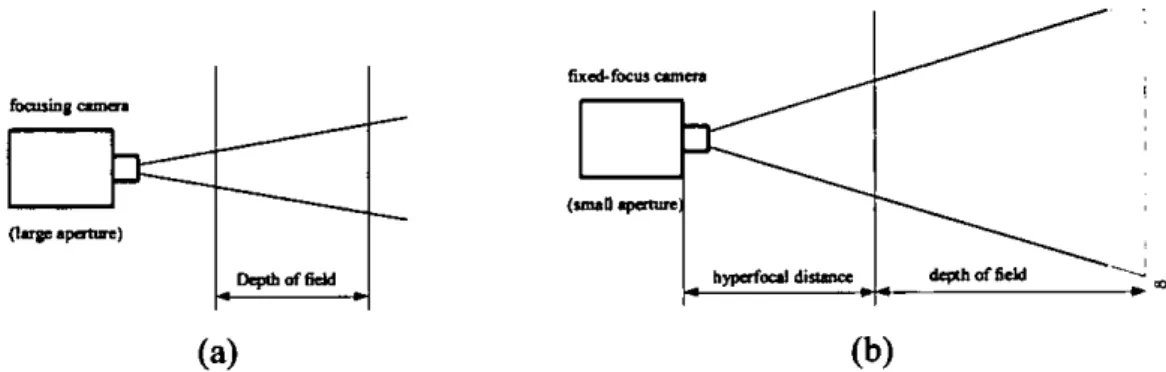
2.2.4 Depth of Field
The camera lens can focus sharply only for one distance at a time. Nearer and farther than that focused plane, the defmition (clarity) deteriorates until eventually detail can be no longer discerned at all. However, objects nearer and further than the focused distance still appear quite well-defined. This region of sharp reproduction is known as the depth of field. At larger lens apertures, the lens gives less depth of field, at smaller apertures, this
sharp zone steadily increases.
The scene before the camera is usually three-dimensional; it has depth. So, as the subject (and/or the camera) moves within the scene, the camera's focus control needs to be adjusted continually to keep the selected part of the scene sharp.
Fixed-focus cameras represent a simplified compromise design. A fixed-focus camera has its focus set to the hyperfocal distance. Everything will be reasonably sharp from half this distance (nearest point), away to infinity. The hyperfocal distance is proportional to the square of the focal length and to the lens aperture, i.e. a short hyperfocal distance is achieved with a small focal length (i.e. large field of view) and a small lens aperture (see Figure 2-2). As a fixed-focus camera only works with a comparatively small aperture to provide depth of field, light intensities must be high. Besides, for short-distance subjects (i.e. close shots), the fixed-focus camera becomes unacceptably defocused. However, they make operation easier, and provide an overall clarity that is sufficient for many applications.
fixed-focus snaa foa'sing .
(w'a
distance I d,thof5c1d
(a) (b)
Figure 2-2 Objects within the depth of field will appear in focus. (a) Focusing camera. (b) Fixed-focus camera.
2.2.5 Shutter Speed
Shutter speed, also called exposure time, refers to the lengtliof time the sensor is exposed to the light from the scene for one frame. For film, the shutter is a mechanical device, while in a CCD the shutter speed is controlled electronically, common speeds ranging from 1150supto 1/2000s.
Large exposure times will cause moving objects, or the entire scene in the case of a moving camera, to appear blurred (motion blur). When photographing fast moving scenes, a small exposure time is a must. The exposure time is also determined by the brightness of the scene. Bright scenes may require less exposure time than dim scenes. The exposure time is normally set in conjunction with the lens aperture to accommodate to a particular scene brightness. Any change in the lens aperture must simultaneously affect the exposure.
2.2.6 Video Fields
An interlaced video frame is composed of two fields, each one containing half of the scan lines needed to make up one video frame. That is, the first field contains every other scan line of the frame, and the second field contains the rest of the lines. A large TV screen that is updated at 25 frames per second would flicker, i.e. the image would begin to fade away before the next one was drawn on the screen. By using two fields, each containing one half of the information that makes up the frame and the fields being drawn on the screen consecutively, the field update is 50 fields per second. At this update rate, the eye blends everything together into a smooth, continuous motion.
In the acquisition process, the video camera registers the fields sequentially (i.e. one field after the other), and since there is a lag between the field acquisitions, motion artifacts may occur when the two fields are displayed together. A common procedure to achieve a motion-free image is to use only one field per frame and discard the other, although this reduces the available resolution by half
Fields only exist for interlaced scanning systems, that is, most video cameras except progressive scan video cameras, which are designed to capture the whole frame at once, and digital still cameras, which register non-interlaced images.
2.2.7 Automatic Gain Control (AGC)
Video cameras and digital cameras can adjust the amplification of the signal received from the sensor (CCD) to accommodate different illumination conditions. The intensity is integrated over the image and this information is used to automatically adjust its brightness. If dark and bright scene elements are combined in the same image (i.e. large dynamic range), for instance, an image of a dim room with a blazing vista of snow peaks and clear blue sky seen through a window, the contrast and therefore the details of the image are reduced, particularly in the very bright and dark regions. For the same scene, another view of the room without the window will present distinctive detail.
2.2.8 Lens Distortion
The lens is a complex item that has inherent distortions and its quality is directly related to cost. Lens aberrations are the deficiencies in image due to the lens, and include spherical aberration, coma, astigmatism, curvature of field, distortion of the image and chromatic aberration [White, 1982]. Distortion of the image (barrellpincushion) is due to the magnification of the lens being dependent upon the direction of the incident rays.
Coma
is caused by the differences in the power of various annular zones of the lens (i.e. from the thick to the thin part) and occurs when the parallel rays are at an angle to the principal axis. This results in the image produced by the marginal rays having a reduced brightness.2.2.9 The Ideal Camera
The camera model generally used in computer vision is the ideal pinhole camera [Mann and Picard, 1994c], [Bender, 1993], [Gumustekin and Hall, 1996b]. It assumes infinite depth of field, and that light travels in straight lines (ignores diffiaction).
The use of this model can be justified when first, the objects in different depths recorded by the camera are in focus (which is the case when the diameter of the aperture of the camera is very small). Second, there is no significant distortion caused by physical characteristics of the optical elements (i.e. no barrel/pincushion distortion). And third, the distance from the camera to the objects is much larger than the distance between the film plane and the diaphragm.
The camera projects a 3D scene onto a 2D plane (see Figure 2-3). If the coordinates of the objects in the scene is known, say (xO, yo, zo), the corresponding point in the image (xi, )') is given by:
-fx0 -f;'
Xi (2)
zo f
mu
Figure 2-3 Pinhole camera model.
2.2.10 The Human Eye
The human visual system is one of the most complex in existence. It consists of an eye that transfonns light to neural signals (see [Lim, 1990] for a more comprehensive description). Functionally, the eye is a device that gathers light and focuses it on its rear surface. From the point of view of image mapping, the most important difference between the human eye and a camera is the shape of the surface of projection. In the eye, it is approximately spherical, while a camera sensor is planar. The projection of images onto a planar sensor yields to projective distortion (see Figure 3-Id), which is not applicable to the spherical projection surface of the human eye.
2.3 Special Devices for Panoramic Image Acquisition
There are several variations of the conventional camera worth mentioning in this thesis (panoramic cameras, omnidirectional cameras and non-frontal imaging cameras). Either enlarging the field of view, or reducing the focusing limitations of a conventional camera, they improve the acquisition process of iminersive images. A discussion on the suitability for different applications follows the description of these devices.
2.3.1 Panoramic Cameras
Panoramic cameras are specially designed to record a cylindrical panoramic image onto a long film strip [Meehan, 1997]. A panoramic camera automatically rotates about a fixed nodal point (i.e. pans 360°) while continuously exposing a strip of film that moves in the opposite direction.
The vertical field of view is not very wide in panoramic cameras. This may be too restrictive for some applications, and only the most expensive models have interchangeable lenses. To digitise the long film strip from a panoramic camera with enough resolution to support high magnifications, an expensive drum scanner that is big enough to accommodate the strip must be used [Halthill, 1995]. Standard film scanners cannot be used, and flatbed scanners are not recommended.
Although the use of a panoramic camera simplifies the acquisition of panoramic photographs, in the digital era alternatives have been proposed to reduce cost and limitations.
2.3.2 Omnidirectional Cameras
An omnidirectional camera can record an omnidirectional view (full 3600 vertical and horizontal field of view) from a single viewpoint. Its implementation uses a conventional camera and a parabolic or pyramidal mirror, which maps a 1800 hemispherical view onto one single image. For a 3600 full view, two cameras facing in opposite directions are used.
[Nayar, 1998] developed a hemispherical video system, called omnicam, combining a standard lens on a video camera with a paraboloid mirror. Two such cameras can be placed back-to-back, without violating the single viewpoint constraint, to achieve an onmidirectional sensor. The only blind spot is at the apex of the parabola where the camera sees itself. Another very wide field of view lens system has been introduced by Be Here Corporation [Be Here], named Portal lens. It captures a 360° by 100 0 aspect ratio image with a single camera [Hamit, 1997]. It uses one large parabolic mirror, and four optical elements (i.e. lenses), which then feed the image to a standard Nikon 24mm camera lens. Images recorded by an omnidirectional camera must be unwrapped in software or projected onto a hemispherical dome, to produce a distortion free view of the scene.
In the creation of immersive images, omnidirectional cameras surpass mosaicing teclmiques in several ways: firstly, by eliminating the composition process of images and possible misalignments and visible seams. They also avoid problems associated with parallax, motion blur and moving objects, and, most important, they can operate in real-time, which makes omnidirectional films possible, with each frame containing a full view.
However, due to the mapping of a hemispherical view onto a flat image the resolution of an omnidirectional image is four times as great for objects seen near the centre of the mirror than at the edges. This inefficient distribution requires a sensor with four times the
useful final resolution. The developers of the "Be Here's Portal" lens recommend using film as an intermediate medium. Film has a higher resolution than most digital cameras (there are some high end cameras that offer better resolution, but they are very expensive), and as much resolution as possible is needed [Hamit, 1997]. On the other hand, mosaics offer essentially unlimited resolution. One of their most attractive applications is the creation of omnidirectional views using off-the-shelf inexpensive PC cameras.
Moreover, mosaicing possesses a range of applications of its own, for which omnidirectional cameras are not suitable. These include video compression and the complete and efficient representation of large video streams [Irani, Anandan and Hsu,
1995]. In the video and film post-production industry, it offers the operator the opportunity to easily modify viewing trajectories, introduce computer-generated elements, stabilise jumpy action, positionally justify action in the view port, and add new static details into the background sequence [Giaccone, Greenhill and Jones, 1998].
2.3.3 Non-frontal Imaging Camera
A non-frontal imaging camera (NICAM) is a camera in which the sensor plane is tilted. Since the sensor plane is at a non-perpendicular angle to the optic axis, different parts of the sensor are focused at different focus depths [Krishnan and Ahuja, 1996].
To create fully focused panoramic images requires individually focused images at every pan angle. For scenes with bright light conditions, the lens aperture can be made small enough to increase the depth of field to near infinity, and using a frontal camera (i.e. conventional camera) is the easiest way to create a panoramic mosaic.
However, if infinite depth of field is not possible (i.e. dark scene or close objects), parts of the scene will appear defocused. Then panning a NICAM is an alternative to obtain a focused panoramic image. The same object will appear in different images and in different focus. For the composition of the mosaic, only the focused areas of the images are used. [Krishnan and Ahuja, 1996] explains a method for the composition of panoramic mosaics using a non-frontal camera.
For scenes where a conventional camera needs to be focused for each image composing the panorama, then using a non-frontal camera might reduce the acquisition lime, although it introduces additional post-processing complexity. For a conventional fixed-focus camera, only dark scenes, and objects too close to the camera are problematic. Practically, most scenes are correctly acquired in focus, in the worst case, at the expense of increasing the exposure time.
2.4 Summary
Understanding the operation and limitations of the real camera is important in image processing applications. Despite technological advances in image acquisition devices, the art of photography, whether using film, digital format or video, requires the photographer to decide on a number of camera parameters (field of view, lens aperture, shutter speed ... ), to accommodate for different scene conditions.
This chapter has covered the interrelation between the factors detennining the quality of images in the acquisition process with real cameras. A set of specialised cameras designed specifically to record panoramic and omnidirectional views was discussed and theft limitations exposed. In next chapter, techniques for mosaic composition will be presented.
Chapter 3 MOSAIC CONSTRUCTION
3.1 Introduction
Mosaicing is the technique used to produce large images by assembling two or more individual overlapping images. The resulting image is called a mosaic, and it has a wider field of view and higher resolution than each of the individual images.
The basic processing steps involved in mosaic construction are well known [Peleg and Herman, 1997a], and can be summarised as follows:
Image registration: Determines the transformation that aligns every pair of overlapping images. The quality of a mosaic directly depends on the quality of the individual alignments between overlapping images. The displacements must be estimated to high precision so that the images can be positioned in the mosaic to a small.fraction of a pixel.
Image integration: Consists of the selection of non-overlapping areas in the images that will contribute to the final mosaic or the combination of pixel intensities from overlapping images. Further blending of neighbour images is necessary to reduce the visibility of seams due to differences in intensities.
In this chapter, the steps and techniques involved in the composition of mosaics are
3.2 Image Registration
Registration is a fundamental task in image processing used to match two or more images taken, for example, at different times, from different sensors, or from different viewpoints [Brown, 1992]. A transformation must be found so that the points in one image can be
related to their corresponding points in the other image. For two images, denoted by 'A
and Jg, where !A(x, y) and JB('X, y) each map to their respective intensity values, the
mapping between the images can be expressed as
JA(X,Y) = IB(AX, Y)) = JB(X,Y) (3)
wheref is a 2D spatial-coordinate transformation, that is, a transformation which maps two spatial coordinates, x and y to new spatial coordinates x' and y'. Thus, image registration is the process of finding the transformation (i.e. function 3) that best aligns two images.
Over the years, a broad range of image registration techniques has been developed for various types of problems, such techniques are reviewed in [Brown, 19921. Particularly, registration techniques have been applied to image mosaicing by [Mann and Picard, 1994c], [Irani, Anandan and Hsu, 1995], [Chen, 1995] [McMillan and Bishop, 1995] and [Szeliski, 1994b] among many others.
3.2.1 Transformation Models
In the simplest case, two images can be related by a pure translation. This is followed in complexity by translations and rotations (rigid transforms, Figure 3-Ib), then scaling, i.e. similarity transfonns, affine transforms (see Figure 3-Ic), and frill projective transforms (Figure 3-1d) (see [Wolberg, 19901 for a detailed survey on transformations). Several authors have suggested using projective transformations for registration of the images in a mosaic [Mann and Picard, 1994c] [Irani, Anandan and Hsu, 1995] [Szeliski, 1994b] [Gumustekin and Hall, 1996b].
Figure 3-1 (a) Original image. (b) Rigid, (c) Affine, and (d) Projective transformations.
The mapping or transformation
fi)
can be expressed in matrix form using homogeneous coordinates to represent points, that is, 2D points in the image plane are denoted as (x, y, w) [Szeliski, 1 994a]. The corresponding Cartesian coordinates are(x/w, y/w). The 2D planar transformations can be described as follows:x' m 1 m 12 m 13 x
= m 21 m 22 m 23 y or
flx,y,
w)=M(xyw)t (4)w' m 31 m 32 m 33 w
where x, y are pixel coordinates,
x '1w', y '1w' are the new pixel coordinates,
mij are the parameters that describe the transformation.
For each case (i.e. rigid, similarity, affine and projective transformation), a different number of parameters m y are necessary to describe the transformation [Szeliski, 1994a]. A rigid transformation model involves only three parameters: two for the translation (Ax, Ay) and one for the rotation (A®. The rigid transformation matrix is as follows.
cosAO —sinj9 Ax
Mnjr sinAO cos4O Ay (5)
0 0 1
where Ax, Jy are the translation components and 40 is the angle of rotation (as shown in Figure 3-2).
Image B
Image A
Figure 3-2 Rigid transformation parameters that align two overlapping images. CA and C8 are the centres of images A and B respectively.
The affine transformation model involves six parameters (6), while the projective transformation model has a general matrix M (4) with 8 degrees of freedom. Note that two matrices are equivalent if they are scalar multiples of each other. This redundancy can be removed by setting m33=1 [Szeliski, 1994a].
m 11 m 12 m 13
Maj,e = m 21 m 22 m 23 (6)
0 0 1
3.2.2 Camera Motion
Mosaics can be created from video sequences recorded by a variety of camera motions. There is a connection between the constraints imposed on the camera motion and the number of parameters involved in the transformation matrix. Hence, for each type of camera motion, a suitable transformation model is required.
The determination of the optimal transformation model for registration depends on the types of variations between the images. [Mann and Picard, 1 994c] identify the cases where the affine model and the projective model correctly describe the relationship between two images from a video sequence.
The affine model applies to:
Case 1. A camera free to worn and to rotate about its optical axis on an arbitrary static scene.
Case 2. An arbitrary planar scene —such as a document or a whiteboard— where the camera is free to zoorn, to rotate about its optical axis and to translate, provided that the plane of the image sensor remains parallel to the planar scene (see Figure 3-3). The affme model, however does not correctly account for camera pan or tilt.
The projective model correctly describes two broader cases:
Case 3. Planar scene free to move arbitrarily, and camera free to move arbitrarily (see Figure 3-4).
Case 4. A camera at a fixed location, free to zoom and to rotate about its optical centre of projection (i.e. camera free to rotate about its optical axis, and to pan and tilt), on an arbitrary static scene (see Figure 3-6). The particular case where the camera can pan but it is not allowed to tilt is represented in Figure 3-5.
Figure 3-3 Camera fixed over a desk with optical axis perpendicular to desk surface. As a document is translated and rotated under the camera, different portions of it becorne visible. Any two frames are related by a translation and a rotation and scale if allowed to zoom.
Figure 3-4 Planar scene and camera free to move arbitrarily. For a camera allowed to change its position (i.e. translation), its orientation (i.e. rotation) and zoom over a planar scene, two overlapping frames are related by a projective transformation.
Figure 3-5 For a camera free to pan about its optical axis, the resulting mosaic can be pasted onto a cylinder.
Figure 3-6 Camera free to zoom, pan and tilt about its optical centre of projection. The resulting mosaic can be pasted onto the interior surface of a sphere.
3.2.3 Image Registration Techniques
[Brown, 1992] classifies image registration techniques according to four major components: feature space, similarity measure, search space and search strategy. Every registration technique can be thought of as a selection for each of these components.
3.2.3.1 Feature Space
The feature space extracts the information in the images that will be used for matching. They can be the pixel intensities, but other features are commonly used such as edges, contours, surfaces, salient features such as corners [Zoghianii, Faugeras and Deriche, 1997] [Capel and Zisserman, 1998], text [Zappala, Gee and Taylor, 1997], lines [Janssen and Vossepoel, 1994], and points of high curvature. Also statistical features such as moment invariants or centroids, and higher-level structural and syntactic descriptions can be used.
The choice of feature space depends on the content of the images to align, since the features to be identified and matched should, first of all, be embodied in the images. When no information on image content is known in advance, such as in a general mosaic application, the use of any particular salient feature and the risk of its absence should be avoided. On the other hand, direct estimation, i.e. based on pixel intensities, has proven to be more practical and robust over feature correspondence based methods since the direct methods typically use all the data and structure constraints in the estimation process [Sawhney and Kumar, 1997].
3.2.3.2 Similarity Measure
The similarity measure determines the relative merit for each test. Typical similarity measures are cross-correlation, sum of absolute differences, and Fourier invariance properties such as phase correlation. Using curves and surfaces as a feature space requires measures such as sum of squares of differences between nearest points.
Cross-correlation measure is the basic statistical approach to registration. By itself, cross-correlation is not a registration method. It is a similarity measure of match metric, i.e. it gives a measure of the degree of similarity between two images. However, there are several registration methods for which it is the primary tool. The cross-correlation
measure is directly related to the more intuitive measure which computes the sum of the differences squared between the two images at each pixel location:
D(f 0) = [IA(x.Y) - I 8 (f(x,y)) (7)
This measure decreases with the degree of similarity since, when the images are superimposed using the transformationJ() for which the two images are most similar, the differences between the corresponding intensities will be smallest. A more efficient class of algorithm was proposed by Barnea and Silverman [Barnea and Silverman, 1972]. They suggested a similarity measure (8) which is computationally much simpler, based on the absolute differences between the pixels in the two images:
D(f 0) = - 1D(I(X,Y))l (8)
Phase correlation has been used to find large displacements between overlapping images [Szeliski, 1994b]. This technique estimates the 2D translation between a pair of images by taking 2D Fourier transforms of each image, computing the phase difference at each frequency, performing an inverse Fourier transform, and searching for a peak in the magnitude image.
3.2.3.3 Search Space
The search space is the set of transformations that is capable of aligning the images. It is the space of all possible transformations. Each transformation candidate is evaluated using the similarity measure. The search continues according to a search strategy until a transformation is found whose similarity measure is satisfactory.
3.2.3.4 Search Strategy
The search strategy decides how to choose the next transformation from this space, to be tested in the search for best transformation. Because of the large computational cost associated with many of the matching features and similarity measures, all possible
transformations can not be tested, and a good search strategy reduces the computational cost of finding the best match.
To reduce the search space, a search strategy such as gradient descent or Levenberg-Marquardt can be used. Unfortunately, they both only find locally optimal solutions. If the motion between successive frames is large, a different strategy must be used to find the best registration [Szeliski, 1994a].
Mother technique commonly used in image processing (image registration, pattern recognition, classification, etc.) to achieve shorter computation times is hierarchical matching (also called pyramidal structures and Laplacian pyramids) [Bergen et al., 19921 [Hansen et al., 1994]. Smaller images are created from the original images by averaging blocks of pixels as shown in Figure 3-7. The use of pyramidal data structures in image registration permits the alignment at coarse resolutions before proceeding with the full resolution original images. The best transformation is found for the small images. This transformation is then used as an initial position to compute the transformation of the full scale original images.
The computation of the similarity measure is an operation the expense of which increases as the square of the resolution at which it is performed, therefore, reducing the resolution of the images improves significantly the computation time. Furthermore, the apparent motion is also smaller in these small images, therefore the search space is also reduced.
Coane Ima (2x2 pixels)
as S -san nssssa wssssa ass
Figure 3-7 Image as a pyramidal data structure. A succession of levels vary the resolution at which the data is represented.
Image processing hardware and algorithms to provide real time alignment have been recently achieved. David Sarnoff Research Center has developed an image processing
system based on multiresolution, pyramid, pipeline architecture tailored to the image alignment task at video rates [Burt, Hansen and Anandan, 19961. The system can compensate for translation, rotation, dilatation and skew (i.e. affine) components of image motion. Alignment is typically accurate to 1/10 pixel. In the search strategy, it combines the pyramidal approach with the use of progressively complex transformation models, that is, fmding first only translations at small resolution pyramid levels, and using this as an initial estimate for the affine model.
3.2.4 Unwanted Elements
Several factors have been identified that deteriorate the quality of image registration. These include motion parallax, lens distortion, moving objects and motion blur.
3.2.4.1 Motion Parallax
For a camera translating in its sensor plane, objects close to the camera translate more than objects farther from the camera. Occlusions occur. As a result, a transformation that will align a close object will duplicate far objects, and on the other hand, a transfonnation that will align a far object will truncate closer objects. In addition, trying to align close and far objects with a single transfonnation might yield useless results.
When parallax is involved no single transformation can be found to represent the optical flow in the entire scene. However, parallax problems can be overcome by synthetically generating intermediate images [Rousso, Peleg and Finci, 1997b]. New views can be synthesised using various methods, such as optical flow interpolation [Chen and Williams, 1993] [Seitz and Dyer, 1995]. In [Seitz and Dyer, 1995], a simple image rectification procedure is described which guarantees that interpolation does in fact produce valid views, under generic assumptions about visibility and the projection process. Issues on motion parallax as well as forward motion and zoom are addressed in [Rousso, Peleg and Finci, 1997a].
3.2.4.2 Lens Distortion
The distortion introduced in the acquisition process by the camera lens (see section 2.2.8) should also be modelled and corrected if accurate alignments are to be obtained. The difference will usually manifest itself primarily as relative geometric distortion (i.e.
barrel/pincushion) between the two images that makes it impossible to exactly overlay the images everywhere simultaneously. As a result the height of the cross-correlation peak is reduced and image registration performance degrades.
The effects of geometric distortion are shown to depend on the size and shape of the images relative to the size and shape of the cross-correlation function [Mostafavi and Smith, 1978]. The more severe is the geometric distortion, the smaller is the optimum size. Where lens distortion is not modelled, in order to minimise its detrimental effects, the matching should be computed using image areas closest to the centres of the images.
One application of mosaic techniques is the creation of omnidirectional views using off-the-shelf inexpensive PC cameras. Severe lens distortion is a common occurrence in most of these cameras. In order to create high quality mosaics using these cameras, it is necessary to correct the distortion. [Sawhney and Kumar, 1997] have proposed a method for image alignment which automatically corrects for lens distortion.
3.2.4.3 Moving Objects
When image registration is performed assuming a static scene, unwanted moving objects —such as the effect of the wind on trees and clouds— can cause misregistration between images, and a registration technique robust enough to withstand the influence of moving objects must be used.
When the motion of particular objects is to be preserved as an essential characteristic of a video sequence, these can be identified and isolated using image processing. It is fairly common in video sequences that a mostly fixed background is present with or without independently moving objects. The dominant background in the image plane changes mostly due to camera operations and motion (zoom, pan, tilt, track etc.) [Sawhney, Ayer and Gorkani, 19951. Moving objects can then be eliminated from the mosaic, or they may be inserted at regular time intervals in order to suggest their trajectory over the scene [Irani, Anandan and Hsu, 1995].
3.2.4.4 Motion Blur
Motion blur is caused by the variations of the image projected on the camera sensor during light integration (i.e. the time the sensor is exposed to the light). Large inter-frame motions produce motion blur. Hence with fast shutter speeds (i.e. short exposure time), the effect of motion blur is reduced (see section 2.2.5). Although the faster the shutter speed, the darker the image, and either the iris must be opened or the illumination has to be increased to compensate.
3.3 Image Integration
Once the transformations that align pairs of images have been computed, the next step is to integrate the images in the mosaic.
The alignments are usually better near the centre of the images than at the corners, particularly if lens distortion has not been corrected, since the geometric distortions from the lens (i.e. pincushion/barrel) will be less pronounced near the centre of the images and more exaggerated at the corners. A simple procedure to render the mosaic is to copy, from each image, only the pixels which are closer to its centre than to any other image centre. This scheme corresponds to the Voronoi tessellation (discussed in more detail in section 3.4), which, given the position of the centres of the images, defmes a polygonal area for each image to be pasted on the mosaic. Another way of deciding the contribution of each image to the mosaic is to fmd a best frontier that minimises visibility of the seam along the overlapping regions of the images [Milgram, 1977].
3.3.1 Image Blending
Unfortunately, intensity differences between the images due to camera automatic gain control (see section 2.2.7) or lens aberrations such as coma (darkening of the corners, see section 2.2.8) may introduce visible artefacts. The visual effect may be very noticeable, and it often interferes with the perception of the details of the picture.
Several methods have been developed to eliminate the seams while preserving the details and the sharpness. The case where two images have an overlapping area was studied by [Milgram, 1975] [Milgram, 1977]. Milgram suggested that shjfting the histogram can
help to match the intensity levels in the common area of the two images. However, intensity level shift alone does not always account for the visible intensity differences between the images. Further blending of neighbour images is therefore necessary to reduce the visibility of seams due to differences in intensities and possible small misaligmnent. In advertisement, image blending has been numerously applied to create fancy synthetic images from possibly unrelated components.
Other techniques are based on smoothing both sides of the seam by a relaxation algorithm [Peleg, 1981] i.e. an average or a median of the intensity values of the aligned images. Weighted average or weighted median, where the weights can be chosen to decrease with the distance of a pixel from its image centre, has the additional advantage of accounting for alignment inaccuracies near image boundaries [Irani, Anandan and Hsu, 1995]. With appropriate choice of weighting function within a transition zone, the weighted average technique will result in smooth transition, but an invisible seam is not ensured [Hsu and Wu, 1996].
Muitiresolution technique [Burt and Adelson, 1 983a] has been proposed for image blending, in which Laplacian pyramid [Burt and Adelson, 1983b] is used, and a weighted average within a transition zone. The images are decomposed into several frequency bands. The weighted average is then performed for each band choosing the width of transition zone proportional to the wavelength represented in the band. That is, for lower frequency components, the width of transition zone is chosen to be larger than that of higher frequency components. This implies that low-frequency components extend across the boundaries further than high-frequency components. In psychophysics and the physiology of human vision, evidence has been gathered showing that the retinal image is decomposed into several spatially oriented frequency channels. The weighted average concept using different transition zones according to different frequency bands quite fits human visual sensibility [Hsu and Wu, 1996].
The multiresolution pyramid provides a particularly effective framework for image merging, eliminating seams at all scales: coarse image patterns are blended over a long distance while fine patterns are blended over a proportionally shorter distance.
Other integration schemes provide image enhancement, such as super-resolution [Irani and Peleg, 1991], which reconstructs a high-resolution image from a number of lower resolution, possibly noisy, images of the same scene where the successive images are uniformly shifted versions of each other at subpixel displacements [Tekalp et al., 1992].
3.4 Voronoi Diagrams and Delaunay Trian gulation
The Voronoi diagram is named after the mathematician M. G. Voronoi who explored this geometric construction in 1908 [Voronoi, 1908]. However, as early as 1850 another mathematician, G. L. Dirichlet, studied the problem [Dirichlet, 1850]. Accordingly the Voronoi diagram is sometimes named Dirichlet tessellation.
The Voronoi diagram is one of the most fundamental and useful constructs defined by irregular lattices. It has proved to be particularly useful in modelling natural phenomena [Aurenhamnier, 19911. As it is a widely used geometrical construction, the diagram has several names. The construction is utilised in many distinct fields, and is often named after the person who first used it in a particular field. In geography they are known as Thiessen polygons, from the climatologist A. H. Thiessen; in metallurgy, Wigner-Seitz cells; and in biological shape and visual science, Blum's transform. As a result, the vocabulary in this area is redundant and disjoint.
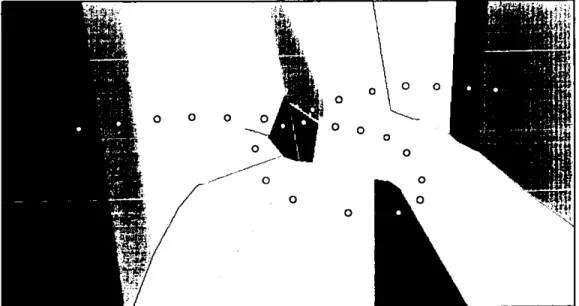
Figure 3-8 Voronoi diagram. The points are represented in white, and the polygons in different colours.
The Voronoi diagram of a set of points P is a set of polygonal areas Q. For each point p1, a polygonal area uIp) is defined such that every point contained in this polygonal area is closer to the point pi than to any other point in P. Figure 3-8 is a Voronoi diagram.
Let P={pi, ... , p}, where 2<—n<, and x1#x1 for i#j, 4i€I,,. The function w(,pj) is the polygonal area associated to the pointpj, and is defined by
I
x-x:5Vx-x forj#i, i,jeJ (9)The Voronoi diagram of P is 12= {0)(pj), ... , LV(prj}.
The Voronoi polygon of a point can be constructed by clipping the area with lines that
bisect, and are perpendicular to, the corresponding lines between this point and its surrounding points.
In mosaic construction a simple procedure to render the mosaic is to copy, from each image, only the pixels which are closer to its centre than to any other image centre. This scheme corresponds to the Voronoi diagram. If each point corresponds to the centre of an image, the Voronoi diagram represents the portions of the images that contribute to the mosaic. The edges of the images can also be derived from the diagram for use in the
blending of the images.
Delaunay triangulation is closely related to the Voronoi diagram. This triangulation is
named after B. Delaunay, who first made use of this dual relationship [Delaunay, 1934].
If the Voronoi diagram is used as a basis, the Delaunay triangulation can be constructed by drawing the lines between the points in adjacent polygons i.e. those which share a common edge. The result is a triangular network. Figure 3-9 shows the Voronoi diagram
of a set of points and the Delaunay triangulation superimposed.
If a mosaic is constructed using the areas of the images indicated by the Voronoi
diagram, then, the points joined by a line in the Delaunay triangulation represent
misalignment or intensity difference exists, it will show at the seams between neighbour images.
The polygonal areas given by the Voronoi diagram are not necessarily covered by the images; the polygons may extend to infinity while the image size is in fact bounded. Note in Figure 3-8 that, disregarding the clipping of the figure boundaries, the polygons on the boundary of the figure are open, i.e. they extend to infinity, because they have no neighbouring points in that direction. In addition, since the images are limited in size, not all connected points in the Delaunay triangulation will represent neighbour images. For instance, in Figure 3-9, images 1, 2, 3 and 4 are neighbours of image 17, however, image
1 is too far from image 17 to overlap. This can be resolved, when constructing the Voronoi polygons, by setting the initial area of each polygon to be equal to the image dimensions before starting the clipping. This is shown in Figure 3-10, where images 1, 2,
and 3 are no longer neighbours of image 17. Figure 3-11 shows a selected image area (in blue) and its neighbour images.
Figure 3-9 Voronoi diagram of a set of points and the Delaunay triangulation superimposed in yellow.
Figure 3-10 Neighbour images from Delaunay triangulation. Note points 1 and 17 are not neighbours since the images they represent do not overlap.
Figure 3-11 The area covered by an image (in blue), and all its neighbour images (in other colours).
3.5 Summary
This chapter has covered the techniques for image registration and image integration used in mosaic construction. It also describes the adverse effects caused by motion parallax, distortions, and moving objects. The next chapter will introduce a problem that originates from the accumulation of small alignment error over a number of images.
Chapter 4 THE LOOPING PATH PROBLEM AND
PROPOSED SOLUTION
4.1 Introduction
In video sequences, successive frames are guaranteed to overlap and, therefore, in mosaicing from video sequences, the registration is computed for successive images. However, a small accumulation of alignment errors occurs when consecutive images are aligned, and in the case of the image path returning to a previous position in the mosaic a significant mismatch between non-consecutive images will result, this is referred to as the Looping Path Problem (LPP) in this thesis. A small alignment error will exist regardless of the image registration method used and the accuracy achieved. The effects of the looping path problem are dramatic when large numbers of images are involved in the loop, and therefore, a large accumulated error occurs (as shown in Figure 4-1).
Figure 4-1 A looping path (in red) exists in this mosaic. The mismatch between different images in the region of the TV set clearly shows the need for consistency between individual alignments.
Figure 4-2 illustrates the problem for the simple case of transformations involving only translations. Assuming a perfect loop has been followed by the camera, images I and 60 should overlap entirely, but misalignment occurs due to accumulation of small errors in each successive image alignment. Therefore, the alignment between images I and 60 in Figure 4.2 is inconsistent with the position of the rest of the images in the mosaic.
misalignment
sweep direction
I
image 20image 50
1
ci image 30Figure 4-2 Misalignment between image I and image 60 due to accumulation of small errors in successive image alignment.
A new method for ensuring the consistency of the positions of all images in the mosaic is proposed in this thesis, resulting in general improvement of mosaic quality and making it possible to create very large field of view mosaics, including full spherical mosaics.
4.2 Previous Approaches
In constructing mosaics from video sequences, almost all existing methods have used parameters computed by successive image alignment. Cumulative alignment errors occur when the position of images in the mosaic is based on successive image alignment only. Good alignment is typically achieved for each individual image alignment, however, cumulative errors cause poor alignment when the image path follows a loop, i.e. when the same area of the scene is covered by images which are distant in the sequence.
Where most of the proposed methods to reduce the LPP are designed for real time mosaic construction (where the mosaic has to be updated continually with every new
incoming image without much reference to distant images in the sequence), these are not adequate for high quality imaging.
This problem has been identified in literature and several solutions proposed. These approaches are discussed in the following sections.
4.2.1 Registering New Image with Current Mosaic
In looking for a solution to the looping path problem it has been proposed that rather than aligning successive images, the alignment can be done instead between an image and the actual mosaic as it is being composited [Burt, Hansen and Anandan, 19961 [Irani, Anandan and Hsu, 1996] [Sawhney and Kumar, 1997]. This solution can be implemented for real-time video mosaicing, that is, when all the images are not available simultaneously, but arrive periodically as a stream of images that need to be integrated into the present mosaic.
This represents an improvement with respect to the successive image alignment method, however, loops involving large numbers of images result in distortions in the mosaic. In some cases, the next image to be aligned with the current mosaic will need to fit two or more different transformations, and distortion will be inevitable. For instance, image 60 in Figure 4-2 will be distorted if an attempt is made to align it simultaneously with image 59 and with image 1.
4.2.2 Registering Sub-mosaics
A similar solution was addressed by Mann and Picard [Mann and Picard, 1995]. They suggested that the sequence of images be split into subsets which are well registered. This produces sub-mosaics which are then globally registered to form the final mosaic. This technique is fast and fairly straightforward to implement, but deciding how to subdivide the image sequence can be problematic, hence a distortion-free mosaic is not ensured.
4.2.3 Distribution of the Error
In constructing panoramic (i.e. cylindrical) mosaics, from a series of images acquired by a panning camera (as shown in Figure 3-5), the looping path problem is reduced to