Performance Analysis of High-speed Optical Packet Switching in High
Performance Computing and Datacentre Networks
Jingyan Wang
B.Eng., M.Sc.A dissertation submitted in fulfilment of the requirements for the award of Doctor of Philosophy (Ph.D.)
School of Electronic Engineering
Faculty of Engineering and Computing
Dublin City University
Supervisors: Prof. Liam P. Barry, Dr. Conor J. McArdle
Declaration
I hereby certify that this material, which I now submit for assessment on the programme of study leading to the award of Doctor of Philosophy is entirely my own work, and that I have exercised reasonable care to ensure that the work is original, and does not to the best of my knowledge breach any law of copyright, and has not been taken from the work of others save and to the extent that such work has been cited and acknowledged within the text of my work.
Signed: ID No.: Date:
Acknowledgements
I would like to thank my supervisor Prof. Liam P. Barry for giving me the opportunity to join his research group and for his expert, sincere and valuable guidance and constant support throughout this PhD. My deepest appreciation and gratitude goes to my co-supervisor Dr. Conor McArdle under whose inspiration and guidance this work has been completed. I sincerely acknowledge his guidance, encouragement, suggestions, understanding and very constructive criticism throughout my research.
My appreciation also extends to my colleagues past and present in the Radio and Optical Commu-nications Laboratory, for the enormous help and support they have provided throughout my time in DCU.
Most of all, I am fully indebted to all my friends and family for their unceasing support and encour-agement. I would like to thank my parents and my sister for their endless love and support. Thank you for always believing in me.
Contents
Acknowledgements i
List of Acronyms vi
List of Tables viii
List of Figures ix
Abstract xv
Introduction 1
1 Networking Technologies and Architectures for HPC and Datacentres 7
1.1 Background . . . 8
1.1.1 Datacentre Traffic Growth . . . 8
1.1.2 Datacentre Traffic Characteristics . . . 9
1.1.3 Requirements for Future Datacentre/HPC Networks . . . 10
1.2 Fundamental Network Theory . . . 11
1.2.1 Crossbar . . . 13
1.2.2 Fat-Tree . . . 14
1.2.3 Clos . . . 15
1.2.4 Spanke . . . 16
1.2.5 Conclusions for Large-Scale Switch Architectures . . . 17
1.3 Electronic Switching in Datacentre Networks . . . 17
1.3.1 Three-tier Datacentre Architecture . . . 18
1.3.2 Leaf-Spine Datacentre Architecture . . . 21
1.3.4 Discussion . . . 23
1.4 Enabling Technologies: Optical Switch Components . . . 23
1.4.1 Micro-Electro-Mechanical System (MEMS) . . . 24
1.4.2 Multiplexer/Demultiplexer (MUX/DEMUX) . . . 25
1.4.3 Coupler/Splitter . . . 26
1.4.4 Semiconductor Optical Amplifier (SOA) . . . 27
1.4.5 Wavelength Converter (WC) . . . 27
1.4.6 Arrayed Waveguide Grating (AWG) . . . 28
1.4.7 Wavelength Selective Switch (WSS) . . . 29
1.5 Optical Switching in Datacentre Networks . . . 30
1.5.1 Optical Circuit Switching Networks . . . 32
1.5.1.1 Hybrid EPS/OCS Datacentre Networks . . . 32
1.5.1.2 Optical Circuit-Switched Datacentre Networks . . . 34
1.5.2 Optical Packet Switching Networks . . . 35
1.5.2.1 Broadcast-and-Select (B&S) OPS Networks . . . 36
1.5.2.2 Wavelength-Routed OPS Networks . . . 38
1.5.2.3 Elastic OPS Networks . . . 40
1.5.2.4 Hybird OCS/OPS Datacentre Networks . . . 41
1.6 Conclusions . . . 43
2 A Novel Energy-Efficient High-Speed Optical Packet Switching Datacentre Network 52 2.1 Introduction . . . 52
2.2 Switch Node Architecture . . . 54
2.2.1 Switch Architecture . . . 54
2.2.2 Label Processing . . . 57
2.2.3 Scheduling Algorithm . . . 58
2.3 Simulation and Numerical Results . . . 60
2.3.1 Simulation Setup . . . 60
2.3.2 Simulation Results and Discussions . . . 65
2.3.2.1 Impact of Input Traffic Process . . . 66
2.3.2.2 FDL Port Interleaving . . . 67
2.3.2.3 FDL Base Delay D . . . 68
2.3.2.5 Dimensioning the FDLs . . . 71
2.3.2.6 Switch Power Consumption . . . 74
2.3.2.7 Scheduling Complexity . . . 76
2.4 Conclusions . . . 79
3 Analytic Modelling and Dimensioning of a Datacentre Optical Packet Switch with Re-circulating Optical Buffers 83 3.1 Introduction . . . 83
3.1.1 Related Work . . . 84
3.1.2 Overview of Modelling Approach . . . 86
3.2 Optical Packet Switch Architecture . . . 87
3.3 The Analytical Queueing Model . . . 89
3.3.1 Preliminaries . . . 91
3.3.1.1 Markov-modulated Poisson Process (MMPP) . . . 91
3.3.1.2 Interrupted Poisson Process (IPP) . . . 94
3.3.2 The Switch Queueing System . . . 95
3.3.3 The Optical Buffer Queueing System . . . 98
3.4 Performance Analysis . . . 101
3.4.1 Poisson Arrival Traffic . . . 102
3.4.1.1 Approximations of the Contention Probability . . . 102
3.4.1.2 Approximations of Packet Latency . . . 105
3.4.2 Interrupted Poisson Arrivals (IPP) . . . 107
3.5 Network Dimensioning . . . 109
3.5.1 Problem Formulation . . . 109
3.5.2 Optimisation Algorithm . . . 110
3.5.3 Optimal Solutions . . . 111
3.6 Conclusion . . . 114
4 Flexible Optical Packet Switching for HPC and Datacentres 118 4.1 Introduction . . . 118
4.2 OPS Architecture . . . 120
4.3 Hot-spot Traffic Model . . . 122
4.4 Elastic Wavelength Allocation . . . 124
4.4.2 Stage II: FDL Traffic Assignment . . . 126
4.5 Performance Evaluation . . . 129
4.5.1 Simulation Setup . . . 129
4.5.2 Results and Discussions . . . 132
4.5.3 Power Consumption Minimisation . . . 135
4.5.4 Hybrid Buffering . . . 136
4.6 Conclusion . . . 137
5 Large-scale Optical Packet Switching Datacentre Networks Using Combined Optical Buffering and Packet Retransmission 139 5.1 Introduction . . . 139
5.2 Network Architecture . . . 141
5.2.1 Overview of Contention Resolution Methods . . . 144
5.3 Flexible Network Load Scheduling Algorithm . . . 145
5.4 Retransmission Mechanism . . . 148
5.5 System Performance Evaluation . . . 151
5.5.1 Simulation Setup . . . 151
5.5.1.1 General Parameter Settings . . . 151
5.5.1.2 Performance Measurements . . . 153
5.5.1.3 Traffic Patterns . . . 153
5.5.2 Flexible Network Load Scheduling Analysis . . . 155
5.5.3 Contention Control Analysis . . . 159
5.5.3.1 Recirculating Optical Buffering Analysis . . . 159
5.5.3.2 Packet Retransmission Analysis (without FDLs) . . . 161
5.5.3.3 Hybrid Recirculating FDL/Retransmission Analysis . . . 167
5.6 Impact of Geographical Distance on Network Performance . . . 172
5.7 Conclusions . . . 174
6 Conclusion and Future Work 177 6.1 Conclusion . . . 177
6.2 Future Work . . . 180
List of Acronyms
AWG Arrayed Waveguide Grating B&S Broadcast-and-Select
CAGR Compound Annual Growth Rate
CWDM Coarse Wavelength Division Multiplexing DEMUX Demultiplexer
DWDM Dense Wavelength Division Multiplexing E/O Electro-Optic
FDL Fibre Delay Line
FWC Fixed Wavelength Converter HPC High Performance Computing
IID Independent and Identically Distributed IPP Interrupted Poisson Process
LAUC-VF Latest Available Unused Channel with Void Filling MEMS Micro-Electro-Mechanical System
MMPP Markov-modulated Poisson Process MUX Multiplexer
NAK Negative Acknowledgement O/E Optic-Electro
O/E/O Optical-Electrical-Optical OCS Optical Circuit Switching OLE Optical Label Extractor OPS Optical Packet Switching OXC Optical Cross-Connect PreRes Pre-Reservation
QoS Quality-of-Service RAM Random Access Memory RTT Round-Trip Time
SOA Semiconductor Optical Amplifier ToR Top-of-Rack
TWC Tunable Wavelength Converter WC Wavelength Converter
WDM Wavelength Division Multiplexing WS Wavelength Selector
List of Tables
1.1 Comparison of some fundamental network structures.N denotes the switch size. . 12
2.1 Table of Notation . . . 64
2.2 The power consumption comparison between different buffers. . . 76
3.1 Table of Notation . . . 96
3.2 A collection of conditions for the optimisation . . . 111
3.3 Optimal solutions forN= 64.Emin(K, S, L)represents the minimum power con-sumption (W). Emin(K, S, L) represents the minimum power consumption per switch port, defined byE(K, S, L)=E(K,S,LN ) . . . 112
3.4 Optimal solutions for N= 256. Emin(K, S, L) represents the minimum power consumption (W).Emin(K, S, L)represents the minimum power consumption per switch port, defined byE(K, S, L)=E(K,S,LN ) . . . 113
3.5 Power consumption comparison. The worst-case solutions are obtained by explor-ing the feasible state space for the maximum, and the best-case solutions are the global optimal solutions in Tables 3.3 - 3.4 . . . 113
4.1 Table of Notation . . . 131
4.2 Power consumption for a target packet loss rate of10−6 . . . 136
4.3 Blocking probability versus electronic buffer sizeP (P input/output ports) . . . 136
5.1 Table of Notation . . . 152
List of Figures
1.1 Current trends and future projections of overall datacentre traffic. Global datacentre traffic is estimated to grow at a Compound Annual Growth Rate (CAGR) of22%,
and intra-datacentre traffic will grow at a21%CAGR. . . 8
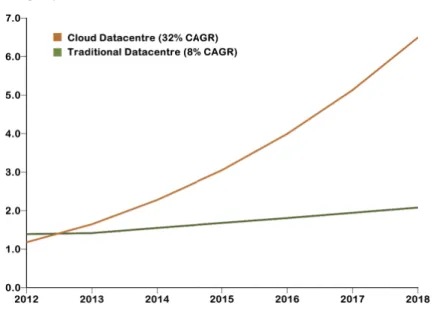
1.2 Cloud datacentre traffic is predicted to grow with a CAGR of32%. . . 9
1.3 AN ×N Crossbar switch . . . 13
1.4 Tree-based structures . . . 14
1.5 Three-stage Clos . . . 15
1.6 Spanke architecture . . . 16
1.7 Three-tier datacentre network . . . 19
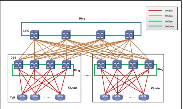
1.8 Current Facebook Datacentre Network. ToR: Top-of-Rack Switch. CES: Cluster Electronic Switch. CSW: Core Switch. . . 20
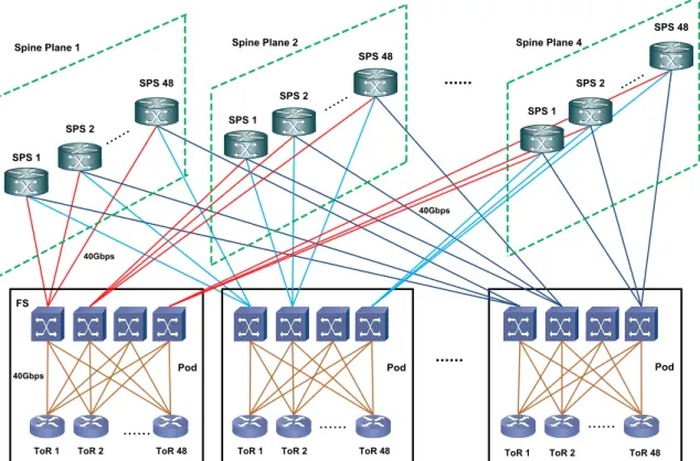
1.9 Next-generation Facebook Datacentre Network. ToR: Top-of-Rack Switch. FS: Fabric Switch. SPS: Spine Switch. . . 21
1.10 A leaf-spine network. . . 22
1.11 A three-dimensional optical Micro-Electro-Mechanical System (MEMS) switch. . 24
1.12 MUX/DEMUX . . . 25
1.13 AN ×M optical coupler. . . 26
1.14 A1×N optical splitter. . . 26
1.15 A Semiconductor Optical Amplifier (SOA). . . 27
1.16 The cyclic wavelength routing pattern of a6×6Arrayed Waveguide Grating (AWG) switch. . . 28
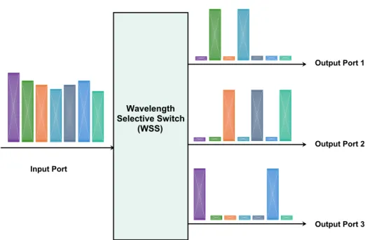
1.17 The switching functionality of a1×3 Wavelength Selective Switch (WSS). The input port receives an optical signal containing7wavelength channels . . . 30
1.18 Hybrid c-Through network . . . 32
1.20 Hybrid SSX architecture. . . 33
1.21 Optical circuit-switched OSA architecture. . . 34
1.22 Optical packet-switched STIA architecture. . . 36
1.23 Optical packet-switched Spanke-type architecture. . . 37
1.24 Optical packet-switched Petabit architecture. . . 38
1.25 AWG-based LIONS architecture. . . 39
1.26 Hybrid OCS/OPS LIGHTNESS architecture [70, 71]. . . 42
1.27 The space wavelength-routed optical cross-connect (OXC). . . 43
2.1 Proposed hybrid bufferN ×N AWG-based packet switch architecture . . . 54
2.2 Waveband partitioning. The WDM signal at an AWG output port consists of (N+L) wavelengths, each coming from an AWG input. The optical DEMUX divides the WDM signal into K continuous wavebands, each of which contains X=(N + L)/Kwavelengths. . . 55
2.3 Waveband assignment of a 8×8 AWG switch with 2 FDLs. That is, N=8 and L=2. K andSare set to beK=2andS=3. (a) OPS with spread FDLs. (b) OPS with non-spread FDLs. . . 56
2.4 The Ethernet-based optical packet format . . . 57
2.5 Label separation and processing . . . 58
2.6 Scheduling/reservation procedure . . . 59
2.7 Simulation setup for anN×N optical packet switching network . . . 61
2.8 Simulation models of the ToR switch and the core OPS switch . . . 62
2.9 Contention performance of the bufferless switch. . . 66
2.10 Packet drop ratioPlossversus input load for two values ofKunder four different in-put traffic processes: (1) Poisson traffic with exponential packet length, (2) Poisson traffic with constant packet length, (3) IPP traffic with exponential packet length, and (4) IPP traffic with constant packet length. . . 67
2.11 Performance comparison between spread and non-spread FDL schemes as a func-tion of the offered load for scenarios with fixed parameter values of K = 6 and D= 0.1T. . . 68
2.12 Performance measurements of AWG switch with hybrid buffer as a function of FDL base delayDfor three values ofN. ParameterK is 6, and input loadρis80%of maximum load. The ‘No FDLs’ point, when D = 0, means that only electronic buffer is employed for buffering. . . 69 2.13 System delay versus offered load for three different configurations of switch sizeN
and FDL sizeLandS, with two values ofK and base delay parameterDin each configuration. . . 70 2.14 Appropriate values ofPfor different numbers of FDLsL, for different switch sizes
N. The value ofP for a givenLcorresponds to the maximum number of simulta-neously busy electronic buffer outputs at80%load,K= 6,D= 0.1T. . . 71 2.15 Average packet delays versus FDL sizeL. P is set for each different value of L
according to Figure 2.14. The dashed straight lines represent the results for switch architecture with only electronic buffer. . . 73 2.16 The percentage (%) of contention traffic carried by two different buffers. Parameters
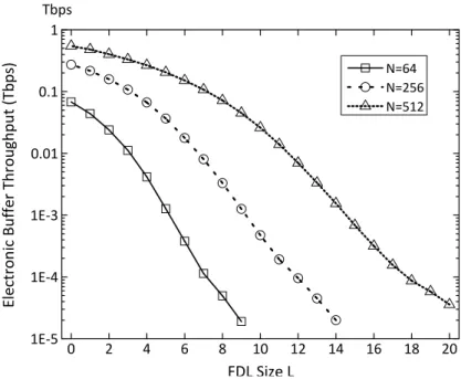
K = 6,D = 0.1T,ρ = 80%. P is set for each different value ofLaccording to Figure 2.14. . . 73 2.17 The electronic buffer throughput versus FDL sizeLin three switch configurations:
(1) N = 64, (2)N = 256, and (3)N = 512. ParametersK = 6, D = 0.1T,
ρ= 80%. . . 74 2.18 The power efficiency is estimated as a function of parameter Lin three different
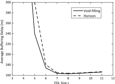
scenarios : (a)N = 64, S = 6(b)N = 256, S = 10(c)N = 512, S = 10. . . 75 2.19 The packet header blocking probability due to late scheduling versus computation
time limit. In hybrid buffer scenarios, the worst-case computation time for LAUC-VF algorithm is around 2.4µs and the computation time for horizon algorithm is 1.8µs. The maximum computation time for electronic-buffer only scenario is1.5µs 77 2.20 The average latency versus FDL sizeLwhenP is fixed as12. . . 78 2.21 The electronic buffer throughput versus FDL sizeLwhenPis fixed as12. . . 78 3.1 An overview of the analytical queueing model. . . 86 3.2 The AWG-based optical packet switch with optical FDL buffers, providing high
3.3 The analytical model of the proposed optical switch. The switch queueing model consists ofN ×K independent and identical MMPP/M/1queues. The arrival pro-cess to the MMPP/M/1 queue is composed of a primary MMPP (Q0,Λ0), andR
independent recirculating traffic flows (Qi,Λi),i = 1, . . . , R. The optical buffer queueing model is composed ofSindependent and identical MMPP-based queue-ing models with the MMPP arrival process which includesR independent traffic flows. . . 90 3.4 The buffer queueing model consists ofS parallel Markov-modulated finite-server
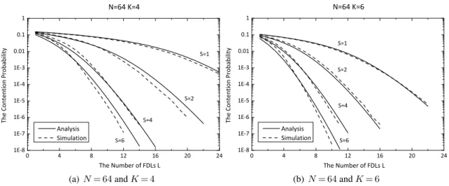
queues. Two different representations are developed to characterise the Markov-modulated finite-server queue: (a) a single MMPP/M/Lmodel and (b) a cascaded model ofLMMPP/M/1queues. . . 100 3.5 N= 64,ρ= 0.8, R= 3andDG= 0.1. The observations are obtained for two
dif-ferent scenarios:K= 4andK= 6. . . 103 3.6 N= 256, ρ= 0.8, R= 3 and DG= 0.1. The observations are obtained for two
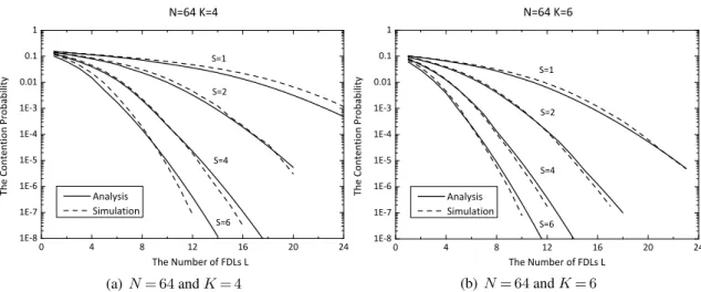
different scenarios: K= 4andK= 6. . . 103 3.7 N= 64,ρ= 0.8,R= 3andDG= 1. The observations are obtained for two different
scenarios: K= 4andK= 6. . . 104 3.8 N= 256,ρ= 0.8,R= 3andDG= 1. The observations are obtained for two
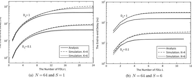
differ-ent scenarios:K= 4andK= 6. . . 104 3.9 N= 64,ρ= 0.8andR= 3. The overall system delays are plotted versus the number
of FDLsLfor different values of parameterDG:DG= 0.1andDG= 1 . . . 106 3.10 N= 256,ρ= 0.8andR= 3. The overall system delays are plotted versus the
num-ber of FDLsLfor different values of parameterDG:DG= 0.1andDG= 1 . . . . 106 3.11 The blocking probability is plotted versus FDL unit delayDGin two different
sce-narios: (i)N= 64,K= 6,S= 2andL= 13and (ii)N= 256,K= 4,S= 10and
L= 16. . . 107 3.12 The overall delay is plotted versus FDL unit delayDGin two different scenarios:
(i)N= 64,K= 6,S= 2andL= 13and (ii)N= 256,K= 4,S= 10andL= 16. 107 3.13 The contention probability is plotted versus the link load for different input IPP
traffics. . . 108 3.14 The overall delay is plotted versus the link load for different input IPP traffics. . . . 108
3.15 N= 64. The feasible state space ofS andL in the scenarios: K= 4andK= 6. Note that the blank space represents the area in which the state point breaks the
constraints. . . 112
3.16 N= 256. The feasible state space ofS andLin the scenarios: K= 4andK= 6. Note that the blank space represents the area in which the state point breaks the constraints. . . 112
4.1 Architecture of proposed flexible-bandwidth datacentre optical packet switch. . . . 120
4.2 An example network architecture (Clos Network) using multiple identical optical switches to build out a large datacentre network. . . 121
4.3 Heatmap of128×128hotspot traffic matrix, generated using the random circulant block-matrix scheme. The matrix has full load (M = 1), with individual source-destination loads ranging between0%and30%. . . 125
4.4 Simulation setup of the flexible optical network. . . 130
4.5 Packet loss rates in switch with fixed Wavelength Allocation (WA) scheme under uniform and non-uniform (hotspot) traffic, for varying switch dimensions: number of FDLsL, number of transmission channels (FWCs) per output portK, number of TWCs per FDLS. . . 132
4.6 Comparison of packet loss rates for fixed and flexible allocation schemes under hotspot traffic load. . . 133
4.7 The packet loss difference between fixed resource allocation and flexible resource allocation, P b=Pfixed−Pflexible, for each source-destination traffic stream in the scenarioK= 4,S= 4,L= 12 . . . 134
4.8 The packet loss difference between fixed resource allocation and flexible resource allocation, per input port. . . 135
5.1 The proposed modular optical packet-switched datacentre network (DCN). . . 141
5.2 The proposed AWG-based optical packet switching network. . . 142
5.3 The flexible network scheduling algorithm. . . 147
5.4 Random Retransmission (RR) . . . 149
5.5 Pre-Reservation Retransmission (PRR) . . . 150
5.6 The relationship between the original traffic load and the capped traffic load in hot-spot traffic pattern. . . 155
5.7 Performance evaluation of the flexible resource scheduling under uniform traffic
pattern. . . 156
5.8 Performance evaluation of the flexible resource scheduling under hot-spot traffic pattern. . . 156
5.9 Performance evaluation for the fixed scheduling under hot-spot traffic pattern. . . . 158
5.10 All-to-all communication pattern . . . 160
5.11 Hot-spot traffic pattern . . . 160
5.12 Network workload and packet retransmission rate under uniform traffic pattern. . . 162
5.13 Network throughput and buffer size requirement under uniform traffic pattern. . . . 163
5.14 (a) resulting network workload, (b) packet retransmission rate, (c) network through-put and (d) buffer size requirement are plotted as a function of the offered network loadρunder non-uniform traffic pattern. . . 165
5.15 Network performance versus offered network loadρunder uniform traffic pattern. 166 5.16 Network performance versus offered network loadρunder hot-spot traffic pattern. 166 5.17 Network performance of the combined contention control scheme withR= 1under uniform traffic pattern. . . 169
5.18 Network performance of the combined contention control scheme withR= 2under uniform traffic pattern. . . 169
5.19 Packet retransmission rate in the combined recirculating FDL/retransmission scheme under uniform traffic pattern. . . 170
5.20 Network performance of the combined contention control scheme under hot-spot traffic pattern. Note thatR= 1. . . 171
5.21 Network performance of the combined contention control scheme under hot-spot traffic pattern. Note thatR= 2. . . 171
5.22 Packet retransmission rate in the combined contention control scheme under non-uniform traffic pattern. . . 172
5.23 Contention performance . . . 173
5.24 Requirement for buffer size . . . 173
Performance Analysis of High-speed Optical Packet Switching in High
Performance Computing and Datacentre Networks
Jingyan Wang
Abstract
The massive growth in datacentre traffic, due to a huge increase in the deployment of data-intensive applications, is forcing datacentre infrastructure to migrate away from conventional electronic packet-switched networks, where capacity scaling imposes significant financial and technical con-straints, and to evolve towards more advanced architectures. Motivated by this, new optical switch-ing technologies and networkswitch-ing architectures, capable of providswitch-ing very large bandwidth capacity, high scalability, high switching speed and high energy efficiency, are being targeted for building next-generation high-performance datacentre and High Performance Computing (HPC) networks. Optical packet switching technology is considered to be a long-term solution to meet these design challenges, as it can exploit fully the enormous potential capacity enabled by optics and support high switching flexibility at packet level.
In this thesis, new wavelength-routed optical packet switching architectures, which exploit the func-tionalities of key optical switching components such as Tunable Wavelength Converters (TWCs), Arrayed Waveguide Gratings (AWGs) and Wavelength Selective Switches (WSSs), to realise all-optical switching, are proposed for use as next-generation datacentre and HPC networks. To max-imise the efficiency of the proposed optical switching architecture, a dynamic bandwidth provision-ing algorithm, which allocates switch resources to traffic demands based on application require-ments, is developed to further enhance network flexibility, resource utilisation and network per-formance. Moreover, based on the proposed switch architectures, a large-scale high-performance datacentre network with flexible central control is modelled, with a view of determining the opti-mal network topology and traffic scheduling methods. This flexible network architecture employs a modular design and combines transparent optical packet switches, based on Arrayed Waveguide Grating (AWG) routers, and a hybrid congestion control scheme using recirculating Fibre Delay Lines (FDLs) along with novel packet retransmission schemes. The work carried out in this thesis indicates that the proposed network structure not only provides high scalability, capable of hosting hundreds of thousands of severs, but also delivers high bandwidth utilisation and network provision-ing flexibility. The network offers a promisprovision-ing and viable networkprovision-ing solution to address current and future application needs in datacentre and HPC environments.
Introduction
Cloud computing applications and data-intensive Internet services are motivating the installation of warehouse-scale datacentres - huge facilities with hundreds of thousands of servers that are re-quired to exchange very large volumes of data at high speeds and low latencies. Coinciding with the explosion of data traffic volumes exchanged between servers within datacentres is an escalation of the required communication capacity which presents significant technological challenges for the datacentre networking infrastructure. Current network architectures follow a three-tier structure comprising access (L1), aggregation (L2) and core (L3) layers. The basic network elements are switches and routers which process data streams electronically and then convert them to optical form for Wavelength Division Multiplexing (WDM) transmission on high-capacity point-to-point optical links between the switches and routers. A problem associated with this type of architec-ture is the capacity scaling issue, stemming from the multi-layer naarchitec-ture of the network topology. More precisely, the aggregated traffic demands at higher levels of the system hierarchy potentially require progressively larger bandwidth capacities, and consequently put the statically-provisioned and oversubscribed upper tiers under strain. Additionally, as datacentres continue to expand, the traffic demands will increase massively. To keep up with this rapid growth, the electronic switches and routers need to scale with regard to data rates, connectivity and bandwidth capacity, which is technically challenging and requires excessive amounts of power. Further, the installation of the re-quired Optical-Electrical-Optical (O/E/O) converters for WDM transmission dramatically increases the investment in equipment and equipment power consumption. These drawbacks are stressing the existing datacentre networks and motivating the network to evolve towards advanced all-optical switching and routing.
Optical switching is a strong candidate for building next-generation large-scale networks, as it al-lows the exploitation of the unprecedented potential provided by WDM technology in terms of super-high bandwidth, fast switching speed, low latency, wavelength-based switching/routing, data
rate/format transparency and low power consumption per bit transmitted. Depending on the switch-ing granularity, optically switched solutions can be classified into two categories: Optical Cir-cuit Switching (OCS) and Optical Packet Switching (OPS). OCS is usually built based on Micro-Electro-Mechanical System (MEMS), which promises high bandwidth capacity, high switch port count and low power consumption. However, a MEMS-based OCS exhibits switching speeds in the order of milliseconds and is therefore unable to handle fast changing bursty traffic in high performance computing and datacentre environments. Alternatively, OCS can be used to setup semi-permanent dedicated lightpaths between the source and destination, maintained for the en-tire transmission session, which ensures the data traffic traverses the network in optical format with guaranteed bandwidth. A drawback with this technique is the underutilisation of the available band-width on average, as the established paths cannot be used for other communications even when their links are idle. These restrictions of OCS with respect to switching speed and bandwidth utilisation make it challenging to fulfill the performance requirements of the applications, especially when the amount of data traffic involved is so massive and with unpredictable and dynamic traffic patterns. For that reason, a flexible switching paradigm, which supports all-optical switching at packet gran-ularity, is preferable, and this can be provided by OPS. Optical packet switching has the potential of delivering on-demand bandwidth and fine-grained granularity with fast switching speed, making it a suitable substitution for large electronic packet switches and a solution for future interconnection networks.
Optical packet switch design is currently being greatly facilitated by the increased availability of a diverse range of active and passive optical components, including the optical Multiplexer (MUX) and Demultiplexer (DEMUX), the Tunable Wavelength Converter (TWC), the Wavelength Selec-tive Switch (WSS) and the Arrayed Waveguide Grating (AWG) which is a low-loss passive optical switching device where the reconfiguration is performed by tuning the input signal on the appropri-ate wavelength using fast TWCs. Progress in advanced optical components and switching technolo-gies offers the possibility of constructing a high-speed, high-bandwidth and energy-efficient optical packet switch (OPS), with simple routing control, suitable for interconnecting many servers.
Despite these advantages, the issue of packet contention resolution in OPS is problematic, due to the lack of viable optical Random Access Memory (RAM). As such, congestion management sig-nificantly impacts application performance, and eventually determines the future role of OPS in High Performance Computing (HPC) and datacentre networks, thus the research and development of contention avoidance solutions are extremely important. In response to this, optical buffers
emu-lated with Fibre Delay Lines (FDLs) have been proposed to delay the contending packets for a fixed time, depending on fibre length. Other techniques to address the need for packet buffering include adding electronic buffers, deflection routing schemes and wavelength conversions. Alternatively, data recovery mechanisms have also been exploited to eliminate the traffic loss in optical network. Further, additional packet scheduling/routing flexibility in the network could be a tremendous ben-efit, where network capacities are dynamically allocated to meet the dynamically changing traffic patterns, thus alleviating packet contention conditions. Moreover, hybrid network design (optical and electronic switching) is another effective approach, as it exploits the advantages of different switch paradigms and improves the overall effectiveness of the network, which in turn reduces the required buffering capacity. This thesis focuses on the development of scalable, high-performance OPS networks for datacentres and HPC with efficient contention solutions.
Main Thesis Contributions
The main contributions of this thesis are:
• A novel high-port-count optical packet-switched architecture, where AWG and TWCs are employed to support high-speed switching, is developed for HPC and datacentres. To resolve packet contention, the network is configured with share-per-node optical buffers. Exten-sive simulations are performed to analyse the impact of various FDL parameters on network performance. With proper dimensioning of optical buffers, significant performance improve-ments are obtained. In addition, to realise a non-blocking switching scheme, the inclusion of small-scale electronic buffering functionality is investigated, with the aim of minimising the number of the switch components required. A follow-up investigation on power consumption and packet scheduling computation complexity further confirms the feasibility of the AWG switch in large-scale networks.
• Simulation-based dimensioning turns out to be complex and computationally-intensive, thus it is essential to provide an analytical performance model, which accurately captures the be-haviours of the presented AWG switch with optical buffers and accelerates performance eval-uation studies. A mathematical queuing model is developed, which allows a detailed analysis of the overall performance against various network design parameters. Complemented with a heuristic procedure, the model is extended to resolve the dimensioning problem which is formulated as a constrained optimisation problem with the objective of allocating the
appro-priate network parameter configuration which potentially achieves the most power savings, simultaneously meeting network performance constraints in terms of packet loss probability and overall latency.
• An enhanced optical packet switch design, based on combining AWG and WSSs, is devel-oped, which allows more flexible and dynamic end-to-end bandwidth re-provisioning. The prominent attribute of the WSS is the elastic switching granularity, which enables the dy-namic allocation of capacity to traffic demands. This flexibility enhances the overall resource utilisation as well as the network’s ability to adapt to changing communication patterns. The system performance is examined under realistic non-uniform traffic, and compared with that of a static bandwidth allocation strategy. The performance improvements suggest that the proposed scheme is an effective solution for more efficiently provisioning applications in HPC and datacentres.
• A scalable datacentre interconnection network of combined optical and electronic packet switches is proposed, together with a centralised dynamic reconfiguration algorithm. The network possesses a number of advantages. First, the network platform is highly scalable, and capable of interconnecting a large number of servers, due to the layered topology. Ad-ditionally, the dynamically reconfigurable OPS is implemented in conjunction with mature electronic switching technology, making possible the exploitation of the benefits of high-capacity optical switching and fine-grained electronic switching. Furthermore, the flexible global routing scheme, which supports dynamic network reconfigurations, significantly en-hances the overall performance. Another important benefit is the resolution of traffic loss, which is accomplished through the deployment of a combined contention control scheme employing recirculating optical buffering (FDLs) and a novel packet retransmission mecha-nism.
Thesis Structure
The remainder of this thesis is structured as follows:
• Chapter 1 reports the forecasted growth of datacentre traffic and expected datacentre traffic characteristics, along with the networking requirements for datacentres arising from these trends. Fundamental networking structures and key enabling technologies used for building large-scale datacentre interconnection networks are discussed. The remainder of this chapter
provides an overview of recent developments in switching technologies, operation strategies and architectural designs for HPC and datacentre networks. Several recently proposed net-working technologies and proposals are reviewed in detail. The benefits and design issues of these proposals are also discussed.
• Chapter 2 proposes a novel high-port count, high-speed optical packet switch which employs an Arrayed Waveguide Grating (AWG) component for cross-connection, a hybrid optical/ electronic buffering scheme and a method for efficiently integrating Fibre Delay Line (FDL) buffer capacity into the AWG switch. A detailed description of the simulation model of the proposed optical network is presented in this chapter. Extensive simulations have been carried out to investigate the impacts of various network parameters on network performance and power consumption. The overall goal is to resolve the network dimensioning problem where the objective is to optimally dimension the optical and electronic buffer resources in an energy-efficient manner. Further, the computational complexity of the scheduling algorithm in the hybrid-buffered switch is investigated.
• Chapter 3 is devoted to developing a Markov-modulated mathematical model for the pro-posed optical packet switch with recirculating Fibre Delay Line buffers. The analytical framework numerically models the behaviours of the optical switch, and allows a detailed performance analysis regarding contention probability and communication latency. The cor-rectness and accuracy of the proposed analytical model is confirmed by the comparison with the simulation results under both smooth and bursty traffic types. Further, on the basis of the developed analytical model, the dimensioning of the switch’s component parts is resolved as an optimisation problem with the objective of addressing the performance requirements and minimising the deployment and power costs. A heuristic optimisation algorithm is imple-mented to resolve the constrained optimisation problem.
• Chapter 4 introduces a flexible optical packet-switched architecture for HPC systems and datacentre networks using passive optical components of the AWG and Wavelength Selec-tive Switches (WSSs). A novel aspect of the architecture is the use of a flexible resource allocation algorithm, which is developed in this chapter. To facilitate the flexible wavelength assignment in FDLs, an analytical model of the optical switch which accurately approximates the overflow traffic loads from optical switch to FDL buffers, is developed. A non-uniform, realistic traffic model is presented, and the network performance and energy consumption of the flexible optical network is investigated under both uniform and non-uniform traffic
patterns. The network dimensioning problem is also resolved with the aim of satisfying the performance constraints and minimising the power consumption.
• Chapter 5 introduces the network architecture of the proposed large-scale hybrid electron-ic/optical datacentre interconnection network, followed by a detailed description of the dy-namic global traffic scheduling procedure. Further, a novel congestion control method, com-bining the recirculating optical buffers and the packet retransmission mechanism, is intro-duced. Through extensive simulations, the system performance of the proposed datacentre network is evaluated under both all-to-all traffic and a more realistic non-uniform datacentre workload, highlighting its benefits regarding network throughput, scalability and flexibility.
• Chapter 6 presents the concluding remarks of the thesis and proposes some potential future research topics related to the subject.
Chapter 1
Networking Technologies and
Architectures for HPC and
Datacentres
A datacentre is a massive warehouse-scale computer system with hundreds or thousands of servers [1]. The datacentres support a high-level computational capacity for running big data and information-intensive applications efficiently, quickly and reliably. High Performance Comput-ing (HPC) is similar to datacentres, the difference beComput-ing that HPC incorporates massively parallel processing such that the processors can work together to resolve an enormously complex compu-tational problem. In both datacentres and HPC systems, it is of crucial importance to design an efficient interconnection network which supports high-speed interactions between servers. Various interconnects for datacentres and HPC systems have been proposed and prototyped in recent years, such as electronic networks, hybrid electronic/optical systems and all-optical schemes. This chapter provides a qualitative categorisation and comparison of some newly proposed networking technolo-gies and designs for HPC and intra-datacentre networks. Fundamental networking structures and key enabling technologies used for building these interconnection networks are also reported. As motivation and background, the forecasted growth of datacentre traffic and expected datacentre traf-fic characteristics are first reviewed and the technological challenges arising from these trends are discussed.
1.1
Background
1.1.1 Datacentre Traffic Growth
The network platforms in HPC and datacentres are constantly scaling and evolving to sustain the un-precedented growth in application data traffic. Figure 1.1 illustrates the forecasted growth of global datacentre traffic, based on recent statistics from Cisco [2, 3]. The annual global datacentre traffic is projected to grow more than threefold, from2.6zettabytes 1in 2012 to8.6zettabytes by 2018, with a22percent Compound Annual Growth Rate (CAGR). It is estimated that the forecasted traffic volume of8.6zettabytes in 2018 is equivalent to the amount of traffic generated by three hours of high-defination (HD) video streaming for the entire population (7.6billion people) [4].
Figure 1.1: Current trends and future projections of overall datacentre traffic. Global datacentre traffic is estimated to grow at a CAGR of 22%, and intra-datacentre traffic will grow at a 21% CAGR.
Apparently, the main contributor to this growth is the traffic exchanged within datacentres, making up roughly75percent of the overall datacentre traffic for the period 2012-2018. By 2018, the intra-datacentre traffic is expected to reach6.4zettabytes annually from2.0 zettabytes in 2012, which amounts to a CAGR of 21%. This explosive growth is largely due to the deployment of cloud technology, as illustrated by Figure 1.2, which depicts the predicated growth of cloud datacentre traffic [2, 3]. Cloud datacentre traffic is growing rapidly at a CAGR of∼32%, expected to reach
1
A zettabyte is1021
Figure 1.2: Cloud datacentre traffic is predicted to grow with a CAGR of32%.
6.5zettabytes by the end of 2018. Approximately76percent of data centre traffic will come from cloud computing applications by 2018, up significantly from46percent in 2012, thus cloud traffic is dominating the datacentre [4]. This continuing trend is changing the nature of datacentre traffic, as discussed in the next section.
1.1.2 Datacentre Traffic Characteristics
Intra-datacentre traffic is growing rapidly, mainly as a consequence of hosting a variety of cloud applications and services. This ever-increasing trend highlights the fact that the design of a highly reconfigurable network infrastructure which efficiently supports the heterogeneous traffic profiles of a wide range of applications, is of particular importance. Analysing the traffic characteristics facilitates the design of switch technology, network structure and resource management protocols. For that reason, significant research efforts [5–11] have been undertaken to explore the behaviours of datacentre applications. Even through the traffic demands evolve rapidly and constantly in the datacentre environment, and it is challenging to accurately model the communication patterns, these studies manage to statistically characterise various aspects of datacentre applications.
According to [6, 7], datacentre traffic is non-uniform and exhibits rack locality. More specifically, the majority of traffic generated by a rack, up to80%, stays inside the rack, and only a small portion of traffic, referred to as inter-rack communication, traverses across the network. Analysis in [5, 7–9] suggests that there exists a number of hot-spots in network traffic, and as such the communication
matrix is extremely sparse and skewed, because an individual host tends to communicate with a small subset of remote racks at any time [5]. Further, [10] reveals that the traffic pattern exhibits low concurrency, that is, a server generates a relatively small number of concurrent connections compared to the network-wide scale. These findings provide important guidances for the design of datacentre networks.
Traffic characterisation is a crucial part of datacentre networking, as the dynamics in traffic patterns have significant impacts on service quality of datacentre applications. However, most recently pro-posed datacentre architectures are designed for the worst-cast uniform traffic pattern where traffic demands are uniformly distributed across all servers. As a consequence, these networks can exhibit low flexibility, low resource utilisation, and are unable to support high-demand hot-spot traffic pat-terns and adapt to changing traffic demands. Therefore, when designing a datacentre interconnec-tion network, it is of importance to consider traffic variainterconnec-tions and evaluate the network architecture under various types of communication patterns so as to ensure the robustness and reliability of the network architecture to future traffic trends in datacentres.
1.1.3 Requirements for Future Datacentre/HPC Networks
The continuing growth of datacentre traffic, coupled with its dynamic nature, imposes significant technical and operational challenges on current datacentre networks. To address these challenges, the network infrastructure will need to evolve towards more advanced network architectures, which provide larger bandwidth capacity, more network flexibility and faster communication speed, so as to adapt to new dynamic, data-intensive cloud-driven applications. Although much effort has been devoted to designing innovative electronic-switched interconnection networks, these architectures are based on electronic switching and routing, and will ultimately be constrained with respect to bandwidth capacity, network connectivity and power consumption. This has led to the emergence of optical switching technology in datacentres which exploits the ultra-high bandwidth capacity offered by optical fibres. Due to its high data-rate transmission, optical transparency, high capacity and flexibility and low energy consumption, optical switching technology has been considered as a long-term solution to meet the tremendous capacity needs highlighted in Section 1.1.1. Several different high-performance datacentre architectures, deploying photonic technologies have been developed in the research literature. These pioneering proposals have successfully demonstrated the enormous potential of optical switching technology in resolving the application needs in large-scale datacentres.
Apart from switching technologies, various switch topologies have been proposed for use in build-ing large-scale networks. These fundamental network structures remain mostly the same, despite the evolution in the networking technologies used to implement the topologies. The next section explores the fundamental switching topology principles which are commonly used in datacentre networking.
1.2
Fundamental Network Theory
In datacentre and HPC networks, a large-scale network is required to interconnect hundreds of thousands of servers. Such a network can be constructed using a single-stage crossconnect with very high port count or a multi-stage network architecture consisting of multiple levels of smaller switch fabrics. The single-stage cross-connect provides direct connections between any input/output, but the device fabrication of a hundred-thousand port-count switch is technologically challenging and economically not feasible. An effective solution to this problem is through multi-stage switching which makes use of low-radix switch elements to build very large scalable cross-connects. The fundamental structures of multi-stage network designs include Crossbar, Fat-Tree, Clos and Spanke topologies. A multi-stage architecture is mainly characterised by three aspects: the number of basic switch modules required, the non-blocking pattern and the loss uniformity.
Number of Switch Modules: In a multi-stage architecture, the large-scale switch fabric is con-structed by interconnecting several basic switching blocks in a multi-stage topology. The number of switch modules needed hinges on the implementation details of the network structure. This property has a significant impact on deployment costs, blocking characteristics and network control complexity, as discussed later.
Non-blocking Pattern: The blocking characteristic is an important factor in the design of large-scale switching networks. A switch fabric is either blocking, in which case some input/output connections cannot be realised [12], ornonblocking, in which case any input/output configuration is possible at any time. For most services and applications, nonblocking switch network is de-manded in order to ensure communication quality. There are three types of non-blocking pattern: rearrangeable nonblocking, wide-sense nonblocking and strict-sense nonblocking.
• Rearrangeable nonblocking. A rearrangeable nonblocking switch architecture is able to in-terconnect any idle input/output pair by allowing the existing active connections to be inter-rupted. Although it ensures the nonblocking property, the connections in progress may be
disturbed. Problems of this type can significantly impair the application performance. Fur-thermore, a high level of control complexity is required, especially in large-scale switching networks, so as to execute an appropriate routing path for a new connection.
• Wide-sense nonblocking. In a wide-sense nonblocking network, any idle input/output con-nections can be provisioned without interfering with current active concon-nections. However, this nonblocking path provisioning can only be realised with the implementation of an intel-ligent routing algorithm which considers not only current connections but also future con-nections. Compared to rearrangeable nonblocking, this scheme improves the network per-formance and requires a relatively simpler control complexity. Nonetheless, this imposes the requirement of installing more connection links and hardware devices.
• Strict-sense nonblocking. Strict-sense nonblocking switch can always provide nonblocking connectivity between any free input/output configurations, without rearrangement of current connections and implementation of complex routing algorithm. This simplicity is a result of deploying more connection links and a greater number of switch elements. Intuitively, there is a trade-off between network control complexity and the number of cascaded switch elements required.
Loss Uniformity:. As a multi-stage network is composed of multiple levels of cascaded switches, data traffic from an input port to an output port needs to traverse through multiple switching stages. It is possible that different input/output connecting paths contain different numbers of switching stages. Consequently, the quality of the transmitted signals depends on the chosen input/output paths. This path-dependent feature is undesirable in the networking of communication systems, as it potentially leads to performance variation in terms of signal losses and delays. Typically, loss uniformity is measured in terms of the shortest path length and the longest path length.
In what follows, the fundamental topologies which are commonly used in the design of large-scale switching networks, are presented and discussed. Table 1.1 shows a comparison of the main characteristics of these architectures.
Architectures No. Switch Elements Nonblocking Pattern Loss Uniformity
Shortest Path Longest Path
Crossbar N2 Wide sense 1 2N−1
Fat-Tree 54√316N2 Rearrangeable 3 5
2√2N Rearrangeable
Clos 4√N−1 Strict sense 3 3
Spanke 2N Strict sense 2 2
1.2.1 Crossbar
Figure 1.3: AN ×N Crossbar switch
Crossbar is one of the simplest techniques to fabricate a large-scale switch. As illustrated in Fig-ure 1.3, aN×N Crossbar architecture containsN inputs,Noutputs andN2cross-point switching devices at the junctions. The interconnections betweenN inputs andN outputs are established by configuring the cross-points [13]. Note that the crossbar architecture supports wide-sense nonblock-ing connectivity. For an input/output pair (i, j), a connection path from inputito outputjcan be established by connecting rowito columnj. Using this specific configuration algorithm, the switch architecture is strict-sense nonblocking. In the Crossbar switch, the shortest path has a length of1, and the longest path includes (2N −1) hops [12]. Evidently, as switch sizeN scales, the worst-case path length increases linearly. This is an important issue, because it can lead to significantly unbalanced loss between different connections. Another challenge associated with this structure is the large number of cross-points required,N2, which inevitably limits the scalability of the switch fabric, due to very high fabrication cost and reconfiguration complexity. Thus, the crossbar switch is often used as the basic building block in the design of multi-stage switch architectures.
(a) Single-root Fat-Tree (b) Multi-root Fat-Tree
Figure 1.4: Tree-based structures
1.2.2 Fat-Tree
A tree topology is a hierarchical structure which includes multiple layers of switch elements. Each switch element is configured to connect its branches to a single parent node, and as such the switch has multiple downlinks, but only one uplink [14]. Consequently, this network can suffer from severe capacity limitations at higher levels of the topology. A Fat-Tree is an enhanced version of the Tree structure, where the bandwidth capacity increases when moving up towards the root of the tree. The simplest Fat-Tree is single-root Fat-Tree architecture, as illustrated in Figure 1.4(a). Although this tree structure alleviates the capacity issue, it is not robust and still capacity constrained, as only one connection path exists between any input/output pair and the network performance relies completely on the single common root node. For that reason, the Fat-Tree has evolved from a single common root to multiple roots, see Figure 1.4(b). In a multi-rooted Tree, more switch elements and connection links are deployed in the higher levels of the tree, thereby achieving improved network reliability, greater scalability and higher bandwidth capacity.
The multi-rooted Fat-Tree is a rearrangeable nonblocking network provided that full bisection bandwidth 2 is supported at each network level [16]. Suppose that the switch module used has
nports, withn/2ports connecting ton/2upper-layer switches andn/2ports connecting to lower-layer modules, the three-level tree network shown in Figure 1.4(b) can support up to n3/4 port counts [14]. To construct aN ×N switching network,nis computed to be √34N, thus the total number of switch modules required is 54 3
√
16N2. In this network, the longest path occurs when
2
If a network ofNnodes is partitioned into two subsets ofN/2nodes so that the available bandwidth between these
data streams need to travel from edge switches, up the network to the core and back down again, leading to a path length of5. This methodology offers the possibility of building a high port-count nonblocking switch network. This is one of the major advantages of Fat-Tree and is the main reason behind its dominant use in today’s datacentre networking. Nonetheless, there are trade-offs to be considered. The pros and cons of this solution are detailed in the next session.
1.2.3 Clos
Figure 1.5: Three-stage Clos
The Clos architecture is a multi-stage networking model which was first proposed by Charles Clos in 1953 for the telephone switching network [17]. It has been an attractive structural model for many years, and now is a key networking topology in datacentres. Figure 1.5 shows aN ×N symmetric three-stage Clos switch, which is composed of the ingress stage, the middle stage and the egress stage. The ingress stage consists ofn m×kcrossbar switches, the middle stage containsk n×n
crossbar switches, and the egress stage includesn k×mcrossbar switches, whereN =nm. Every ingress switch is connected to each of thekmiddle-stage switches, which in turn is connected to all of thenegress switches. A three-stage Clos network can be folded into a two-stage folded-Clos architecture by combining the corresponding ingress and egress switches into one switch.
The Clos structure provides high scalability and loss uniformity with a path length of3. In this type of switch, the non-blocking property is determined by the number of the crossbar switches used in the middle stage,k. More specifically, ifk ≥m, the Clos switch is an rearrangeable nonblocking architecture which comprises2n+mswitch modules [18], wherem=N/n. Apparently, the
re-quired number of switches is determined by parametern. To minimise the total number of switches involved,nis calculated to ben=
q
N
2, and in this case the minimum amount of switch elements
required in the network is 2√2N. Alternatively, to form a strictly non-blocking switch matrix, the conditionk ≥2m−1has to be satisfied [12, 14], which means that at least2m−1 middle-stage switches need to be installed. Considerk = 2m−1, the total number of required crossbar switches is 2n+ 2m−1. In such a case, the optimised network configuration is achieved when
n = √N, and as a result, the minimum amount of hardware devices required is4√N −1. This trade-off between the number of switches required and the nonblocking characteristics is presented in Table 1.1.
1.2.4 Spanke
Figure 1.6: Spanke architecture
The Spanke architecture is another commonly used structural model for building large-scale inter-connection networks [12, 18]. The general structure of aN ×N Spanke switch is shown in Fig-ure 1.6. It consists ofN 1×N input switches andN N ×1output switches. Each of theN input switches is connected to all the output switches, thus the Spanke structure is a strict non-blocking switch fabric. In addition, this architecture utilises2N switch elements in total, thereby the deploy-ment cost exhibits a linear growth with the switch sizeN. Other attractive features of the Spanke architecture include its simplicity and the uniform loss property. However, in this architecture the port count of the basic switch element scales with switch size N, which consequently constrains the scalability of the switch architecture. This is one of the main drawbacks with this architecture. A typical application of the Spanke structure is the Broadcast-and-Select (B&S) architecture which will be discussed later.
1.2.5 Conclusions for Large-Scale Switch Architectures
Other fundamental networking structures include Omega, Baseline, Beneˇs, Spanke-Beneˇs and But-terfly [19]. The main problems for the use of these structures in building a high-radix switching network relate to the large number of stages required and the high implementation complexity. To alleviate these challenges, flattened multi-stage designs with simplified network connections have been suggested. A typical example of the flattened networks is Flattened-Butterfly [20] which significantly reduces the number of stages involved and reduces routing complexity. All these fun-damental structures described are representatives of large-scale multi-stage switching architectures. Based on these structures, various application platforms have been proposed to support different network services. In the following sections, several recently proposed datacentre/HPC interconnec-tion networks that exploit recent advances in switching technologies, switch control strategies and topology designs, are described in detail.
1.3
Electronic Switching in Datacentre Networks
Today’s datacentres support the communications of hundreds of thousands of servers by leveraging commodity electronic packet switches (EPSs). These commodity electronic switches and routers are typically interconnected in a multi-layer hierarchical topology [16] so as to provide all-to-all connectivity. The design of multi-tier architectures is governed by three important network proper-ties: oversubscription rate, scalability and Quality-of-Service (QoS). These features are discussed as follows.
Oversubscription– Oversubscription is described as the ratio between downstream bandwidth ca-pacity and upstream provisioned bandwidth, which is calculated by the formula: Oversubscription Ratio = (downlink ports * bandwidth) / (uplink ports * bandwidth). Evidently, the oversubscrip-tion level depends on the network implementaoversubscrip-tion. In a multi-tier datacentre network, due to the explosive growth of server-to-server traffic fuelled by the data-intensive applications requiring inter-actions among hundreds or thousands of servers, the bandwidth requirements become progressively higher when moving up to the top level of the hierarchy. This introduces difficulty as, in order to meet this resultant bandwidth requirements, a large number of links and switches will need to be provisioned at higher layers, leading to significant financial and technical challenges. Because of this, datacentre operators are forced to choose a compromised solution with the network being heavily oversubscribed.
Scalability– With the incremental deployment of cloud-based applications and on-demand ser-vices which demand high-performance computation power, today’s datacentres are integrating more physical and virtual servers into networks [21, 22]. To keep up with this rapid expansion, the over-laying network infrastructure needs to scale out to interconnect hundreds of thousands of servers, and scale up regarding the bandwidth capacity so as to sustain the greatly increased communication demands in the network. To that end, the individual switching and routing components need to scale in terms of port intensity, switching capacity and power consumption. Scalability is an important feature that allows the expansion of datacentre framework to accommodate future application needs. However, in the existing hierarchical design, poor scalability is one of the major concerns.
QoS– Quality-of-Service (QoS) represents a collection of performance parameters involving band-width, throughput, latency and data loss [23]. It measures the quality of the communication ser-vices. In the multi-tier network model, the traffic stream from a source server may need to flow up through access, aggregation, and core layers, and then back down again to reach its destination server, which inevitably induces latency and bandwidth issues. Furthermore, if the network is al-ready oversubscribed, the congestion condition would be exacerbated, and consequently degrading the network performance and system throughput. Thus, the multi-tier datacentres may not meet the QoS requirements of the applications.
1.3.1 Three-tier Datacentre Architecture
The structure of a typical three-tier tree-based datacentre network is illustrated in Figure 1.7. The bottom of the network is the access layer (L1), which consists of a collection of Top-of-Rack (ToR) switches. The ToR switch provides direct server-to-server connections within a rack which typically hosts20to40servers [24]. To support inter-rack communications, the ToR switches are attached to the aggregate switches at the aggregation layer (L2) via high-capacity uplinks. The aggregate switches collect the data streams from the ToR switches and forward them to the core switches at the top layer (L3). The high-capacity core switches form the backbone of the datacentre network, delivering mesh connectivity between aggregate switches. Redundancy is provided at L2 and L3, that is, a ToR switch is connected to multiple aggregate switches which in turn attach to multi-ple core switches. This over-provisioning of resources aims at enhancing network reliability and bandwidth flexibility and capacity [16].
Face-Figure 1.7: Three-tier datacentre network
book’s Datacentre. Figure 1.8 illustrates the network architecture of current Facebook datacen-tre [25]. The network platform follows a hierarchical datacen-tree-like networking model composed of three layers of electronic switches and routers. The network infrastructure is constructed in a mod-ular structure using clusters. A cluster contains a large number of ToR switches and four high-radix Cluster Electronic Switches (CESs). Each ToR switch is connected to the four high-radix cluster switches (CESs) via4×10Gbps uplinks, forming a four-post networking fabric. The four-post fab-ric has the advantage of supporting uninterrupted services in the case of a link or switch failure, because multiple communication connections exist between ToR switches. Note that the four CESs are interconnected in a ring via80Gbps links. Then, by using4×40Gbps uplinks, the cluster switch (CES) is attached to all four Core Switches (CSWs) at the core layer which provides redundant in-terconnectivity between clusters. Also, the four CSW are interconnected in a ring via high-capacity, multi-wavelength channels up to160Gbps.
Figure 1.8: Current Facebook Datacentre Network. ToR: Top-of-Rack Switch. CES: Cluster Elec-tronic Switch. CSW: Core Switch.
hand, it is technologically challenging to fabricate high-capacity, high-port count Cluster Elec-tronic Switches (CESs). On the other hand, the Core Switch (CSW) at the core layer is heavily oversubscribed, and consequently unable to sustain the rapid growth of inter-cluster data traffic. The mentioned issues and challenges have motivated Facebook to upgrade its network infrastruc-ture towards a fabric-based architecinfrastruc-ture, see Figure 1.9.
The next-generation Facebook datacentre still maintains a hierarchy in the interconnection network. Also, it employs a modular design, except that the modular unit, termed a “pod”, is much smaller, containing only48ToR switches and four Fabric Switches (FSs). In a pod, to ensure reliability, the four-post architecture is preserved, that is, each ToR switch is connected to four FSs via4×40Gbps uplinks. Each FS can reach down to 48 ToR switches at the access layer, and also connects to 48Spine Switches (SPSs) in a Spine Plane at the core layer via 48×40Gbps uplinks, resulting in an ideal over-subscription of1 : 1. In this way, the four FSs in a pod are directly connected to four separate Spine Planes at the core layer. A prominent aspect of the new architecture is that the cluster size shrinks, and the core layer is composed of a network of low-radix Spine Switches (SPSs). This arrangement significantly alleviates the capacity and port intensity limitations in the aggregation and core layers, thus improving the network scalability, reliability and bandwidth capacity, but at the cost of high cabling and routing complexity.
Figure 1.9: Next-generation Facebook Datacentre Network. ToR: Top-of-Rack Switch. FS: Fabric Switch. SPS: Spine Switch.
Obviously, Facebook’s new networking model follows a three-tier leaf-spine architecture where the pod is viewed as a leaf, and the core switch is considered as the spine. Facebook’s attempt to use leaf-spine architecture to flatten its network overlay indicates that current datacentre infrastructures are migrating away from the legacy three-tier network, and evolving towards two-level networking design.
1.3.2 Leaf-Spine Datacentre Architecture
In modern datacentres, a two-tier network platform consisting of leaf and spine layers, has emerged as an alternative to the traditional three-tier network topology [27]. The leaf-spine architecture is a folded-Clos network. Figure 1.10 demonstrates the basic network structure of a leaf-spine network. The leaf (access) layer comprises a network of leaf (ToR) switches which are fully meshed to a se-ries of non-blocking spine switches at the spine layer, thereby realising any-to-any connectivity. At the spine layer, traffic is distributed among spine switches. The leaf-spine architecture is considered an improved version of the classic three-tier network structure by combining L2 and L3. It offers the attributes of simplified network cabling and operational management, decreased over-subscription
Figure 1.10: A leaf-spine network.
level and improved network performance. On the downside, the horizontal scaling of the leaf-spine structure is largely determined by the design of the high-port count leaf-spine switches. That is, the addition of leaf switches will require the scaling of spine switches. High-radix spine switches supporting2048×10Gbps have been brought to market to facilitate the construction of leaf-spine networks [28]. Nevertheless, ultimately, the spine switch will run into a switch port limit due to high CAPEX/OPEX costs, and become unsustainable given predictions for future datacentre traffic growth [3]. Motivated by that, more advanced optical technologies are being investigated by ven-dors and organisations to facilitate the building of next-generation large-scale datacentres.
1.3.3 Other Electronically-Switched Datacentre Architectures
The previously discussed multi-tier networks are switch-centric architectures which integrate rout-ing and switchrout-ing intelligence in commodity electronic switches. In contrast to the switch-centric structure, a new networking concept - server-centric architecture, suggests placing the intercon-nection and routing operations into servers. Most of the server-centric interconnects, such as DCell [29], BCube [30] and FiConn [31, 32], follow a modular structure which is constructed by recursively interconnecting multi-port servers and low-radix electronic switches.
The scale-out of these modular datacentres can be realised by adding more ports to servers and using more electronic switches, which gives rise to a problem, as servers need to scale with the expansion of the datacentre infrastructure. In this type of network, the main drawback lies in the
fact that servers are not the proper devices to perform switching and routing operations. In addition, complex cabling structure, oversubscription, as well as Quality-of-Service (QoS) are also important design issues.
1.3.4 Discussion
Current, opaque network architectures relying on commodity electronic switches face significant challenges regarding, among other things, capacity scaling, network performance and heat dissi-pation. Undoubtedly, datacentre networks will continue to expand, and there will come a point at which the electronic switching technology reaches its limits and becomes unsustainable. This calls for investigating more advanced technologies to devise high-capacity, high-speed, power-efficient solutions for intra-datacentre networks. In response to this, all-optical interconnects have been envisioned as a promising candidate, which address the capacity, port intensity, speed and power consumption challenges by employing all-optical switching technologies. The evolution towards transparent optical networks largely depends on the functionalities of various optical components and enabling technologies being exploited to enable all-optical switching, which will be discussed in the following section.
1.4
Enabling Technologies: Optical Switch Components
This section briefly discusses the characteristics of optical components and enabling technologies for optical switching. The basic building elements that may be used in an optical datacentre inter-connection network include the
• Micro-Electro-Mechanical System (MEMS) Optical Switch
• Optical Multiplexer/Demultiplexer (MUX/DEMUX)
• Optical Coupler/Splitter
• Semiconductor Optical Amplifier (SOA)
• Wavelength Converter (WC)
• Arrayed Waveguide Grating (AWG)
1.4.1 Micro-Electro-Mechanical System (MEMS)
! " ###
Figure 1.11: A three-dimensional optical MEMS switch.
The optical micro-electro-mechanical system (MEMS) is an optical component integrating me-chanical, optical and electronic technologies. Generally, there are two classes of free-space optical MEMS devices: two-dimensional (2D) and three-dimensional (3D) optical MEMS switches [18]. In particular, the free-space 3D optical MEMS, where optical elements are positioned in three axes, is recognised as a key architectural module for building large-scale Optical Cross-Connects (OXCs), due to its high scalability enabled by spatial parallelism. Figure 1.11 shows the basic schematic of a free-space 3D optical MEMS switch [33]. The primary functional components include an input fibre array, output fibre array, lens array, input mirror array and output mirror array. In MEMS, the arrays of mirrors are critical elements to ensure the precise switching operations of optical sig-nals [34], as the lightpath between input/output fibres is controlled by tilt angles of the MEMS mirrors. As illustrated in Figure 1.11, by rotating the input mirror array, the light beam from an input fibre is redirected to the output MEMS mirror array which adjusts its angle to reflect the light to the destined outgoing fibre. Once the connection is established, it is maintained for the whole transmission, which guarantees the Quality-of-Service (QoS) for applications. Thus MEMS is a coarse-grained switching technology which performs switching operations at the granularity of the full capacity of an optical fibre. Also, the MEMS switch is fully transparent to line rate, modulation format and protocol, since no signal processing is applied to optical signals in the MEMS.
The potential benefits of optical MEMS, coupled with the rapid development of MEMS technol-ogy, motivates the integration of MEMS into large-scale optical switches. To date, commercially