978-1-5090-3707-0/16/$31.00 ©2016 Crown
Reconfigurable Computing for Network Function
Virtualization: A Protocol Independent Switch
Qianqiao Chen, Vaibhawa Mishra, Georgios Zervas
Department of Electrical and Electronics Engineering University of Bristol, Bristol, UK
{qianqiao.chen, vaibhawa.mishra, georgios.zervas}@bristol.ac.uk Abstract—Network function virtualization (NFV) aims to
decouple software network applications from their hardware in order to reduce development and deployment costs for new services. To enable the deployment of diverse network services, a reconfigurable and high performance hardware platform can bring considerable benefits to NFV. In this paper, an FPGA-based platform is proposed to perform as a protocol reconfigurable NFV switch. Logic circuit of virtual network functions can be reconfigured at run time on the proposed platform. A reconfiguration process is also proposed to enable packet loss free switch-over between virtual network functions that delivers undisrupted service. The platform can be reconfigured between Layer 1 circuit switch and Layer 2 Ethernet packet switch. Once running as a packet switch, the platform can switch over from Layer 2 Ethernet switch to Layer 3 IP parser and even Layer 4 UDP parser. Performance of the implemented 2x2 switch at 10Gbps per port delivers a minimum latency of 300 nanoseconds (circuit switch) and maximum latency of 1 microsecond. Reconfiguration between IP and UDP parser without loss of data is also demonstrated.
Keywords—Network function virtualization, FPGA, Partial reconfiguration, network switching
I. INTRODUCTION
Current common network environment consists of interconnected routers with hosts, servers and clients. Forwarding of packets is decided on each router by a distributed routing algorithm. All network devices need to conform to appropriate standards to satisfy the compliance requirement. Such a rigid network environment offers little opportunity for innovation [1]. Software defined network (SDN) [2] aims to reduce the capital and operational expenditures for the development and deployment of new network services by offering a software programmable control plane. However, current network services often rely on diverse and purpose-built hardware (black-boxes), which increase the time and expertise of the additions and upgrade of SDN based network services [3]. Network function virtualization (NFV) [4] has emerged as a solution to decouple the software network applications from their supported hardware.
To deliver diverse virtual network functions (VNFs) and maintain their performance, a reconfigurable and high performance hardware platform has become a common requirement. Functions are often treated as short-lived tasks and deployed in a time-shared manner on a reconfigurable platform. By reducing the configuration downtime, a reconfigurable platform is able to offer undisrupted dynamic services. Thus, the
reconfiguration downtime has become a key parameter in a reconfigurable system. The NFV platform should also meet the performance requirement of diverse network functions. Latency and throughput become two key parameters to evaluate the performance of a network function. For example, rack scale computing requires a network latency as low as a small factor of DRAM latency [5].
The main contribution of this paper is an FPGA based reconfigurable high performance platform for network function virtualization. With the introduction of a new reconfiguration mechanism and process as well as the use of partial reconfiguration and network on chip (NoC), the proposed platform has the following features:
a) A high performance platform that can support diverse network functions including multiple protocol processors and multilayer switches. VNFs can be associated with dedicated set of ports or virtual flows.
b) A process that involves orchestration of networking and partial reconfiguration has been performed to deliver packet loss free reconfiguration.
c) Virtual network functions in Layer 2 (switching), Layer 3 (IP parsing) and Layer 4 (UDP parsing) can be deployed at runtime.
A high performance 2x2 reconfigurable multi-layer switch is demonstrated. It delivers 9.8 Gbps throughput per 10 Gbps port. The switch has a latency of 300 nanoseconds. The minimum latency of the Ethernet switch is 500 nanoseconds and the maximum is 1 microseconds tested under different traffic distributions.
The rest of the paper is organized as follows: Section II introduces the related work. The overview architecture of the proposed NFV platform is explained in section III. Further implementation of the platform is introduced in section IV. The proposed reconfiguration process is compared with common partial reconfiguration process in section V. Section VI demonstrates the protocol reconfiguration use cases. Section VII concludes this paper.
II. BACKGROUND
Existing commercial off-the-shelf (COTS) often needs a number of line cards connected by a high-speed interconnect to support both high performance and numerous programmable features of NFV [6]. FPGA has been proposed to perform as a reconfigurable high performance platform to reduce the
complexity of the current COTS in a number of researches. Research in [7] implements an FPGA based programmable parser with 400 Gbps maximum throughput. A high performance FPGA-based OpenFlow switch is reported in [8]. An FPGA-based network monitoring accelerator is demonstrated in [9]. All these papers show that FPGA is able to perform as a flexible and reconfigurable platform to deliver high performance network functions.
The most common method to introduce flexibility to an FPGA based network function is based on control registers. However, partial reconfiguration became a candidate technology for real-time FPGA based reconfiguration recently. Comparing to control registers, the partial reconfiguration based FPGA platform can be designed deep into logic circuit level [10]. The reconfiguration downtime is highly related to the size of reconfigurable regions and bit-file to be downloaded [11]. Instead of configuring the entire FPGA, partial reconfiguration enables the configuration of a part of FPGA without disturbing the rest, which is able to reduce the configuration downtime. Partial reconfiguration has been adopted in [12] to offer virtual network functions. Reconfigurable regions are created and interfaced directly to external ports in this research. A complete service chain from input port to output port may consist of a number of network functions. As a consequence, these network functions have to be placed in one reconfigurable region. A large number of FPGA resources might be included in the reconfigurable region, which increases the reconfiguration downtime. Instead of locating all functions in one reconfigurable region, the research in [13] propose to interconnect reconfigurable regions with less resources to deliver a chain of functions. Network on chip (NoC) is a common interconnect architecture to establish communication between these reconfigurable regions [14].
III. OVERVIEW OF ARCHITECTURE
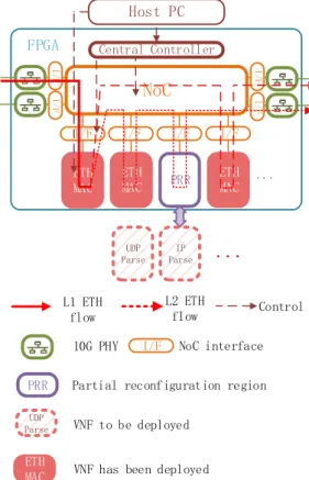
The architecture of the proposed NFV platform is shown in Fig. 1. It is composed of a number of partial reconfigurable regions (PRRs), which are interconnected by a NoC. The 10Gbps PHY is also connected to the NoC to receive and transmit data to off chip network. A central controller is also included to control the NoC router(s) and orchestrate the virtual network function switch-over process. As the logic circuit of VNFs can be reconfigured, the network developers are able to perform VNF design deep into logic circuit level.
A dynamic NoC is adopted as interconnect architecture between PRRs in the proposed NFV platform. It is composed of a number of NoC routers. NoC interfaces are also included between PRRs and NoC routers to control the traffic. Each PRR is identified by a unique NoC address. The destination address of a packet is added in the NoC interface. And the NoC routers forward the packet according to the NoC address. The architecture of the NoC router and interface will be further introduced in section IV. The external 10 Gbps network ports are also connected with the NoC. All PRRs are decoupled from PHYs and directly attached to NoC as pluggable independently accessible regions. This enables for a protocol independent system that can support different protocols from Layer 2 and upwards. The host PC controls the reconfiguration of the platform through the on-chip central controller. Updated
information is transferred from the host PC through the central controller to the NoC to enable the update of routing algorithms. The central controller is also responsible to perform the protocol reconfiguration process. The detailed information of the process is given in section V.
L1 ETH flow
PRR Partial reconfiguration region UDP
Parse VNF to be deployed ETH
MAC VNF has been deployed
10G PHY
L2 ETH
flow Control
I/F NoC interface
Central Controller FPGA PRR PRR PRR PRR ...
NoC
ETH MAC ETH MAC Host PC UDP Parse IP Parse...
I/F I/F I/F I/F
ETH MAC I/ F I /F I/F I/ F
Fig. 1. Overview architecture of the NFV platform.
Since all VNFs including Layer 2 MAC are only attached to NoC (network-attached functions) they are clearly decoupled from the high speed I/Os. This allows for a highly flexible system that can deploy and involve the VNFs where and when needed. VNF engines can be reconfigured on PRRs on per port, per independent flow, or per virtual network basis. PRRs can be also reconfigured into on-demand VNFs at run-time and critically without disruption of the service or loss of data.
Therefore, a reconfigurable NFV platform with the following features is established: a) Network developers can design their VNFs deep into logic circuit level, which can potentially increase performance. b) Network developers can also reconfigure the switch type of the system between circuit switch and Layer 2 packet switch to serve the required service with appropriate capabilities and performance. c) Network developers can enhance the already deployed protocols and functions in real-time and in packet loss free manner.
IV. IMPLEMENTATION
The implementation detail of the NoC router and interface is shown in Fig. 2. A NoC interface is needed at the edge of NoC to bridge PRRs and PHYs with NoC routers. The NoC routers can be connected to build up diverse topology between PRRs. The NoC routers and interfaces are connected following the AXI4-stream handshake standard.
FIFO Routing table NoC router
...
Other router Buffer Traffic Update Ready Valid PRR NoC Des AXI4-stream AXI4-lite...
ETH/NoC tableETH Des NoC Interface Update Central controller FIFOCtrl Traffic buffer flag
PHY
...
PRR...
PHY...
Traffic buffer flag
AXI 4 -stream switch DATA
Fig. 2. The architecture of NoC router and end point buffer
The Ethernet address is translated into NoC address according to the table in the NoC interface. This table can be updated by the central controller through AXI4-lite interface. The NoC address is transferred in parallel with the packet (in the user channel of AXI4-stream) until reaching its required PRR. The NoC interface is also responsible to control the traffic. FIFO is added to temporarily store the traffic during the reconfiguration of the platform. The FIFO can be controlled by the central controller to buffer or release the traffic at runtime. When the traffic has been buffered, the traffic buffer flag will be raised by the NoC interface. The flag will be transferred by NoC routers to notify that the traffic has been buffered (No further data will arrive until the traffic is released). This flag will be used in the reconfiguration process in section V to indicate that the traffic has been completely buffered.
A routing table between NoC destination and output port is stored in each NoC router. When a packet is received by a NoC router, its NoC destination is extracted and the packet is forwarded to the related output port according to the routing table. The routing table can be updated dynamically by the
central controller through an AXI4-lite interface. The traffic buffer flag is transferred by the NoC routers. This flag is also given to the central controller to indicate that the last clock cycle of data has arrived (No further data will be received until the traffic is released).
V. PACKET LOSS FREEE RECONFIGURATION PROCESS
A reconfiguration process that supports packet loss free protocol reconfiguration is introduced in this section. Instead of only having one active PRR, a backup (empty) PRR is introduced. As the NoC does not forward any data to the backup PRR, the bit file for this PRR can be downloaded without disturbing the existing traffic. When a switch-over of VNF (i.e. transfer from UDP parser to IP parser) is requested, partial bit file of the requested VNF will be firstly deployed on the backup PRR. During the download of the partial bit file of the backup PRR, the rest of the platform including the active PRR will not be interrupted. The backup PRR with requested VNF will not come into use until the reconfiguration of backup PRR is finished. When the reconfiguration of backup PRR is finished (the requested VNF is ready), the NoC will forward the related dataflow to the backup PRR and stop forwarding data to the previous active PRR. The previous backup PRR become active and the previous active PRR takes the role of the new backup PRRfor future protocolupgrades and switch-overs.
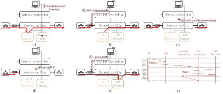
As shown in Fig.3, the PRRs, NoC routers and interfaces should be orchestrated appropriately during the reconfiguration process. The central controller takes the responsibility to orchestrate the reconfiguration process. The process takes five steps to reconfigure the VNF. Partial bit file of the requested VNF is downloaded from host PC to the backup PRR in the first step (a). The traffic will have to be buffered in the second step (b) to avoid any packet loss. The NoC routers report the traffic buffer flag to the central controller to confirm that the traffic
c) ④ Update NoC Network on Chip IP Parser UDP Parser Central controller d)
②start buffering traffic
Network on Chip IP Parser UDP Parser Central controller b) ⑤ release traffic Network on Chip IP Parser UDP Parser Central controller e) ① Partial bitstream download Network on Chip IP Parser Backup PRR Central controller a)
③ Traffic is buffered completely Network on Chip IP Parser UDP parser Central controller ① ② ③ ④ ⑤ f)
PC PRR controllerCentral interfacesNoC RoutersNoC
Fig. 3. Reconfiguration process. a) The partial bit file is download into the backup PRR. b) The traffic is buffered. c) traffic already exiting in NoC has been completely transferred to the destination. d) The NoC is reconfigured to forward data to new processor. e) the traffic is released. f) the overall
has been completely buffered in step (c). The central controller then updates the routing table of the NoC in step (d). The data will then be released from the NoC interface and will be routed through the new requested NFV PRR in step (e). The overall orchestration process is shown in Fig.3.f.
The proposed process is able to increase the performance of the reconfiguration since the platform is still functioning during the partial bit file download period. Only when the NoC is being updated, traffic should be buffered. The traffic buffer time required to enable free packet loss for common reconfiguration process and the proposed process is compared in the following paragraphs.
In the standard partial reconfiguration process, the traffic has to be buffered during the download period of the bit file, since the PRR is not funcitoning. The download time of partial bit files according to their sizes are shown in Fig.4. The partial reconfiguration is performed through Vivado with the standard configuration of the reconfiguration controller (ICAPE2 at 100 MHz). As the partial bit file needs to be forwarded to the reconfiguration controller, the size of the bit file has a strong influence on the reconfiguration time. Table I shows the resource utilization, partial bit file size and download time of a set of VNF processors. As indicated, the Ethernet parser with minimum partial bit file size takes 1785 microseconds. The Ethernet MAC needs the maximum download time which is 2525 microseconds. Following the standard reconfiguration process, these times translate to excessive buffering resources as shown in Fig.4.
Fig. 4. Time and buffer needed for packet loss free partial bitfile download TABLE I. RESOURCE UTILIZATION AND PARTIAL BIT FILE SIZE VNF processor Flip flop LUT file size (KB)Partial bit Download time (us)
Ethernet MAC 2700 3245 1010 2525
Ethernet Parser 493 290 714 1785
IP Parser 1268 1001 792 1980
UDP Parser 2072 1451 846 2115
During the proposed reconfiguration process, traffic needs to be buffered only when the NoC is being updated, since the previous VNF is still functioning in the active PRR. The buffer time required is the update time of the NoC. As introduced in section III, the routing table is updated through AXI4-lite
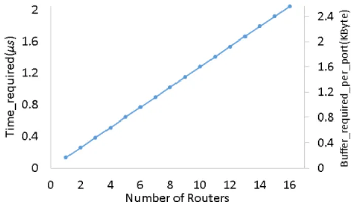
interface. The size of the update data will have an influence on the time. The size of each destination-output port pair of the routing table is 8 bytes. Each NoC router contains 32 destination-output port pairs. The number of destination-output port pairs need to be updated depends on the deployed routing algorithm. The time and buffer required to reconfigure the NoC is shown in Fig.5.
Fig. 5. Time and buffer needed for packet loss free NoC Update time
The result shows that the time to update NoC is at
microsecond’s level (Fig.5) comparing to the common partial bit file download time which is at the level of hundreds of microseconds or even milliseconds (Fig.4). As the NFV platform is still able to process data during the download time of the partially bit file, time needed to buffer the traffic can be reduced with the proposed reconfiguration process. Therefore, the proposed partial reconfiguration process enables a packet loss free reconfiguration (switch-over) between VNFs where no data is lost during the process. With the proposed process, the network developer will be able to change VNFs on demand without stopping the traffic.
VI. EXPERIMENTAL DEMONSTRATION
This section demonstrates use cases of the proposed NFV platform. Reconfiguration between a circuit switch and a Layer 2 Ethernet packet switch is demonstrated. The latency of the circuit and packet switch is measured. Reconfiguration between IP (Layer 3) and UDP (Layer 4) parsers is also demonstrated. Parsed packets are counted to prove that no packet is lost during the reconfiguration process.
TABLE II. RESOURCE UTILIZATION
Component Flip Flop LUT BRAM
NoC interface 446 267 3
NoC router 10398 22268 0
Central controller 994 432 2
The resource requirement for a star topology NoC with 15 ports is shown in table II. The proposed NFV platform is implemented on the NetFPGA SUME board with Xilinx Virtex-7 690T FPGA chip [15]. The traffic is generated and analyzed by the Network Master Pro MT1000A from Anritsu [16]. The latency accuracy of the traffic analyzer is 100 nanoseconds. The traffic analyzer has also a built in 100
nanoseconds latency (measured when using it in a loopback mode). This has been removed in the following result. The network analyzer is connected with the 10Gbps SFP+ optical transceivers of the NetFPGA through one-meter single mode fiber. As the latency accuracy of the traffic analyzer is 100 nanoseconds, the latency of the fiber (5 nanoseconds per meter) is ignored.
A. Reconfiguration between circuit and packet switch
Fig.6 shows the reconfiguration process from circuit switch to packet switch. In the circuit switch mode, the NoC forwards data from the input port directly to the output port. Ethernet MAC does not process any data. When the platform is reconfigured to packet switch mode, the routing table of NoC are dynamically updated to forward input data to an Ethernet MAC. Ethernet packets are extracted and sent to different output ports according to their Ethernet address information.
Central Controller FPGA PRR PRR PRR PRR ... NoC ETH MAC ETH MAC Host PC ETH MAC ETH MAC Central Controller FPGA PRR PRR PRR PRR ... NoC ETH MAC ETH MAC Host PC ETH MAC ETH MAC
Fig. 6. Reconfigure from circuit switch to Ethernet packet switch
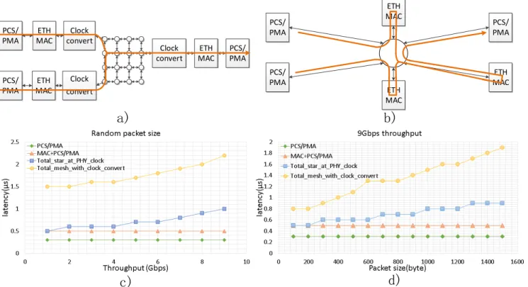
The performance of a 2x2 Ethernet packet switch has been further analyzed. A NoC with mesh topology has been set up as shown in Fig.7.a. Clock convert modules are inserted between
MAC (156.25 MHz) and the NoC (200 MHz). The NoC does not have to perform at the frequency of MAC with this configuration. Also the NoC can have good connectivity to interconnect a large number of PRRs. The influence of throughput on the latency is shown in Fig.7.c (1.2 microseconds and 1.9 microseconds for minimum and maximum throughput respectively). And the influence of packet size is shown in Fig.7.d. A NoC with star topology has been set up as shown in Fig.7.b. In this case, the NoC is operating at the frequency of MAC, so the clock convert modules are removed. The maximum number of input-output pairs of a NoC router is 15, so maximum 15 modules (I/O PHYs and PRRs) can be interconnected with this configuration. As shown in Fig.7.c and Fig.7.d, although the connectivity is limited, this configuration achieves ultra-low latency (500 nanoseconds and 1 microsecond for minimum and maximum throughput respectively). This implementation delivers a latency reduction compared to the 4x4 mesh configuration in the order of 58% and 47% under minimum and maximum throughput respectively.
B. Packet Loss Free Reconfiguration between Funcitons
A reconfiguration between IP and UDP parser is demonstrated. The process of the demonstration is shown in Fig.8. IP parser is deployed in the active PRR in the initial stage (a). Then in stage (b), the UDP parser is deployed in the backup PRR. After the proposed reconfiguration process, the traffic is forwarded there to make the deployed UDP parser processing the traffic. Then the previous active PRR is configured into UDP parser and the traffic switches back to the active PRR by the proposed reconfiguration process.
c)
a)
d)
ETH MAC ETH MAC ETH MAC Clock convert Clock convert Clock convert PCS/ PMA PCS/ PMA PCS/ PMAb)
ETH MAC PCS/ PMA PCS/ PMA ETH MAC PCS/ PMA ETH MACFig. 7 The performance of a 2x2 Ethernet packet switch. a) The experiment set up for a 4x4 mesh NoC running at 200MHz with clock converters. b) The experiment set up for a star NoC running at PHY frequency (156.25MHz), clock converter is not requirement. c) The relationship between throughput and
Central Controller FPGA PRR PRR PRR PRR ... NoC ETH MAC ETH MAC Host PC UDP c) a) b) Central Controller FPGA PRR PRR PRR PRR ... NoC ETH MAC ETH MAC Host PC IP Central Controller FPGA PRR PRR PRR ... NoC ETH MAC ETH MAC Host PC IP UDP
Fig. 8. The reconfiguration process demonstrated. a) The initial stage of the platform. b) The requested UDP parser is deployed on the backup PRR
and become active. c) Switch back to the orginal PRR.
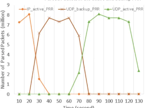
The record of parsed packets in each PRR is shown in Fig.9. During 20th to 30th second, the backup PRR start parsing the traffic. From 30th to 70th second, the backup PRR is processing packets. The original active PRR is then reconfigured into UDP parser and then reused after 70 seconds, while the backup PRR becomes available again for future reconfigurations. The number of total packets is recorded by the traffic analyzer which is 77518546. The number of packets parsed in each PRR is 42708766 (original active PRR) and 34809780 (original backup PRR). There is no packet lost throughout the whole process as the total number of parsed packets (with no errors) is equal to the total number of transmit packets (34809780 + 42708766 = 77518546).
Fig. 9. Packet loss free switch-over between UDP and IP parsers.
VII. CONCLUSION
An FPGA-based network function virtualization platform has been proposed in this paper. It has been implemented to demonstrate a protocol independent switch that can evolve from one protocol to another in real-time and without service disruption and loss of data. The platform allows a network developer to design and deploy the logic circuit of any VNF on the platform. Partially reconfiguration has been adopted to enable the runtime reconfiguration of VNFs. A reconfiguration process has been proposed and implemented to realize packet loss free function reconfiguration. The platform can keep performing without loss of data during the download time of the
partial bit file. Reconfiguration between circuit switch and Layer 2 Ethernet packet switch is demonstrated. Ethernet MAC can be bypassed in the circuit switch mode to reduce latency. The implemented NFV 2x2 switch has very high performance in terms of latency (0.3 microseconds for circuit switch, maximum 1 microsecond for Layer 2 Ethernet) while delivering 9.8 Gbps throughout per 10 Gbps port. Reconfiguration between IP and UDP parser has also been demonstrated. The result shows that all the packets are parsed without losing data.
VIII. ACKNOWLEDGEMENT
This work is supported by the EC H2020 dredbox project with grant agreement No.687632.
REFERENCES
[1] N. Zilberman, P. M. Watts, C. Rotsos, and A. W. Moore, “Reconfigurable Network
Systems and Software-Defined Networking,” Proc. IEEE, vol. 103, no. 7, pp. 1102–
1124, Jul. 2015.
[2] D. Kreutz, F. M. V. Ramos, P. E. Veríssimo, C. E. Rothenberg, S. Azodolmolky,
and S. Uhlig, “Software-Defined Networking: A Comprehensive Survey,” Proc.
IEEE, vol. 103, no. 1, pp. 14–76, Jan. 2015.
[3] Y. Li and M. Chen, “Software-Defined Network Function Virtualization: A Survey,”
IEEE Access, vol. 3, pp. 2542–2553, 2015.
[4] Network Functions Virtualisation (NFV);Virtual Network Functions Architecture, ETSI GS NFV-SWA 001 V1.1.1, 2014-12.
[5] A. Daglis, S. Novaković, E. Bugnion, B. Falsafi, and B. Grot, “Manycore Network
Interfaces for in-memory rack-scale computing,” in 2015 ACM/IEEE 42nd Annual
International Symposium on Computer Architecture (ISCA), 2015, pp. 567–579.
[6] G. Brebner, “Softly Defined Networking,” in Proceedings of the Eighth ACM/IEEE
Symposium on Architectures for Networking and Communications Systems, New York, NY, USA, 2012, pp. 1–2.
[7] M. Attig and G. Brebner, “400 Gb/s Programmable Packet Parsing on a Single
FPGA,” in Proceedings of the 2011 ACM/IEEE Seventh Symposium on
Architectures for Networking and Communications Systems, Washington, DC, USA, 2011, pp. 12–23.
[8] S. Zhou, W. Jiang, and V. K. Prasanna, “A flexible and scalable high-performance
OpenFlow switch on heterogeneous SoC platforms,” in 2014 IEEE 33rd
International Performance Computing and Communications Conference (IPCCC), 2014, pp. 1–8.
[9] L. Kekely, V. Puš, P. Benáček, and J. Kořenek, “Trade-offs and progressive adoption
of FPGA acceleration in network traffic monitoring,” in 2014 24th International
Conference on Field Programmable Logic and Applications (FPL), 2014, pp. 1–4. [10] D. Koch, J. Torresen, C. Beckhoff, D. Ziener, C. Dennl, V. Breuer, J. Teich, M.
Feilen, and W. Stechele, “Partial reconfiguration on FPGAs in practice; Tools and
applications,” in ARCS Workshops (ARCS), 2012, 2012, pp. 1–12.
[11] L. Jianwen and J. C. Chuen, “Partially reconfigurable matrix multiplication for area and time efficiency on FPGAs,” in Euromicro Symposium on Digital System
Design, 2004. DSD 2004, 2004, pp. 244–248.
[12] S. Byma, J. G. Steffan, H. Bannazadeh, A. L. Garcia, and P. Chow, “FPGAs in the Cloud: Booting Virtualized Hardware Accelerators with OpenStack,” in 2014 IEEE
22nd Annual International Symposium on Field-Programmable Custom Computing Machines (FCCM), 2014, pp. 109–116.
[13] D. Koch, C. Beckhoff, and J. Teich, “ReCoBus-Builder-A novel tool and technique
to build statically and dynamically reconfigurable systems for FPGAS,” in 2008
International Conference on Field Programmable Logic and Applications, 2008, pp. 119–124.
[14] A. Weichslgartner, S. Wildermann, and J. Teich, “Dynamic decentralized mapping
of tree-structured applications on NoC architectures,” in 2011 Fifth IEEE/ACM
International Symposium on Networks on Chip (NoCS), 2011, pp. 201–208. [15] Noa Zilberman, Yury Audzevich, G. Adam Covington, Andrew W. Moore,
'NetFPGA SUME: Toward 100 Gbps as Research Commodity,' IEEE Micro, vol.34, no.5, pp.32,41, September-October 2014.
[16] “Network Master Pro MT1000A- Anritsu Europe.” [Online]. Available:
https://www.anritsu.com/en-GB/test-measurement/products/mt1000a. [Accessed: 20-Jul-2016].