1
Chapter 1
1 Tension and Compression in
Bars
1.1 Stress... 7
1.2 Strain... 13
1.3 Constitutive Law ... 14
1.4 Single Bar under Tension or Compression... 18
1.5 Statically Determinate Systems of Bars ... 29
1.6 Statically Indeterminate Systems of Bars ... 33
1.7 Supplementary Examples... 40
1.8 Summary ... 46
Objectives: In this textbook about theMechanics of Ma-terialswe investigate the stressing and the deformations of elastic structures subject to applied loads. In the first chapter we will re-strict ourselves to the simplest structural members, namely, bars under tension or compression.
In order to treat such problems, we need kinematic relations and a constitutive law to complement the equilibrium conditions which are known from Volume 1. The kinematic relations represent the geometry of the deformation, whereas the behaviour of the elastic material is described by the constitutive law. The students will learn how to apply these equations and how to solve statically determinate as well as statically indeterminate problems.
D. Gross et al., Engineering Mechanics 2,
1.1 Stress 7
1.1
1.1 Stress
Let us consider a straight bar with a constant cross-sectional area
A. The line connecting the centroids of the cross sections is called theaxisof the bar. The ends of the bar are subjected to the forces
F whose common line of action is the axis (Fig. 1.1a).
The external load causes internal forces. The internal forces can be visualized by an imaginary cut of the bar (compare Volu-me 1, Section 1.4). They are distributed over the cross section (see Fig. 1.1b) and are calledstresses. Being area forces, they have the dimension force per area and are measured, for example, as mul-tiples of the unit MPa (1 MPa = 1 N/mm2). The unit “Pascal”
(1 Pa = 1 N/m2) is named after the mathematician and physicist
Blaise Pascal (1623–1662); the notion of “stress” was introduced by Augustin Louis Cauchy (1789–1857). In Volume 1 (Statics) we only dealt with the resultant of the internal forces (= normal for-ce) whereas now we have to study the internal forces (= stresses).
b a d e c ϕ τ σ c ϕ F F F F F σ F F c F c F F τσ A c A∗=cosAϕ N Fig. 1.1
In order to determine the stresses we first choose an imaginary cut c−c perpendicular to the axis of the bar. The stresses are shown in the free-body diagram (Fig. 1.1b); they are denoted by
σ. We assume that they act perpendicularly to the exposed surface
A of the cross section and that they are uniformly distributed. Since they are normal to the cross section they are callednormal stresses. Their resultant is the normal forceN shown in Fig. 1.1c (compare Volume 1, Section 7.1). Therefore we haveN=σAand the stressesσcan be calculated from the normal forceN:
σ= N
A . (1.1)
In the present example the normal forceN is equal to the applied forceF. Thus, we obtain from (1.1)
σ= F
A. (1.2)
In the case of a positive normal force N (tension) the stress σ
is then positive (tensile stress). Reversely, if the normal force is negative (compression) the stress is also negative (compressive stress).
Let us now imagine the bar being sectioned by a cut which is not orthogonal to the axis of the bar so that its direction is given by the angle ϕ (Fig. 1.1d). The internal forces now act on the exposed surface A∗ = A/cosϕ. Again we assume that they are uniformly distributed. We resolve the stresses into a componentσ
perpendicular to the surface (the normal stress) and a component
τ tangential to the surface (Fig. 1.1e). The component τ which actsinthe direction of the surface is calledshear stress.
Equilibrium of the forces acting on the left portion of the bar yields (see Fig. 1.1e)
→: σA∗cosϕ+τ A∗sinϕ−F = 0, ↑: σA∗sinϕ−τ A∗cosϕ= 0.
Note that we have to write down the equilibrium conditions for theforces, notfor thestresses. WithA∗=A/cosϕwe obtain
σ+τtanϕ= F
A, σtanϕ−τ= 0.
Solving these two equations forσandτ yields
σ= 1 1 + tan2ϕ F A, τ = tanϕ 1 + tan2ϕ F A.
1.1 Stress 9
It is practical to write these equations in a different form. Using the standard trigonometric relations
1 1 + tan2ϕ = cos 2ϕ , cos2ϕ=1 2(1 + cos 2ϕ), sinϕcosϕ = 1 2sin 2ϕ
and the abbreviation σ0 = F/A (= normal stress in a section
perpendicular to the axis) we finally get
σ= σ0
2 (1 + cos 2ϕ), τ =
σ0
2 sin 2ϕ . (1.3) Thus, the stresses depend on the direction of the cut. If σ0 is
known, the stressesσandτ can be calculated from (1.3) for arbi-trary values of the angleϕ. The maximum value ofσis obtained for ϕ= 0, in which case σmax =σ0; the maximum value ofτ is
found forϕ=π/4 for whichτmax=σ0/2.
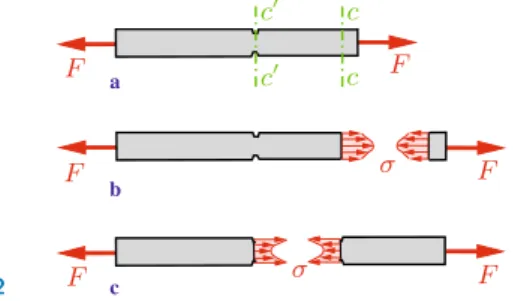
If we section a bar near an end which is subjected to a concen-trated forceF (Fig. 1.2a, sectionc−c) we find that the normal stress is not distributed uniformly over the cross-sectional area. The concentrated force produces high stresses near its point of application (Fig. 1.2b). This phenomenon is known asstress con-centration. It can be shown, however, that the stress concentration is restricted to sections in the proximity of the point of application of the concentrated force: the high stresses decay rapidly towards the average valueσ0as we increase the distance from the end of the
bar. This fact is referred to asSaint-Venant’s principle(Adh´emar Jean Claude Barr´e de Saint-Venant, 1797–1886).
Fig. 1.2 b a c c c c c F F F F F F σ σ
The uniform distribution of the stress is also disturbed by holes, notches or any abrupt changes (discontinuities) of the geometry. If, for example, a bar has notches the remaining cross-sectional area (section c−c) is also subjected to a stress concentration (Fig. 1.2c). The determination of these stresses is not possible with the elementary analysis presented in this textbook.
Let us now consider a bar with only aslighttaper (compare Ex-ample 1.1). In this case the normal stress may be calculated from (1.1) with a sufficient accuracy. Then the cross-sectional area A
and the stressσdepend on the location along the axis. If volume forces act in the direction of the axis in addition to the concentra-ted forces, then the normal forceN also depends on the location. Introducing the coordinate xin the direction of the axis we can write:
σ(x) = N(x)
A(x). (1.4) Here it is also assumed that the stress is uniformly distributed over the cross section at a fixed value ofx.
In statically determinate systems we can determine the normal force N from equilibrium conditions alone. If the cross-sectional areaA is known, the stressσcan be calculated from (1.4). Stati-cally indeterminate systems will be treated in Section 1.4.
In engineering applications structures have to be designed in such a way that a given maximum stressing is not exceeded. In the case of a bar this requirement means that the absolute value of the stress σ must not exceed a givenallowable stress σallow : |σ| ≤σallow. (Note that the allowable stresses for tension and for
compression are different for some materials.) The required cross section Areq of a bar for a given load and thus a known normal
forceN can then be determined fromσ=N/A:
Areq = | N| σallow
. (1.5)
This is referred to as dimensioning of the bar. Alternatively, the allowable load can be calculated from |N| ≤σallowA in the case
1.1 Stress 11
Note that a slender bar which is subjected to compression may fail due to buckling before the stress attains an inadmissibly large value. We will investigate buckling problems in Chapter 7.
E1.1 Example 1.1 A bar (lengthl) with a circular cross section and a
slight taper (linearly varying from radiusr0 to 2r0) is subjected
to the compressive forcesF as shown in Fig. 1.3a.
Determine the normal stress σ in an arbitrary cross section perpendicular to the axis of the bar.
b a l F F x r(x) F r0 2r0 F Fig. 1.3
Solution We introduce the coordinatex, see Fig. 1.3b. Then the radius of an arbitrary cross section is given by
r(x) =r0+ r0 l x=r0 1 +x l .
Using (1.4) with the cross sectionA(x) =π r2(x) and the constant
normal forceN=−F yields
σ = N A(x)= −F πr2 0 1 + x l 2.
The minus sign indicates thatσis a compressive stress. Its value at the left end (x = 0) is four times the value at the right end (x=l).
E1.2 Example 1.2 A water tower (height H, density ) with a cross
section in the form of a circular ring carries a tank (weightW0)
as shown in Fig. 1.4a. The inner radiusri of the ring is constant.
Determine the outer radius r in such a way that the normal stressσ0 in the tower is constant along its height. The weight of
0000000
0000000
1111111
1111111
a b ri H dx A σ0 σ0 W0 x r r(x) A+dA dW ri Fig. 1.4 Solution We consider the tower to be a slender bar. The relation-ship between stress, normal force and cross-sectional area is given by (1.4). In this example the constant compressive stress σ=σ0is given; the normal force (here counted positive as compressive force) and the areaAare unknown.
The equilibrium condition furnishes a second equation. We in-troduce the coordinatexas shown in Fig. 1.4b and consider a slice element of length dx. The cross-sectional area of the circular ring as a function ofxis
A=π(r2−r2i) (a)
where r = r(x) is the unknown outer radius. The normal force at the locationx is given byN =σ0A (see 1.4). At the location x+ dx, the area and the normal force areA+ dAandN+ dN =
σ0(A+ dA).
The weight of the element is dW = gdV where dV =Adx
is the volume of the element. Note that terms of higher order are neglected (compare Volume 1, Section 7.2.2). Equilibrium in the vertical direction yields
↑: σ0(A+ dA)− gdV −σ0A= 0 → σ0dA− g Adx= 0.
Separation of variables and integration lead to
dA A = g σ0 dx → ln A A0 = g x σ0 → A=A0e g x σ0 . (b)
1.2 Strain 13
The constant of integrationA0follows from the condition that the
stress at the upper end of the tower (forx= 0 we haveN =W0)
also has to be equal toσ0: W0 A0 =σ0 → A0= W0 σ0 . (c)
Equations (a) to (c) yield the outer radius:
r2(x) =ri2+ W0
π σ0
e g xσ0 .
1.2
1.2 Strain
We will now investigate the deformations of an elastic bar. Let us first consider a bar with a constant cross-sectional area which has the undeformed length l. Under the action of tensile forces (Fig. 1.5) it gets slightly longer. The elongation is denoted by Δl
and is assumed to be much smaller than the original lengthl. As a measure of the amount of deformation, it is useful to introduce, in addition to the elongation, the ratio between the elongation and the original (undeformed) length:
ε= Δl
l . (1.6)
The dimensionless quantity ε is called strain. If, for example, a bar of the length l = 1 m undergoes an elongation of Δl = 0.5 mm then we haveε= 0.5·10−3. This is a strain of 0.05%. If the
bar gets longer (Δl >0) the strain is positive; it is negative in the case of a shortening of the bar. In what follows we will consider only small deformations:|Δl| l or|ε| 1, respectively.
The definition (1.6) for the strain is valid only ifεis constant over the entire length of the bar. If the cross-sectional area is not
F F
l Δl
deformed bar undeformed bar dx u dx+(u+du)−u x u+du Fig. 1.6
constant or if the bar is subjected to volume forces acting along its axis, the strain may depend on the location. In this case we have to use alocalstrain which will be defined as follows. We consider an element of the bar (Fig. 1.6) instead of the whole bar. It has the length dxin the undeformed state. Its left end is located atx, the right end atx+ dx. If the bar is elongated, the cross sections undergo displacements in thex-direction which are denoted byu. They depend on the location:u=u(x). Thus, the displacements areuat the left end of the element andu+ duat the right end. The length of the elongated element is dx+ (u+ du)−u= dx+ du. Hence, the elongation of the element is given by du. Now the local strain can be defined as the ratio between the elongation and the undeformed length of the element:
ε(x) = du
dx. (1.7)
If the displacement u(x) is known, the strain ε(x) can be de-termined through differentiation. Reversely, ifε(x) is known, the displacement u(x) is obtained through integration.
The displacement u(x) and the strain ε(x) describe the geo-metry of the deformation. Therefore they are called kinematic quantities. Equation (1.7) is referred to as a kinematic relation.
1.3
1.3 Constitutive Law
Stresses are quantities derived from statics; they are a measure for the stressing in the material of a structure. On the other hand, strains are kinematic quantities; they measure the deformation
1.3 Constitutive Law 15
of a body. However, the deformation depends on the load which acts on the body. Therefore, the stresses and the strains are not independent. The physical relation that connects these quantities is calledconstitutive law. It describes the behaviour of the material of the body under a load. It depends on the material and can be obtained only with the aid of experiments.
One of the most important experiments to find the relationship between stress and strain is the tension or compression test. Here, a small specimen of the material is placed into a testing machine and elongated or shortened. The forceF applied by the machine onto the specimen can be read on the dial of the machine; it causes the normal stressσ=F/A. The change Δl of the lengthl
of the specimen can be measured and the strainε= Δl/lcan be calculated.
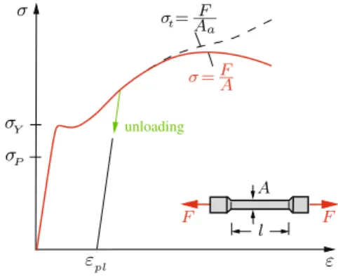
The graph of the relationship between stress and strain is shown schematically (not to scale) for a steel specimen in Fig. 1.7. This graph is referred to as stress-strain diagram. One can see that for small values of the strain the relationship is linear (straight line) and the stress is proportional to the strain. This behaviour is valid until the stress reaches the proportional limit σP. If the stress exceeds the proportional limit the strain begins to increase more rapidly and the slope of the curve decreases. This continues until the stress reaches theyield stressσY. From this point of the stress-strain diagram the strain increases at a practically constant stress: the material begins toyield. Note that many materials do
Fig. 1.7 unloading σY σP l ε A εpl σ σ=FA σt=AF a F F
not exhibit a pronounced yield point. At the end of the yielding the slope of the curve increases again which shows that the material can sustain an additional load. This phenomenon is calledstrain hardening.
Experiments show that an elongation of the bar leads to a re-duction of the cross-sectional areaA. This phenomenon is referred to aslateral contraction. Whereas the cross-sectional area decrea-ses uniformly over the entire length of the bar in the case of small stresses, it begins to decrease locally at very high stresses. This phenomenon is called necking. Since the actual cross section Aa
may then be considerably smaller than the original cross section
A, the stressσ=F/Adoes not describe the real stress any more. It is therefore appropriate to introduce the stressσt=F/Aawhich
is calledtrue stressorphysical stress. It represents the true stress in the region where necking takes place. The stressσ=F/Ais re-ferred to asnominalorconventionalorengineering stress. Fig. 1.7 shows both stresses until fracture occurs.
Consider a specimen being firstloadedby a force which causes the stress σ. Assume thatσ is smaller than the yield stress σY,
i.e., σ < σY. Subsequently, the load is again removed. Then the
specimen will return to its original length: the strain returns to zero. In addition, the curves during the loading and the unloa-ding coincide. This behaviour of the material is calledelastic; the behaviour in the regionσ ≤σP is referred to as linearly elastic. Now assume that the specimen is loaded beyond the yield stress, i.e., until a stress σ > σY is reached. Then the curve during the
unloading is a straight line which is parallel to the straight line in the linear-elastic region, see Fig. 1.7. If the load is completely removed the strain does not return to zero: aplastic strainεpl
re-mains after the unloading. This material behaviour is referred to asplastic.
In the following we will always restrict ourselves to a linearly-elastic material behaviour. For the sake of simplicity we will refer to this behaviour shortly as elastic, i.e., in what follows “elastic” always stands for “linearly elastic”. Then we have the linear rela-tionship
1.3 Constitutive Law 17
Table 1.1 Material Constants
Material E in MPa αT in 1/◦C Steel 2,1·105 1,2·10−5
Aluminium 0,7·105 2,3·10−5
Concrete 0,3·105 1,0·10−5 Wood (in fibre direction) 0,7... 2,0·104 2,2 ... 3,1·10−5
Cast iron 1,0·105 0,9·10−5
Copper 1,2·105 1,6·10−5
Brass 1,0·105 1,8·10−5
σ=E ε (1.8)
between the stress and the strain. The proportionality factorEis called modulus of elasticity or Young’s modulus (Thomas Young, 1773–1829). The constitutive law (1.8) is calledHooke’s lawafter Robert Hooke (1635–1703). Note that Robert Hooke could not present this law in the form (1.8) since the notion of stress was introduced only in 1822 by Augustin Louis Cauchy (1789–1857). The relation (1.8) is valid for tension and for compression: the modulus of elasticity has the same value for tension and compres-sion. However, the stress must be less than the proportional limit
σP which may be different for tension or compression.
The modulus of elasticityEis a constant which depends on the material and which can be determined with the aid of a tension test. It has the dimension of force/area (which is also the dimen-sion of stress); it is given, for example, in the unit MPa. Table 1.1 shows the values ofE for several materials at room temperature. Note that these values are just a guidance since the modulus of elasticity depends on the composition of the material and on the temperature.
A tensile or a compressive force, respectively, causes the strain
ε=σ/E (1.9)
in a bar, see (1.8). Changes of the length and thus strains are not only caused by forces but also by changes of the temperature. Experiments show that the thermal strain εT is proportional to the change ΔT of the temperature if the temperature of the bar is changed uniformly across its section and along its length:
εT =αTΔT . (1.10) The proportionality factor αT is called coefficient of thermal ex-pansion. It is a material constant and is given in the unit 1/◦C. Table 1.1 shows several values ofαT.
If the change of the temperature is not the same along the entire length of the bar (if it depends on the location) then (1.10) represents the local strainεT(x) =αTΔT(x).
If a bar is subjected to a stressσas well as to a change ΔTof the temperature, the total strainεis obtained through a superposition of (1.9) and (1.10):
ε= σ
E +αTΔT . (1.11)
This relation can also be written in the form
σ=E(ε−αTΔT). (1.12)
1.4
1.4 Single Bar under Tension or Compression
There are three different types of equations that allow us to de-termine the stresses and the strains in a bar: the equilibrium con-dition, the kinematic relation and Hooke’s law. Depending on the problem, the equilibrium condition may be formulated for the en-tire bar, a portion of the bar (see Section 1.1) or for an element of the bar. We will now derive the equilibrium condition for an
1.4 Single Bar under Tension or Compression 19 a b N N+dN dx n(x) x F2 F1 ndx x dxx+dx l Fig. 1.8
element. For this purpose we consider a bar which is subjected to two forcesF1 andF2 at its ends and to a line loadn=n(x), see
Fig. 1.8a. The forces are assumed to be in equilibrium. We imagine a slice element of infinitesimal length dxseparated from the bar as shown in Fig. 1.8b. The free-body diagram shows the normal forces N and N + dN, respectively, at the ends of the element; the line load is replaced by its resultantndx(note thatnmay be considered to be constant over the length dx, compare Volume 1, Section 7.2.2). Equilibrium of the forces in the direction of the axis of the bar
→: N+ dN+ndx−N= 0 yields theequilibrium condition
dN
dx +n= 0. (1.13)
In the special case of a vanishing line load (n ≡ 0) the normal force in the bar is constant.
Thekinematic relationfor the bar is (see (1.7))
ε= du dx,
andHooke’s lawis given by (1.11):
ε= σ
E +αTΔT .
If we insert the kinematic relation andσ=N/Ainto Hooke’s law we obtain
du
dx = N
EA+αTΔT . (1.14)
This equation relates the displacementsu(x) of the cross sections and the normal forceN(x). It may be called the constitutive law for the bar. The quantityEAis known asaxial rigidity. Equations (1.13) and (1.14) are the basic equations for a bar under tension or compression.
The displacementuof a cross section is found through integra-tion of the strain:
ε= du dx → du= εdx → u(x)−u(0) = x 0 εd¯x .
The elongation Δl follows as the difference of the displacements at the endsx=landx= 0 of the bar:
Δl=u(l)−u(0) =
l 0
εdx . (1.15)
Withε= du/dxand (1.14) this yields
Δl= l 0 N EA +αTΔT dx . (1.16)
In the special case of a bar (lengthl) with constant axial rigidity (EA = const) which is subjected only to forces at its end (n ≡
0, N = F) and to a uniform change of the temperature (ΔT = const), the elongation is given by
Δl= F l
EA+αTΔT l . (1.17)
1.4 Single Bar under Tension or Compression 21
Δl= F l
EA, (1.18)
and ifF = 0, (1.17) reduces to
Δl=αTΔT l . (1.19)
If we want to apply these equations to specific problems, we have to distinguish between statically determinate and statical-ly indeterminate problems. In astatically determinatesystem we can always calculate the normal force N(x) with the aid of the equilibrium condition. Subsequently, the strainε(x) follows from
σ=N/Aand Hooke’s lawε=σ/E. Finally, integration yields the displacement u(x) and the elongation Δl. A change of the tem-perature causes only thermal strains(no stresses!) in a statically determinate system.
In a statically indeterminateproblem the normal force cannot be calculated from the equilibrium condition alone. In such pro-blems the basic equations (equilibrium condition, kinematic re-lation and Hooke´s law) are a system of coupled equations and have to be solved simultaneously. A change of the temperature in general causes additional stresses; they are calledthermal stresses. Finally we will reduce the basic equations to a single equation for the displacement u. If we solve (1.14) for N and insert into (1.13) we obtain
(EA u)=−n+ (EA αTΔT). (1.20a) Here, the primes denote derivatives with respect to x. Equation (1.20a) simplifies in the special caseEA= const and ΔT = const to
EA u=−n . (1.20b) If the functionsEA(x),n(x) and ΔT(x) are given, the displace-mentu(x) of an arbitrary cross section can be determined through integration of (1.20). The constants of integration are calculated from the boundary conditions. If, for example, one end of the bar
is fixed thenu= 0 at this end. If, on the other hand, one end of the bar can move and is subjected to a forceF0, then applying (1.14)
andN =F0yields the boundary conditionu=F0/EA+αTΔT.
This reduces to the boundary conditionu = 0 in the special case of a stress-free end (F0 = 0) of a bar whose temperature is not
changed (ΔT = 0).
Frequently, one or more of the quantities in (1.20) are given through different functions of x in different portions of the bar (e.g., if there exists a jump of the cross section). Then the bar must be divided into several regions and the integration has to be performed separately in each of theses regions. In this case the constants of integration can be calculated from boundary conditi-ons and matching conditiconditi-ons (compare Volume 1, Section 7.2.4).
a b
000
111
l W N(x) W∗=l−x l W x Fig. 1.9As an illustrative example of a statically determinate system let us consider a slender bar (weightW, cross-sectional area A) that is suspended from the ceiling (Fig. 1.9a). First we determine the normal force caused by the weight of the bar. We cut the bar at an arbitrary positionx(Fig. 1.9b). The normal forceN is equal to the weightW∗ of the portion of the bar below the imaginary cut. Thus, it is given byN(x) =W∗(x) =W(l−x)/l. Equation (1.4) now yields the normal stress
σ(x) = N(x) A = W A 1−x l .
1.4 Single Bar under Tension or Compression 23
Accordingly, the normal stress in the bar varies linearly; it decre-ases from the valueσ(0) = W/Aat the upper end to σ(l) = 0 at the free end.
The elongation Δlof the bar due to its own weight is obtained from (1.16): Δl= l 0 N EAdx= W EA l 0 1−x l dx= 1 2 W l EA.
It is half the elongation of a bar with negligible weight which is subjected to the forceW at the free end.
We may also solve the problem by applying the differential equation (1.20b) for the displacementsu(x) of the cross sections of the bar. Integration with the constant line loadn=W/lyields
EA u=− W l , EA u =− W l x+C1, EA u =− W 2l x 2+C 1x+C2.
The constants of integrationC1 andC2 can be determined from
the boundary conditions. The displacement of the cross section at the upper end of the bar is equal to zero:u(0) = 0. Since the stress σ vanishes at the free end, we have u(l) = 0. This leads to C2 = 0 andC1=W. Thus, the displacement and the normal
force are given by
u(x) =1 2 W l EA 2 x l − x2 l2 , N(x) =EA u(x) =W 1−x l .
Sinceu(0) = 0, the elongation is equal to the displacement of the free end:
Δl=u(l) = 1 2
W l EA.
The stress is obtained as σ(x) = N(x) A = W A 1−x l .
As an illustrative example of a statically indeterminate system let us consider a bar which is placed stress-free between two rigid walls (Fig. 1.10a). It has the cross-sectional areas A1 and A2,
respectively. We want to determine the support reactions if the temperature of the bar is raised uniformly by an amount ΔT in region{.
The free-body diagram (Fig. 1.10b) shows the twosupport re-actionsB andC. They cannot be calculated from onlyone equi-librium condition: →: B−C= 0. b a = + c "1"Ŧ System "0"Ŧ System
0
0
0
1
1
1
00
00
11
11
0
0
1
1
00
00
00
11
11
11
0
0
0
1
1
1
0
0
1
1
l l ΔT ΔT X B ΔT C C B C B 1 2 Fig. 1.10Therefore we have to take into account the deformation of the bar. The elongations in the regions{and|are given by (1.16) with
N =−B =−C: Δl1= N l EA1 +αTΔT l , Δl2= N l EA2
(the temperature in region|is not changed).
The bar is placed between tworigidwalls. Thus, its total elon-gation Δl has to vanish:
Δl= Δl1+ Δl2= 0.
This equation expresses the fact that the geometry of the defor-mation has to be compatible with the restraints imposed by the supports. Therefore it is calledcompatibility condition.
1.4 Single Bar under Tension or Compression 25
The equilibrium condition and the compatibility condition yield the unknown support reactions:
N l EA1 +αTΔT l+ N l EA2 = 0 →B=C=−N =EA1A2αTΔT A1+A2 .
The problem may also be solved in the following way. In a first step we generate a statically determinate system. This is achie-ved by removing one of the supports, for example supportC. The action of this support on the bar is replaced by the action of the forceC =X which is as yet unknown. Note that one of the sup-ports, for exampleB, is needed to have a statically determinate system. The other support, C, is in excess of the necessary sup-port. Therefore the reactionCis referred to as being aredundant reaction.
Now we need to consider two different problems. First, we in-vestigate the statically determinate system subjected to the given load (here: the change of the temperature in region{) which is referred to as “0“-system or primary system (Fig. 1.10c). In this system the change of the temperature causes the thermal elon-gation Δl(0)1 (normal force N = 0) in region { ; the elongation in region| is zero. Thus, the displacementu(0)C of the right end point of the bar is given by
u(0)C = Δl1(0)=αTΔT l .
Secondly we consider the statically determinate system subjec-ted only to forceX. It is called “1“-system and is also shown in Fig. 1.10c. Here the displacementu(1)C of the right end point is
u(1)C = Δl1(1)+ Δl(1)2 =− X l
EA1 − X l EA2
.
Both the applied load (here: ΔT) as well as the forceX act in the given problem (Fig. 1.10a). Therefore, the total displacement
uCat point Cfollows throughsuperposition:
Since the rigid wall in the original system prevents a displacement atC, the geometric condition
uC= 0
has to be satisfied. This leads to
αTΔT l− X l EA1 − X l EA2 = 0 → X =C=EA1A2αTΔT A1+A2 .
Equilibrium at the free-body diagram (Fig. 1.10b) yields the se-cond support reactionB=C.
E1.3 Example 1.3 A solid circular steel cylinder (cross-sectional area
AS, modulus of elasticity ES, length l) is placed inside a copper
tube (cross-sectional areaAC, modulus of elasticityEC, lengthl).
The assembly is compressed between a rigid plate and the rigid floor by a forceF (Fig. 1.11a).
Determine the normal stresses in the cylinder and in the tube. Calculate the shortening of the assembly.
b a
000
000
111
111
0000
0000
1111
1111
0000
1111
l F S C FC FS F FS FC Fig. 1.11 Solution We denote the compressive forces in the steel cylinder and in the copper tube byFS andFC, respectively (Fig. 1.11b).Equilibrium at the free-body diagram of the plate yields
FC+FS=F . (a)
Since equilibrium furnishes only one equation for the two unknown forces FS and FC, the problem is statically indeterminate. We
1.4 Single Bar under Tension or Compression 27
obtain a second equation by taking into account the deformation of the system. The shortenings (here counted positive) of the two parts are given according to (1.18) by
ΔlC= FCl
EAC, ΔlS = FSl
EAS (b)
where, for simplicity, we have denoted the axial rigidityECAC of
the copper tube byEAC and the axial rigidityESAS of the steel
cylinder byEAS.
The plate and the floor are assumed to be rigid. Therefore the geometry of the problem requires that the shortenings of the cop-per tube and of the steel cylinder coincide. This gives the compa-tibility condition
ΔlC= ΔlS. (c)
Solving the Equations (a) to (c) yields the forces
FC = EAC
EAC+EAS F , FS =
EAS
EAC+EAS F . (d)
The compressive stresses follow according to (1.2):
σC = EC
EAC+EASF , σS =
ES
EAC+EASF .
Inserting (d) into (b) leads to the shortening: ΔlC= ΔlS = F l
EAC+EAS .
E1.4 Example 1.4 A copper tube|is placed over a threaded steel bolt
{of length l. The pitch of the threads is given by h. A nut fits snugly against the tube without generating stresses in the system (Fig. 1.12a). Subsequently, the nut is givenn full turns and the temperature of the entire assembly is increased by the amount ΔT. The axial rigidities and the coefficients of thermal expansion of the bolt and the tube are given.
Determine the force in the bolt. a b l nh l−nh X X 1 2 2 1 X X Fig. 1.12 Solution After the nut has been turned it exerts a compressive force X on the tube which causes a shortening of the tube. Ac-cording to Newton’s third axiom (action = reaction) a force of equal magnitude and opposite direction acts via the nut on the bolt which elongates. The free-body diagrams of bolt and tube are shown in Fig. 1.12b.
The problem is statically indeterminate since force F cannot be determined from equilibrium alone. Therefore we have to take into account the deformations. The length of the bolt after the nut has been turned, see the free-body diagram in Fig. 1.12b, is given byl1=l−n h. Its elongation Δl1 follows from
Δl1=
X(l−n h)
EA1
+αT1ΔT(l−n h).
Sincen hl, this can be reduced to Δl1=
X l EA1
+αT1ΔT l .
The change of length Δl2 of the tube (l2=l) is obtained from
Δl2=− X l EA2
+αT2ΔT l .
The length of the bolt and the length of the tube have to coincide after the deformation. This yields the compatibility condition
1.5 Statically Determinate Systems of Bars 29
Solving the equations leads to the force in the bolt:
X l EA1 + l EA2 + (αT1 − αT2)ΔT l=n h → X =n h−(αT1−αT2)ΔT l 1 EA1 + 1 EA2 l . 1.5
1.5 Statically Determinate Systems of Bars
In the preceding section we calculated the stresses and deformati-ons of single slender bars. We will now extend the investigation to trusses and to structures which consist of bars and rigid bodies. In this section we will restrict ourselves to statically determinate systems where we can first calculate the forces in the bars with the aid of the equilibrium conditions. Subsequently, the stresses in the bars and the elongations are determined. Finally, the displa-cements of arbitrary points of the structure can be found. Since it is assumed that the elongations are small as compared with the lengths of the bars, we can apply the equilibrium conditions to theundeformedsystem.
As an illustrative example let us consider the truss in Fig. 1.13a. Both bars have the axial rigidityEA. We want to determine the displacement of pinC due to the applied forceF. First we calcu-late the forcesS1 andS2 in the bars. The equilibrium conditions,
applied to the free-body diagram (Fig. 1.13b), yield
↑: S2sinα−F = 0 ←: S1+S2cosα= 0 → S1=− F tanα, S2= F sinα.
According to (1.17) the elongations Δli of the bars are given by
Δl1= S1l1 EA =− F l EA 1 tanα, Δl2= S2l2 EA = F l EA 1 sinαcosα.
Bar 1 becomes shorter (compression) and bar 2 becomes longer (tension). The new positionC of pinC can be found as follows. We consider the bars to be disconnected at C. Then the system becomes movable: bar 1 can rotate about pointA; bar 2 can rotate about pointB. The free end points of the bars then move along circular paths with radiil1+ Δl1andl2+ Δl2, respectively. Point C is located at the point of intersection of these arcs of circles (Fig. 1.13c). d c a b
00
00
00
00
00
00
11
11
11
11
11
11
α 2 α 1 α 2 α 2 1 1 l B A C C u v F C S2 S1 Δl2 Δl1 C Δl2 C Δl1 C F Fig. 1.13The elongations are small as compared with the lengths of the bars. Therefore, within a good approximation the arcs of the circles can be replaced by their tangents. This leads to the displa-cement diagram as shown in Fig. 1.13d. If this diagram is drawn to scale, the displacement of pinC can directly be taken from it. We want to apply a “graphic-analytical” solution. It suffices then to draw a sketch of the diagram. Applying trigonometric relati-ons we obtain the horizontal and the vertical components of the
1.5 Statically Determinate Systems of Bars 31 displacement: u=|Δl1|= F l EA 1 tanα, v = Δl2 sinα+ u tanα = F l EA 1 + cos3α sin2αcosα. (1.21)
To determine the displacement of a pin of a truss with the aid of a displacement diagram is usually quite cumbersome and can be recommended only if the truss has very few members. In the case of trusses with many members it is advantageous to apply an energy method (see Chapter 6).
The method described above can also be applied to structures which consist of bars and rigid bodies.
E1.5 Example 1.5 A rigid beam (weightW) is mounted on three elastic
bars (axial rigidityEA) as shown in Fig. 1.14a.
Determine the angle of slope of the beam that is caused by its weight after the structure has been assembled.
a b d c 1 β α α α α 2 3 α 1 2 a a a a W EA A A B W B S3 S1 S2 vA vB Δl1 Δl2 A A vA Fig. 1.14
Solution First we calculate the forces in the bars with the aid of the equilibrium conditions (Fig. 1.14b):
S1=S2=− W
4 cosα, S3=− W
2 .
Withl1=l2=l/cosαandl3=l we obtain the elongations:
Δl1= Δl2= S1l1 EA =− W l 4EAcos2α, Δl3= S3l3 EA =− W l 2EA.
Point B of the beam is displaced downward by vB = |Δl3|. To determine the vertical displacement vA of point A we sketch a displacement diagram (Fig. 1.14c). First we plot the changes Δl1
and Δl2 of the lengths in the direction of the respective bar. The
lines perpendicular to these directions intersect at the displaced positionA of pointA. Thus, its vertical displacement is given by
vA=|Δl1|/cosα.
Since the displacements vA and vB do not coincide, the beam does not stay horizontal after the structure has been assembled. The angle of slopeβis obtained with the approximation tanβ≈β
(small deformations) andl=acotαas (see Fig. 1.14d)
β= vB−vA a = 2 cos3α−1 4 cos3α W cotα EA . If cos3α > 1 2 (or cos 3α < 1
2), then the beam is inclined to the
right (left). In the special case cos3α= 1
2, i.e.α= 37.5◦, it stays
horizontal.
E1.6 Example 1.6 The truss in Fig. 1.15a is subjected to a force F. Given:E= 2·102 GPa,F = 20 kN.
Determine the cross-sectional area of the three members so that the stresses do not exceed the allowable stressσallow= 150 MPa
and the displacement of supportB is smaller than 0.5‰ of the length of bar 3.
Solution First we calculate the forces in the members. The equili-brium conditions for the free-body diagrams of pinCand support
1.6 Statically Indeterminate Systems of Bars 33 b a 1 3 45◦ 2 45◦ 45◦ l l F l S1 S2=S1 F B S2 A B C C S3 Fig. 1.15 S1=S2=− √ 2 2 F , S3= F 2 .
The stresses do not exceed the allowable stress if
|σ1|=|S1| A1 ≤σallow,|σ2|=| S2| A2 ≤σallow, σ3= S3 A3 ≤σallow.
This leads to the cross-sectional areas
A1=A2= | S1| σallow = 94.3 mm2, A 3= S3 σallow = 66.7 mm2. (a)
In addition, the displacement of supportB has to be smaller than 0.5 ‰ of the length of bar 3. This displacement is equal to the elongation Δl3=S3l3/EA3 of bar 3 (supportA is fixed).
From Δl3<0.5·10−3l3we obtain Δl3 l3 = S3 EA3 <0.5·10−3 → A3> 2S3 E 10 3= F E10 3= 100mm2.
Comparison with (a) yields the required areaA3= 100 mm2.
1.6
1.6 Statically Indeterminate Systems of Bars
We will now investigate statically indeterminate systems for which the forces in the bars cannot be determined with the aid of the equilibrium conditions alone since the number of the unknown quantities exceeds the number of the equilibrium conditions. In such systems the basic equations (equilibrium conditions,
kinema-tic equations (compatibility) and Hooke’s law) are coupled equa-tions.
Let us consider the symmetrical truss shown in Fig. 1.16a. It is stress-free before the load is applied. The axial rigiditiesEA1, EA2, EA3 =EA1 are given; the forces in the members are
un-known. The system is statically indeterminate to the first degree (the decomposition of a force into three directions cannot be done uniquely in a coplanar problem, see Volume 1, Section 2.2). The two equilibrium conditions applied to the free-body diagram of pinK (Fig. 1.16b) yield
→: −S1sinα+S3sinα= 0 → S1=S3, ↑: S1cosα+S2+S3cosα−F = 0→ S1=S3=
F−S2
2 cosα .
(a)
The elongations of the bars are given by Δl1= Δl3= S1l1 EA1 , Δl2= S2l EA2 . (b)
To derive the compatibility condition we sketch a displacement diagram (Fig. 1.16c) from which we find
b a c
=
+
d "1"Ŧ System "0"Ŧ System000000
000000
111111
111111
00000
00000
11111
11111
00
00
11
11
000000
111111
0000000
1111111
1 2 3 α α α 1 2 3 1 3 α α K K S1 S3=S1 F Δl1 Δl3 Δl2 K S2 l F F X X K F Fig. 1.161.6 Statically Indeterminate Systems of Bars 35
Δl1= Δl2cosα . (c)
With (a), (b) andl1=l/cosαwe obtain from (c)
(F−S2)l 2EA1cos2α = S2l EA2 cosα which leads to S2= F 1 + 2EA1 EA2 cos3α .
The remaining two forces in the bars follow from (a):
S1=S3= EA1 EA2 cos2α 1 + 2EA1 EA2 cos3α F .
Note that now the vertical displacementv of pinKcan also be written down: v= Δl2= S2l EA2 = F l EA2 1 + 2EA1 EA2 cos3α .
The problem may also be solved using the method of super-position. In a first step we remove bar 2 to obtain a statically determinate system, the “0“-system. It consists of the two bars 1 and 3 and it is subjected to the given force F (Fig. 1.16d). The forcesS1(0)andS3(0)in these bars follow from the equilibrium conditions as
S1(0)=S3(0)= F 2 cosα.
The corresponding elongations are obtained withl1=l/cosα:
Δl(0)1 = Δl(0)3 =S (0) 1 l1 EA1 = F l 2EA1cos2α . (d)
In a second step we consider the statically determinate system under the action of an unknown force X (“1“-system, see also Fig. 1.16d). Note that this force acts in the opposite direction on bar 2 (actio = reactio). Now we get
S1(1) =S(1)3 =− X 2 cosα, S (1) 2 =X , Δl1(1)= Δl(1)3 =− Xl 2 EA1cos2α , Δl(1)2 = Xl EA2 . (e)
The total elongation of the bars is obtained through superposition of the systems “0“ and “1“:
Δl1= Δl3= Δl1(0)+ Δl (1)
1 , Δl2= Δl2(1). (f)
The compatibility condition (c) is again taken from the displace-ment diagram (Fig. 1.16c). It leads with (d) - (f) to the unknown forceX =S2(1)=S2: F l 2 EA1cos2α − X l 2EA1cos2α = X l EA2 cosα →X =S2= F 1 + 2EA1 EA2 cos3α .
The forcesS1 andS3 follow from superposition:
S1=S3=S (0) 1 +S (1) 1 = EA1 EA2 cos2 α 1 + 2EA1 EA2 cos3α F .
A system of bars is statically indeterminate of degree nif the number of the unknowns exceeds the number of the equilibrium conditions by n. In order to determine the forces in the bars of such a system,ncompatibility conditions are needed in addition to the equilibrium conditions. Solving this system of equations yields the unknown forces in the bars.
A statically indeterminate system of degreencan also be solved with the method of superposition. Then n bars are removed in order to obtain a statically determinate system. The action of the
1.6 Statically Indeterminate Systems of Bars 37
bars which are removed is replaced by the action of the static redundants Si = Xi. Next n+ 1 different auxiliary systems are
considered. The given load acts in the “0“-system, whereas the “i“-system (i = 1,2, ..., n) is subjected only to the force Xi. In
each of the statically determinate auxiliary problems the forces in the bars and thus the elongations can be calculated. Applying the
ncompatibility conditions yields a system of equations for then
unknown forcesXi. The forces in the other bars can subsequently
be determined through superposition.
E1.7 Example 1.7 A rigid beam (weight negligible) is suspended from
three vertical bars (axial rigidityEA) as shown in Fig. 1.17a. Determine the forces in the originally stress-free bars if a) the beam is subjected to a forceF (ΔT = 0),
b) the temperature of bar 1 is changed by ΔT (F = 0).
a b c
000000000
111111111
2 1 3 l F ΔT Δl1 Δl2 Δl3 A S1 F S2 S3 a a/2a/2 Fig. 1.17Solution The system is statically indeterminate to the first degree: there are only two equilibrium conditions for the three unknown forcesSj (Fig. 1.17b). a) If the structure is subjected to forceF
the equilibrium conditions are
↑ : S1+S2+S3−F= 0,
A : − a
2 F+a S2+ 2a S3= 0.
(a)
The elongations of the bars are given by (ΔT = 0) Δl1= S1l EA, Δl2= S2l EA, Δl3= S3l EA. (b)
We sketch a displacement diagram (Fig. 1.17c) and find the com-patibility condition
Δl2=
Δl1+ Δl3
2 . (c)
Now we have six equations for the three forcesSj and the three
elongations Δlj . Solving for the forces yields S1= 7 12F , S2= 1 3F , S3= 1 12F .
b) If bar 1 is heated (F = 0), the equilibrium conditions are
↑ : S1+S2+S3= 0,
A: aS2+ 2aS3= 0,
(a)
and the elongations are given by Δl1= S1l EA + αTΔT l , Δl2= S2l EA, Δl3= S3l EA. (b)
The compatibility condition (c) is still valid. Solving (a), (b) and (c) yields S1=S3=− 1 6EA αTΔT , S2= 1 3EA αTΔT .
E1.8 Example 1.8 To assemble the truss in Fig. 1.18a, the free end of bar 3 (lengthl−δ,δl) has to be connected with pinC.
a) Determine the necessary forceF acting at pinC (Fig. 1.18b). b) Calculate the forces in the bars after the truss has been
assem-bled and forceF has been removed.
a
0000000
b c0000000
0000000
0000000
0000000
1111111
1111111
1111111
1111111
1111111
0000000
0000000
0000000
0000000
0000000
1111111
1111111
1111111
1111111
1111111
1 2 3 δ 1 δ 2 3 l l C F C∗ l v∗ Δl3 Fig. 1.181.6 Statically Indeterminate Systems of Bars 39
Solution a) The force F causes a displacement of pin C. The horizontal componentvof this displacement has to be equal toδ
to allow assembly. The required force follows with α= 45◦ from (1.21): v= F l EA 1 +√2/4 √ 2/4 =δ → F= EA δ (2√2 + 1)l.
b) The force F is removed after the truss has been assembled. Then pin C undergoes another displacement. Since now a force
S3 in bar 3 is generated, pin C does not return to its original
position: it is displaced to positionC∗ (Fig. 1.18c). The distance between pointsC andC∗ is given by
v∗=S3l
EA
1 +√2/4
√
2/4 . The compatibility condition
v∗+ Δl3=δ
can be taken from Fig. 1.18c. With the elongation Δl3= S3(l−δ) EA ≈ S3l EA of bar 3 we reach S3l EA 1 +√2/4 √ 2/4 + S3l EA =δ → S3= EA δ 2(√2 + 1)l.
The other two forces follow from the equilibrium condition at pin
C:
S1= √
1.7
1.7 Supplementary Examples
Detailed solutions to the following examples are given in (A) D. Gross et al. Formeln und Aufgaben zur Technischen Mechanik 2, Springer, Berlin 2010, or (B) W. Hauger et al. Aufgaben zur Technischen Mechanik 1-3, Springer, Berlin 2008.
E1.9 Example 1.9 A slender bar (density ρ, modulus of elasticity
E) is suspended from its upper end as shown in Fig. 1.19. It has a rectangular cross
secti-on with a csecti-onstant depth and a linearly varying width. The cross section at the upper end isA0.
Determine the stress σ(x) due to the force F and the weight of the bar. Calculate the minimum stress σmin and its
location.
000
111
000
111
A0 ρ F F a l x Fig. 1.19 Results:see (A) σ(x) = F l+ρg A0 2 (x2−a2) A0x , σmin=ρgx∗, x∗= 2F l ρgA0 − a2.E1.10 Example 1.10 Determine the elongation Δl of the tapered circular shaft (modulus of ela-sticity E) shown in Fig. 1.20 if it is subjected to a tensile forceF. d D l Fig. 1.20 Result:see (A) Δl= 4F l πEDd.
1.7 Supplementary Examples 41
E1.11 Example 1.11 A slender bar (weight
W0, modulus of elasticity E,
coef-ficient of thermal expansion αT) is
suspended from its upper end. It just touches the ground as shown in Fig. 1.21 without generating a con-tact force.
000
000
111
111
000
000
111
111
x E W0 αT l A Fig. 1.21Calculate the stressσ(x) if the temperature of the bar is uni-formly increased by ΔT. Determine ΔT so that there is compres-sion in the whole bar.
Results:see (A) σ(x) = W0 A 1−x l −EαTΔT , ΔT > W0 EAαT . E1.12 Example 1.12 The bar (cross
sectional area A) shown in Fig. 1.22 is composed of steel and aluminium. It is pla-ced stress-free between two ri-gid walls. Given: Est/Eal =
3, αst/αal= 1/2.
0000
1111
00
00
00
11
11
11
0
0
0
0
1
1
1
1
C F steel aluminium a l−a A B Fig. 1.22a) Calculate the support reactions if the bar is subjected to a forceF at pointC.
b) Calculate the normal force in the whole bar if it is subjected only to a change of temperature ΔT (F = 0).
Results:see (A) a)NA=−F3(l−a) 3l−2a, NB =F a 3l−2a, b)N =− 2l−a 3l−2aEstαstAΔT .
E1.13 Example 1.13 The column in Fig. 1.23 consists of reinfor-ced concrete. It is subjected to a tensile force F. Given:
Est/Ec= 6, Ast/Ac= 1/9.
Determine the stresses in the steel and in the concrete and the elongation Δl of the column if
000
000
111
111
Est, Ast cut cross section F Ec, Ac l Fig. 1.23a) the bonding between steel and concrete is perfect,
b) the bonding is damaged so that only the steel carries the load.
Results:see (A) a)σst= 4F A, σc = 2 3 F A, Δl= 2 5 F l EAst, b)σst = 10 F A, Δl= F l EAst.
E1.14 Example 1.14 A slender bar (densityρ, modulus of elasticityE, lengthl) is suspended from its upper end as shown in Fig. 1.24. It has a rectangular cross section
with a constant depth a. The widthbvaries linearly from 2b0
at he fixed end tob0at the free
end.
Determine the stressesσ(x) and σ(l) and the elongation Δl of the bar due to its own weight.
000
111
x l 2b0 b0 a cut b(x) cross section Fig. 1.24 Results:see (B) σ(x) = 1 2ρg (2l+x)x l+x , σ(l) = 3ρgl 4 , Δl= ρgl2 4E (3−2 ln 2).1.7 Supplementary Examples 43
E1.15 Example 1.15 A rigid chair
(weight negligible) is sup-ported by three bars (axi-al rigidity EA) as shown in Fig. 1.25. It is subjected to a forceF at pointB.
a) Calculate the forces Si
in the bars and the elongati-ons Δli of the bars.
b) Determine the displace-ment of pointC.
000000000000
000000000000
000000000000
000000000000
000000000000
000000000000
000000000000
000000000000
000000000000
000000000000
000000000000
111111111111
111111111111
111111111111
111111111111
111111111111
111111111111
111111111111
111111111111
111111111111
111111111111
111111111111
1 2 3 D C F B a a a a Fig. 1.25 Results:see (A) a)S1=F, S2= 0, S3=− √ 2F, Δl1= F a EA, Δl2= 0, Δl3=−2 F a EA, b)uC = 0, vC= 2 √ 2F a EA. E1.16 Example 1.16 Two bars (axialrigidity EA) are pin-connected and supported at C (Fig. 1.26). a) Calculate the support re-action atC due to the forceF.
b) Determine the displace-ment of the support.
000000000
000000000
111111111
111111111
1 2 l α C F Fig. 1.26Results:see (A) a)C=sinαcos
2α 1 + cos3αF, b)vC= 1 1 + cos3α F l EA.
E1.17 Example 1.17 Consider a thin circular ring (modulus of elasticity
E, coefficient of thermal expansionαT, internal radiusr−δ, δr)
with a rectangular cross section (width b, thickness t r). The ring is heated in order to increase its radius which makes it possible to place it over a rigid wheel with radiusr.
Determine the necessary change of temperature ΔT. Calculate the normal stressσin the ring and the pressureponto the wheel after the temperature has regained its original value.
Results:see (B) ΔT = δ αTr, σ=E δ r, p=σ t r.
E1.18 Example 1.18 The two rods (axial rigidityEA) shown in Fig. 1.27 are pin-connected at K. The system is subjec-ted to a vertical forceF.
Calculate the displacement of pinK. 30◦ F K l 2l Fig. 1.27 Results:see (B) u=√3F l EA, v= F l EA.
E1.19 Example 1.19 The structure shown in Fig. 1.28 consists of a rigid beamBCand two ela-stic bars (axial rigidityEA). It is subjected to a forceF.
Calculate the displacement of pinC. a B C F 2 1 30◦ a Fig. 1.28 Results:see (B) u= 0, v= 3√3F a EA.
1.7 Supplementary Examples 45
E1.20 Example 1.20 Fig. 1.29 shows
a freight elevator. The cable (lengthl, axial rigidity (EA)1)
of the winch passes over a smooth pinK. A crate (weight
W) is suspended at the end of the cable (see Example 2.13 in Volume 1). The axial rigidity (EA)2 of the two bars 1 and 2
is given.
000000
000000
000000
000000
000000
000000
000000
000000
111111
111111
111111
111111
111111
111111
111111
111111
30◦ winch l K H W 45◦ a 1 2 Fig. 1.29Determine the displacements of pin K and of the end of the cable (pointH) due to the weight of the crate.
Results:see (B) u= 6.69 W a (EA)2 , v= 3.86 W a (EA)2 , f = 2.83 W a (EA)2 + W l (EA)1 . E1.21 Example 1.21 To assemble
the truss (axial rigidity
EA of the three bars) in Fig. 1.30 the end pointP of bar 2 has to be connected with pinK. Assume δh. Determine the forces in the bars after the truss has been assembled.
0000000
1111111
0000000
1111111
K α α h P δ K α α h P δ 2 1 3 Fig. 1.30 Results:see (B) S1=S3=− EAδcos2α h(1 + 2 cos3α), S2= 2EAδcos3α h(1 + 2 cos3α).1.8
1.8 Summary
• Normal stress in a section perpendicular to the axis of a bar:
σ=N/A ,
N normal force,Across-sectional area.
• Strain:
ε= du/dx , |ε| 1,
udisplacement of a cross section. Special case of uniform strain:ε= Δl/l.
• Hooke’s law: σ=E ε , E modulus of elasticity. • Elongation: Δl= l 0 N EA+αTΔT dx ,
EA axial rigidity,αT coefficient of thermal expansion, ΔT change of temperature.
Special cases:
N =F, ΔT = 0, EA= const → Δl= F l
EA , N = 0, ΔT = const → Δl=αTΔT l . • Statically determinate system of bars: normal forces, stresses,
strains, elongations and displacements can be calculated con-secutively from the equilibrium conditions, Hooke’s law and kinematic equations. A change of the temperature does not cause stresses.
• Statically indeterminate system: the equations (equilibrium conditions, kinematic equations and Hooke’s law) are coupled equations. A change of the temperature in general causes ther-mal stresses.