Li, Guoshuai (2020) Experimental studies on shock wave interactions with
flexible surfaces and development of flow diagnostic tools. PhD thesis.
https://theses.gla.ac.uk/81703/
Copyright and moral rights for this work are retained by the author
A copy can be downloaded for personal non-commercial research or study,
without prior permission or charge
This work cannot be reproduced or quoted extensively from without first
obtaining permission in writing from the author
The content must not be changed in any way or sold commercially in any
format or medium without the formal permission of the author
When referring to this work, full bibliographic details including the author,
title, awarding institution and date of the thesis must be given
Enlighten: Theses
EXPERIMENTAL STUDIES ON SHOCK WAVE INTERACTIONS
WITH FLEXIBLE SURFACES AND DEVELOPMENT OF FLOW
DIAGNOSTIC TOOLS
Submitted in fulfilment of the requirements for the degree of
Doctor of Philosophy
Guoshuai Li
School of Engineering
College of Science and Engineering
University of Glasgow
I. Author’s Declaration
I declare that, except where explicit reference is made to the contribution of others, this dissertation is the result of my own work and has not been submitted for any other degree at the University of Glasgow or any other institution.
Signature: __________
II. Abstract
Nowadays, light-weight composite materials have increasingly used for high-speed flight vehicles to improve their performance and efficiency. At supersonic speed, sonic fatigue, panel flutter, severe instabilities, and even catastrophic structural failure would occur due to the shock wave impingement on several flexible components of a given structural system either internally or externally. Therefore, investigation on shock wave interaction with flexible surfaces is crucial for the safety and performance of high-speed flight vehicles. This work aims to investigate the mechanism of shock wave interaction with flexible surfaces with and without the presence of the boundary layer. The first part involves the shock wave generated by supersonic starting jets interaction with flexible surfaces and the other one focuses on shock wave and boundary layer interaction (SBLI) over flexible surfaces.
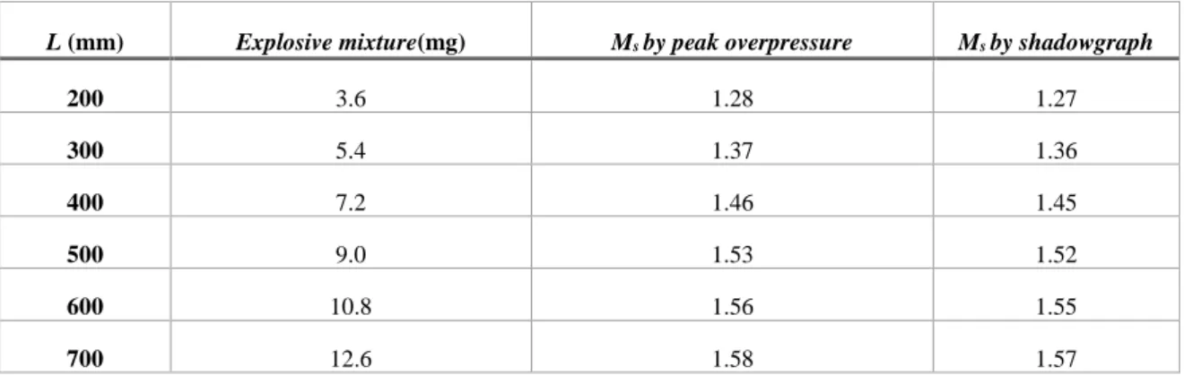
A novel miniature and cost-effective shock tube driven by detonation transmission tubing was designed and manufactured to simulate the supersonic starting jet and investigate the interaction of a supersonic starting jet with flexible surfaces. To investigate the characterization of this novel type shock tube, the pressure-time measurement in the driven section and the time-resolved shadowgraph were performed. The result shows that the flow structure from the open end of the shock tube driven by detonation transmission tubing agrees with that of conventional compressed-gas driven shock tubes. Moreover, this novel type of shock tube has good repeatability of less than 3% with a Mach number range of 1.29-1.58 when the weight of the NONEL explosive mixture varies from 3.6mg to 12.6mg.
An unsteady background oriented schlieren (BOS) measurement system and a sprayable Polymer-Ceramic unsteady pressure sensitive paint (PC-PSP) system were developed. The preliminary BOS result in a supersonic wind tunnel shows that the sensitivity of the BOS system is good enough to visualize weak density variations caused by expansion waves, boundary layer, and weak oblique shocks. Additionally, compared with the commercial PC-PSP from Innovative Scientific Solutions Incorporated (ISSI), the in-house developed unsteady PSP system has higher pressure sensitivity, lower temperature sensitivity, and photo-degradation rate.
To identify the shock movement, distortion and unsteadiness during the processes of the supersonic starting jet impingement and shock wave boundary layer interaction (SBLI) over flexible surfaces, an image processing scheme involving background subtraction in the frequency domain, filtering, resampling, edge detection, adaptive threshold, contour detection, feature extraction, and fitting was proposed and applied to process shadowgraph and schlieren sequences automatically. A large shadowgraph data set characterized by low signal to noise ratio (SNR) and small spatial resolution (312×260-pixel), was used to validate the proposed scheme. The result proves that the aforementioned image processing scheme can detect, track, localize, and fit shock waves in a subpixel accuracy.
The mechanism of the interaction between the initial shock wave from a supersonic starting jet and flexible surfaces was investigated based on a square shock tube driven by detonation transmitting tube. Compared with that of the solid plate case, flexible surfaces can delay the shock reflection process because of the flexible panel deformation generated by the pressure difference between the top and the bottom. The delay time is around 8µs in the case of 0.1mm thick flexible surface, whereas it declines to around 4µs in the case of 0.3mm thick flexible surface because of the lower flexibility and deformation magnitude. However, interestingly, the propagation velocity of the reflected shock wave is basically the same for the solid plate and flexible panels, which means the flexible surface doesn’t reduce the strength of the reflection wave, although it delays its propagation. Also, there is not an apparent difference in the velocity of the reflected shock wave in the case of different incident shock Mach numbers when Ms varying from 1.22 to 1.54. These experimental results from this study are
useful for validating numerical codes that are used for understanding fluid-structure interaction processes.
III. Acknowledgements
My deepest gratitude goes to my supervisors Professor Konstantinos Kontis and Professor Zhaolin Fan for all the guidance and encouragement they have offered me throughout my studies. Thanks to all the things they have taught me, without which I would not be where I am today.
I would like to thank CARDC for funding this research. Special acknowledgments also go to my leaders and colleagues from the High Speed Institute of CARDC for all their help and support during my PhD.
My special thanks to my close friends and colleagues Dr. Takahiro Ukai, Dr. Hossein Zare-Behtash, Dr. Sriram Rengarajan Chitra, Dr. Kin Hing Lo, and Dr. Craig White for all their technical help and guidance. Many thanks to other PhDs in my research group, Mr. Andrew Russell, Mr. Kosuke Fujiwara, Mr. Michael Wojewodka, Miss Sarah Fitzpatrick, Miss Francesca Gnani, Mr. Thomas Andreou Mr. Shaun Skinner, Mr. Andrew Cusick, Mr. Hassam Guevara Jelid, Mr. Muhammed Burak Agir, Mr. Senthil Kumar, Mr. Fan Jiang and Mr. Ziqu Cao for helping me and being with me in the long hours I spent in the labs but more importantly for all the laughs we had.
I especially acknowledge Dr. Richard Green for providing access of the commercial PSP system from ISSI, Professor Lucas for offering the high-speed camera, Professor Antony Kelly for lending the SiPM photodetector, Professor Andrew Glidle for allowing me to use the spraying lab of the biomedical engineering division, Dr. Weizhen Li and Dr. Yingkai Lv for offering optical fibre lines.
The author would also like to thank Professor Qiang Zhou and Professor Yasuhiro Egami for their advice in the fast pressure sensitive paint development and Dr. Stryczniewicz Wit for his help and discussions in background oriented schlieren technique.
Thanks also go to all the technical and administrative staffs at the James Watt school of engineering of the University of Glasgow. I especially acknowledge the help and support of technicians Dr. Neil Owen, Dr. Alistair Macfarlane, and Dr. Thomas Dickson for their
assistance in the design and manufacturing of the rig parts and for their continuous support during the experiment.
Thank you to everyone who at some point has provided any means of support during my PhD. I am forever in all your debt. I wish you all success.
Last, but definitely not the least, I wish to express my love and gratitude to my parents, wife, and my little charming son who always encourage and support me, and believe in me no matter what I decided to do. All I have done was to make them proud.
IV. Contents
I. Author’s Declaration... iii
II. Abstract... v
III. Acknowledgements ... viii
IV. Contents ... ix
V. List of tables ... xiiii
VI. List of figures ... xv
VII. Nomenclature... xxvii
VIII. List of publications ... xxxiii
Chapter 1 Introduction ... 1
Aims and objectives ... 5
Thesis structure ... 6
Chapter 2 Literature review ... 9
Shock waves ... 9
2.1.1 Fundamental theory ... 9
2.1.2 Shock reflection ... 13
2.1.3 Shock diffraction ... 15
2.1.4 Shock focusing ... 16
Supersonic starting jets and their impingement ... 16
2.2.1 Free supersonic starting jets ... 17
2.2.2 Supersonic starting jet impingement ... 19
Shock wave boundary layer interaction over flexible surfaces ... 25
Conclusions ... 36
Chapter 3 Experimental apparatus and methodology ... 39
3.1.1 Shock tube ... 39
3.1.2 Supersonic wind tunnel ... 43
3.2.1 Pressure measurement ... 45
3.2.2 Schlieren and shadowgraph photography ... 47
3.2.3 Background oriented schlieren (BOS) ... 50
3.2.4 Unsteady pressure sensitive paint (PSP) ... 57
Chapter 4 Design of a novel shock tube driven by detonation transmission tubing ... 65
Overview of the experimental facility ... 65
Design details ... 66
Properties of the shock tube ... 71
4.3.1 Mach number range ... 72
4.3.2 Repeatability ... 76
4.3.3 Running time ... 79
4.3.4 Flow structure from the open end ... 82
Conclusions ... 98
Chapter 5 Development of BOS and unsteady PSP systems ... 99
Development of background oriented schlieren system ... 99
5.1.1 Background pattern ... 99
5.1.2 Image acquisition system ... 101
5.1.3 Image post-processing ... 102
5.1.4 Validation case of the BOS system ... 105
Development of unsteady PSP system ... 107
5.2.1 Paint formulation ... 107
5.2.2 Preparation system ... 108
5.2.4 Image acquisition ... 110
5.2.5 Synchronization and control... 111
5.2.6 Static calibration ... 111
5.2.7 Dynamic calibration ... 113
5.2.8 Validation case of unsteady PSP system ... 114
Conclusions ... 119
Chapter 6 Image processing techniques for shock wave detection and tracking ... 120
Image processing algorithms ... 124
6.1.1 Background subtraction... 124
6.1.2 Image filter ... 134
6.1.3 Image resampling ... 142
6.1.4 Edge detection ... 143
6.1.5 Adaptive threshold ... 147
6.1.6 Contour detection and feature extraction ... 149
Software development for shock wave detection and tracking ... 152
6.2.1 Image processing procedure ... 153
6.2.2 Software graphical interface... 154
Conclusions ... 155
Chapter 7 Impingement of a supersonic staring jet on flexible surfaces ... 157
Impingement of a supersonic staring jet on a solid surface ... 159
7.1.1 Shock reflection and distortion ... 159
7.1.2 Shock and vortex loop interaction ... 163
Effects of the surface thickness ... 166
Effects of Mach number ... 170
Conclusions ... 174
Conclusions ... 177
8.1.1 Design of novel shock tubes driven by detonation transmission tubing ... 177
8.1.2 Development of BOS and PSP systems ... 178
8.1.3 Software development for shock wave detection and tracking ... 179
8.1.4 Impingement of a supersonic staring jet on flexible surfaces ... 180
Future work and recommendations ... 181
8.2.1 Shock wave/boundary layer interaction over flexible surfaces ... 181
8.2.2 Enhancement of current BOS and PSP systems ... 183
8.2.3 Pressure loading and panel structure response measurements during supersonic staring jet impingement ... 183
Bibliography ... 185
Appendices ... 213
Appendix A Design of shock tube ... 215
A.1 Design of the axisymmetric shock tube ... 216
A.2 Design of the square shock tube ... 218
A.3 Design of the shock tube for PSP dynamic calibration ... 219
Appendix B Design of flexible panels in supersonic wind tunnel ... 223
Appendix C Design of Pitot rake ... 233
Appendix D Interfaces of the software for shock wave detection and tracking ... 235
Appendix E Program code examples of the software for shock wave detection ... 239
E.1 Background image subtraction in frequency domain ... 239
V. List of tables
Table 4.1 Shock Mach number Ms of the square shock tube in different NOENL tube
lengths ... 74 Table 5.1 Comparison of properties between in-house developed PC-PSP and a
commercial one from ISSI ... 119 Table 6.1 Thresholding types and operations ... 127 Table 7.1 Velocities of incident shock and reflected shock for different NOENL tube lengths in the case of 0.1mm thick alloy aluminium flexible surface and D=30mm ... 174
VI. List of figures
Figure 1.1 Aircraft with hybrid metal-composite construction [1] ... 1
Figure 2.1 Shock waves on X-15 flight vehicle [43] ... 10
Figure 2.2 Supersonic flow over a concave corner ... 10
Figure 2.3 Strong and weak shock waves ... 11
Figure 2.4 Oblique shock waves of a hypersonic plane featuring a scramjet propulsion system [46] ... 11
Figure 2.5 Schematic of a detached bow shock ... 12
Figure 2.6 Schematic of differences between: (a) a stationary; and (b) moving normal shock [42] ... 13
Figure 2.7 Different types of shock wave reflection [57] ... 14
Figure 2.8 Schematic of a regular reflection wave configuration–RR [56] ... 14
Figure 2.9 Schematic of a Mach reflection wave configuration–MR [56] ... 15
Figure 2.10 Flow feature of diffraction around a sharp wedge at (a) M =1.31; (b) M =1.59 [65] ... 15
Figure 2.11 Shock focusing due to turning of a supersonic aircraft to illustrate wave fronts, rays, caustics, and arête [66] ... 16
Figure 2.12 Ideally expanded (left), overexpanded (centre), and underexpanded (right) jets [42] ... 17
Figure 2.13 Stages of the starting jet [83] ... 18
Figure 2.14 Flow configuration showing the development of the Kelvin–Helmholtz vortices [83] (The vorticity magnitude is shown in a black and white colour scale)... 19
Figure 2.15 Illustration (left view) of laboratory test launch of missile with highlighted pressure sensors and qualitative illustration of the pressure-time results (right view) [87]. 20 Figure 2.16 Illustration of missile launch tests from helicopter: (a)locations of pressure sensors; (b) qualitative illustration of the pressure-time results [87] ... 20
Figure 2.17 Blast shock wave impact prediction on crew module for liquid rocket explosion on launch pad:(a) Rocket 3D model; (b) Pressure contours of air blast at different time after stage-3 explosion [95] ... 21
Figure 2.18 Comparison between schlieren representations obtained from
computations(left) and experiments (right) on blast wave interaction with a three-level building [102] ... 22 Figure 2.19 A schematic of one possible configuration of steady state flow for an
impinging underexpanded jet, with accompanying schlieren image of the jet at
impingement distance z/d = 4 and nozzle pressure ratio NPR = 3.2 [108] ... 23 Figure 2.20 Acoustic phenomena from supersonic impinging jet [5] ... 24 Figure 2.21 Schlieren images for the case of the perforated plate at a shock Mach number of 1.61 (a) 1.45ms; (b) 1.50ms; and (c) 1.55ms [110] ... 25 Figure 2.22 Canonical configurations employed for fundamental studies of SBLI [111] .. 26 Figure 2.23 Schematic of the two-dimensional SBLI over deforming surface [36] ... 26 Figure 2.24 RC-19 modified test section, denoting flexible panel, shock generator, optical access and details of early “bonded” thin-panel arrangement [40] ... 27 Figure 2.25 3D DIC pattern applied across the machined panel surface and the
tunnel/specimen frame. Note there are 153 facets identified in (a) across the random pattern, while (b) shows the machined panel prior to test and prepared for measurement using DIC [40] ... 28 Figure 2.26 Single point displacement spectral response and operational deflected shapes with SBLI (x/L ≈ 1/4). Vertical markings on the principal axis denote the measured panel frequencies before installation into the RC-19 tunnel (U∞ = 490 m/s, q∞ = 123 kPa) [40] 28 Figure 2.27 Panel center displacement power spectra and corresponding full-field PSP images for different shock impingement conditions (M∞ = 2.0, q∞= 123kPa) [40] ... 29
Figure 2.28 Sketch of the experiment on elastic panel flutter in a supersonic wind tunnel (left) and the picture of the model installed into the wind tunnel (right) [115] ... 30 Figure 2.29 Experimental setup of supersonic panel flutter due to SBLI without shock impingement: (a) design of the flexible panel and clamping pieces; (b) 3D DIC and laser vibrometer setup [130] ... 31 Figure 2.30 Typical experimental results of supersonic panel flutter due to SBLI without shock impingement: (a) Schlieren image; (b) comparison of power spectral density between DIC and vibrometer for 0.2 mm- thick panel clamped on all sides at M=2.0. Pwelch denotes the power spectral density (PSD) estimate of the input deformation signal using Welch's overlapped segment averaging estimator. [130]... 31
Figure 2.31 Sonic fatigue: (a) Geometric (hard-spring) nonlinear response typical of acoustic fatigue [131]; (b) Ceramic matrix composite panel failure (172 dB) [132], and (c) C-130 aluminium aircraft panel failure (160 dB) due only to acoustic/dynamic resonant fatigue ... 32 Figure 2.32 Experimental setup for investigating the interaction of a flexible panel with an oblique shock in the supersonic wind tunnel of Imperial College (ICL) , dimensions in mm, Width=150 mm [38] ... 33 Figure 2.33 Oil flow images together with detailed schematic diagrams with positions of flow features marked. The origin is indicated by the red dotted lines and lies on x = 109 mm with reference to Figure 2.32. [38] ... 34 Figure 2.34 Schematic of the model with compliant material insert shown in blue [37] .... 35 Figure 2.35 Comparison of top-view surface streak line images with rubber surface on top and rigid model on bottom, Mach 2.5 for compression ramp angles of (a) 16°, (b) 20°, and (c) 24° [37] ... 35 Figure 3.1 Shock tube experiment and wave diagram [153] ... 40 Figure 3.2 A low-duty-cycle diaphragmless shock tube schematic [159] ... 43 Figure 3.3 CAD assembly of the designed wind tunnel in University of Glasgow [164] ... 44 Figure 3.4 Optical windows of the wind tunnel [164] ... 44 Figure 3.5 LabVIEW program for pressure data acquisition: (a) front panel; (b) block diagram ... 46 Figure 3.6 Calibration curve of Kulite XTE-190M pressure transducer ... 47 Figure 3.7 Schematic of working principle of schlieren photography [168] ... 47 Figure 3.8 Schlieren and shadowgraph techniques applied to an airfoil flow at Mach 0.76 and 8° attack angle: (a) shadowgraph; (b) schlieren [168] ... 49 Figure 3.9 BOS imaging configuration [169] ... 50 Figure 3.10 BOS focusing position and image blur [169] ... 52 Figure 3.11 BOS system of AEDC 16T propulsion wind tunnel (looking downstream) [171] ... 53 Figure 3.12 Randomized dot pattern (top) applied to starboard wall (bottom) of NASA National Transonic Facility for capsule wake RBOS test [172] ... 54 Figure 3.13 3D BOS setup of ONERA’s S1MA wind tunnel [173] ... 54 Figure 3.14 NASA air-to-air BOS setup: (a) aircraft positioning; (b) cabin setup [174] .... 55
Figure 3.15 NASA air-to-air BOS system for a supersonic jet flying over the Mojave Desert: (a) natural background; (b) fly image; (c) result by cross-correlation, dy;(d) result
by optical flow, dy [174] ... 55
Figure 3.16 Working principle of ground-to-air BOS system using celestial objects [181] 56 Figure 3.17 Flow structure of a supersonic jet from ground-to-air BOS system using celestial objects [181] ... 56
Figure 3.18 Schematic of PSP system: (a) steady PSP; (b) unsteady polymer-ceramic PSP [188] ... 57
Figure 3.19 Unsteady pressure sensitive paint applied to generic launch vehicle model in the 11- by 11-foot Transonic Wind Tunnel at Ames Research Center [189, 190] ... 58
Figure 3.20 Fast PSP results from AEDC 16T test showing the amplitude of the pressure fluctuations at the first two Rossiter frequencies [191] ... 58
Figure 3.21 Unsteady pressure-sensitive paint covers the blade tips of a helicopter being tested in a wind tunnel at NASA's Langley Research Center in Virginia [192]... 59
Figure 3.22 Map of pressure coefficients on a rocket fairing model in unsteady transonic flow: the left image shows an instant of the PSP data demonstrating the shock/boundary layer interaction and the right plots show the pressure coefficients at three locations as a function of time [198, 205] ... 59
Figure 3.23 PSP with porous material as a binder: (a) schematic illustrations; (b) scanning electron micrographs [214] ... 60
Figure 3.24 Typical experimental setup of shock tube for response time calibration of PSP [193] ... 62
Figure 3.25 Acoustic tube for response time calibration of PSP [237] ... 63
Figure 4.1 Working principle of the shock tube driven by detonation transmission tubing [162] ... 68
Figure 4.2 Assembly of the circular cross-section shock tube [162] ... 70
Figure 4.3 Assembly of the square cross-section shock tube ... 71
Figure 4.4 Schematic of the experimental setup ... 72
Figure 4.5 Pressure-time history of Kulite pressure transducer in the driven section of square shock tube (Nonel tube length L=200mm): (a) timescale of 6ms; (b) timescale of 150ms ... 73
Figure 4.6 Shadowgraph images from the open end of the circular shock tube using different lenses (a) shadowgraph image for flow structure visualization; (b) shadowgraph image for shock Mach number calculation ... 75 Figure 4.7 Repeatability of pressure-time history in the driven section of square shock tube (L = 200 mm) ... 77 Figure 4.8 Repeatability of shock wave locations from the open end of the circular shock tube (L = 300 mm) ... 78 Figure 4.9 Framing shadowgraph images showing flow structure evolution from the open end of the circular shock tube at L = 500 mm: (a) Δt=16µs; (b) Δt=80µs;(c) Δt=144µs; (d) Δt=208µs; (e) Δt=272µs; (f) Δt=336µs; (g) Δt=400µs;(h) Δt=464 µs;(i) Δt=528µs; (j) Δt=544µs; (k) Δt=560µs;(l) Δt=576µs ... 80 Figure 4.10 Pressure-time histories of the square shock tube for different driven section lengths (NONEL tube length L=300mm) ... 81 Figure 4.11 Pressure-time histories of the square shock tube for NONEL tube lengths (driven section length LD=280mm) ... 81
Figure 4.12 Flow structure from the open end of the circular shock tube (NONEL tube length L = 600mm, Δt=184 µs) ... 83 Figure 4.13 Framing shadowgraph images showing flow structure evolution from the open end of the circular shock tube at NONEL tube length L=300 mm: (a) Δt=4µs; (b) Δt=24µs; (c) Δt=44µs; (d) Δt=64µs; (e) Δt=84µs; (f) Δt=104µs; (g) Δt=124µs;(h) Δt=144 µs;(i) Δt=164µs; (j) Δt=184µs; (k) Δt=204µs;(l) Δt=224µs ... 85 Figure 4.14 Framing shadowgraph images showing flow structure evolution from the open end of the circular shock tube at NONEL tube length L=400 mm: (a) Δt=4µs; (b) Δt=24µs; (c) Δt=44µs; (d) Δt=64µs; (e) Δt=84µs; (f) Δt=104µs; (g) Δt=124µs;(h) Δt=144 µs;(i) Δt=164µs; (j) Δt=184µs; (k) Δt=204µs;(l) Δt=224µs ... 86 Figure 4.15 Framing shadowgraph images showing flow structure evolution from the open end of the circular shock tube at NONEL tube length L=500 mm: (a) Δt=4µs; (b) Δt=24µs; (c) Δt=44µs; (d) Δt=64µs; (e) Δt=84µs; (f) Δt=104µs; (g) Δt=124µs;(h) Δt=144 µs;(i) Δt=164µs; (j) Δt=184µs; (k) Δt=204µs;(l) Δt=224µs ... 87 Figure 4.16 Framing shadowgraph images showing flow structure evolution from the open end of the circular shock tube at NONEL tube length L=600 mm: (a) Δt=4µs; (b) Δt=24µs;
(c) Δt=44µs; (d) Δt=64µs; (e) Δt=84µs; (f) Δt=104µs; (g) Δt=124µs;(h) Δt=144 µs;(i)
Δt=164µs; (j) Δt=184µs; (k) Δt=204µs;(l) Δt=224µs ... 88
Figure 4.17 Image intensity profiles along the axis of symmetry of the circular shock tube, NONEL tube length L= 300 mm, Δt = 136 µs ... 89
Figure 4.18 Intensity profiles along the axis of symmetry of the circular shock tube at NONEL tube length L=600 mm: (a) Δt=136 µs; (b) Δt=184 µs ... 89
Figure 4.19 Framing shadowgraph images showing flow structure evolution from the open end of the square shock tube at L=200mm: (a) Δt=34µs; (b) Δt=48µs;(c) Δt=62µs; (d) Δt=76µs; (e) Δt=90µs; (f) Δt=104µs; (g) Δt=118µs;(h) Δt=132µs;(i) Δt=146µs; (j) Δt=160µs; (k) Δt=174µs;(l) Δt=188µs ... 93
Figure 4.20 Framing shadowgraph images showing flow structure evolution from the open end of the square shock tube at L=300mm: (a) Δt=4µs; (b) Δt=48µs;(c) Δt=62µs; (d) Δt=76µs; (e) Δt=90µs; (f) Δt=104µs; (g) Δt=118µs;(h) Δt=132µs;(i) Δt=146µs; (j) Δt=160µs; (k) Δt=174µs;(l) Δt=188µs ... 94
Figure 4.21 Framing schlieren images showing motion of the vortex loop from the open end of the square shock tube at L=300mm: (a) Δt=24µs; (b) Δt=40µs;(c) Δt=56µs; (d) Δt=72µs; (e) Δt=88µs; (f) Δt=104µs; (g) Δt=120µs;(h) Δt=136µs;(i) Δt=152µs; (j) Δt=168µs; (k) Δt=184µs;(l) Δt=200µs ... 95
Figure 4.22 Framing shadowgraph images showing flow structure evolution from the open end of the square shock tube at L=400mm: (a) Δt=4µs; (b) Δt=48µs;(c) Δt=62µs; (d) Δt=76µs; (e) Δt=90µs; (f) Δt=104µs; (g) Δt=118µs;(h) Δt=132µs;(i) Δt=146µs; (j) Δt=160µs; (k) Δt=174µs;(l) Δt=188µs ... 96
Figure 4.23 Framing shadowgraph images showing flow structure evolution from the open end of the square shock tube at L=500mm: (a) Δt=76µs; (b) Δt=90µs;(c) Δt=104µs; (d) Δt=118µs; (e) Δt=132µs; (f) Δt=146µs; (g) Δt=160µs;(h) Δt=174µs;(i) Δt=188µs; (j) Δt=202µs; (k) Δt=216µs;(l) Δt=230µs ... 97
Figure 5.1 Graphic interface for generating BOS random dot background pattern ... 100
Figure 5.2 PIVlab software for BOS image post-processing ... 102
Figure 5.3 Overview of the workflow and the implemented features of PIVlab [290] ... 104
Figure 5.4 Schematic of BOS experimental setup in the indraft supersonic wind tunnel of University of Glasgow ... 105
Figure 5.5 BOS results of the pitot tube test in the case of free stream Mach number M=2.0: (a) raw BOS image; (b) displacement distribution in pixels; (c) horizontal
displacement in pixels; (d) vertical displacement in pixels ... 106 Figure 5.6 Flow structure obtained from BOS displacement distribution ... 107 Figure 5.7 PSP static calibration system in University of Glasgow [165] ... 112 Figure 5.8 Schematic of dynamic calibration setup for unsteady PSP ... 114 Figure 5.9 Stern-Volmer plot of in-house developed PC-PSP ... 115 Figure 5.10 Interface for curve fitting of Stern-Volmer equation ... 115 Figure 5.11 Stern–Volmer curves of PtTFPP-based PC-PSP in different temperatures.... 116 Figure 5.12 Temperature sensitivity of in-house developed PC-PSP ... 117 Figure 5.13 Photo-degradation rate of in-house developed PC-PSP ... 118 Figure 6.1 A shock wave detection method by combining Canny’s edge detection and Rankine-Hugoniot relations for CFD simulation of a hypersonic flow over blunt body: (a) mesh; (b) pressure distribution; (c) schematic drawing; (d) detection result [326] ... 122 Figure 6.2 Software development for pattern recognition in high speed schlieren
visualization at the high enthalpy shock tunnel Göttingen: (a) original image; (b) gradient image with detected circle as cylinder shape; (c) partial shock wave fitting; (d) stagnation point line intersecting circle centre and shock shape [331] ... 123 Figure 6.3 Shock detection for a three-dimensional waverider installed in AEDC Tunnel 9 with a nominal free stream Mach number of 8: (a) original schlieren image; (b) shock contour extracted after applying a bilateral filter [320, 334] ... 124 Figure 6.4 Background image subtraction in frequency domain for a shadowgraph image of the jet flow from a circular shock tube: (a) background image; (b) test image; (c) background image in frequency domain; (d) test image in frequency domain; (e) background subtracted image in frequency domain; (f) background subtracted image in spatial domain ... 125 Figure 6.5 Restore the test model and the region out of measurement by global
thresholding operation for a shadowgraph image from the open end of a circular shock tube: (a) background image; (b) test image; (c) background subtracted image; (d) extraction of the test model and the region out of measurement by global thresholding operation (thresholding type: Threshold Binary, threshold value: thresh=93); (e)
background subtracted image after restoration of the test model and the region out of measurement; (f) pseudo colour image of frame (e) ... 128 Figure 6.6 Restore the test model and the region out of measurement by global
thresholding operation for a shadowgraph image from the open end of a square shock tube: (a) background image; (b) test image; (c) background subtracted image; (d) extraction of the test model and the region out of measurement by global thresholding operation (thresholding type: Threshold Binary, threshold value: thresh=54); (e) background
subtracted image after restoration of the test model and the region out of measurement; (f) pseudo colour image of image (e) ... 129 Figure 6.7 Image segmentation for separating the test model and the region out of
measurement from the shadowgraph images through Otsu automatic thresholding
algorithm ... 132 Figure 6.8 Schematic of triangle thresholding algorithm [337] ... 133 Figure 6.9 Image segmentation for separating the test model and the region out of
measurement from shadowgraph images through Triangle automatic thresholding
algorithm ... 134 Figure 6.10 Mean filter: (a) original shadowgraph image after background subtraction; (b) image after 3×3 mean filter; (c) image after 5×5 mean filter; (d) image after 7×7 mean filter ... 136 Figure 6.11 Gaussian filter: (a) original shadowgraph image after background subtraction; (b) image after 3×3 Gaussian filter; (c) image after 5×5 Gaussian filter; (d) image after 7×7 Gaussian filter ... 137 Figure 6.12 Median filter: (a) original shadowgraph image after background subtraction; (b) image after 3×3 Median filter; (c) image after 5×5 Median filter; (d) image after 7×7 Median filter ... 138 Figure 6.13 Bilateral filter: (a) original shadowgraph image after background subtraction; (b) image after 3×3 bilateral filter; (c) image after 5×5 bilateral filter; (d) image after 3×3 median filter and 3×3 bilateral filter ... 139 Figure 6.14 Sobel filter: (a) original shadowgraph image after background subtraction; (b)image after Sobel filter in x direction; (c) image after Sobel filter in y direction; (d) image after 3×3 median filter and Sobel filter in y direction ... 141
Figure 6.15 Laplacian filter: (a) original shadowgraph image after background subtraction; (b)image after Laplacian filter; (c) image after 3×3 Gaussian filter and Laplacian filter .. 142 Figure 6.16 Image resampling: (a) original shadowgraph image with a 312×260-pixel resolution; (b) image after 3×3 median filter and 3×3 Gaussian filter; (c) shadowgraph image after upsampling (624×520-pixel resolution) followed by 3×3 median filter and 3×3 Gaussian filter ... 143 Figure 6.17 Schematic of hysteresis thresholding... 146 Figure 6.18 Edge detection through modified Canny algorithm: (a) original shadowgraph image; (b) edge detection result ... 147 Figure 6.19 Edge detection through adaptive threshold algorithm: (a) original shadowgraph image; (b) adaptive threshold image; (c) edge detection result ... 148 Figure 6.20 Contour detection through different algorithms: (a) original shadowgraph image; (b) contour detection by modified Canny edge detection; (c) contour detection by adaptive threshold; (d) contour detection by performing adaptive threshold and modified Canny edge detection in sequence ... 150 Figure 6.21 shock wave extraction and fitting: (a) shock wave extraction from the contour image; (b) shock wave fitting ... 151 Figure 6.22 Software main interface ... 155 Figure 7.1 Schematic of the flexible surface design and experimental setup ... 158 Figure 7.2 Shock reflection at Ms ~1.28, NONEL tube length L=200mm, the distance
between shock tube end and solid plate D=55mm: (a) Δt=0; (b) Δt=4µs; (c) Δt=8µs ... 160 Figure 7.3 Shock reflection at Ms~1.37, NONEL tube length L=300mm, the distance
between shock tube end and solid plate D=55mm: (a) Δt=0; (b) Δt=4µs; (c) Δt=8µs ... 160 Figure 7.4 Shock reflection at Ms~1.46, NONEL tube length L=400mm, the distance
between shock tube end and solid plate D=55mm: (a) Δt=0; (b) Δt=4µs; (c) Δt=8µs ... 160 Figure 7.5 Shock reflection at Ms~1.53, NONEL tube length L=500mm, the distance
between shock tube end and solid plate D=55mm: (a) Δt=0; (b) Δt=4µs; (c) Δt=8µs ... 161 Figure 7.6 Trace line for calculating reflected shock velocity ... 162 Figure 7.7 Time evolution of reflected shock wave at Ms~1.53, NONEL tube length
L=500mm, the distance between shock tube end and solid plate D=30mm ... 162 Figure 7.8 Distortion of the reflected shock wave at Ms~1.53, NONEL tube length
Figure 7.9 Framing shadowgraph images demonstrating reflected shock and vortex loop interaction at Ms~1.37, NONEL tube length L=300mm, the distance between shock tube
end and solid plate D=55mm: (a) Δt=0; (b) Δt=58µs; (c) Δt=72µs; (d) Δt=86µs; (e) Δt=100µs; (f) Δt=114µs; (g) Δt=120µs; (h) Δt=128µs; (i) Δt=142µs; (j) Δt=156µs; (k) Δt=170µs; (l) Δt=184µs ... 165 Figure 7.10 Shock reflection on a 0.1mm-thick alloy aluminium surface in the case of Ms~1.37, NONEL tube length L=300mm, the distance between shock tube end and solid
plate D=55mm: (a) Δt=0; (b) Δt=2µs; (c) Δt=4µs; (d) Δt=6µs; (e) Δt=8µs; (f) Δt=10µs; (g) Δt=12µs; (h) Δt=14µs; (i) Δt=16µs; (j) Δt=18µs; (k) Δt=20µs; (l) Δt=22µs ... 166 Figure 7.11 Shock reflection on a 0.3mm-thick alloy aluminium surface in the case of Ms~1.37, NONEL tube length L=300mm, the distance between shock tube end and solid
plate D=55mm: (a) Δt=0; (b) Δt=2µs; (c)Δt=4µs; (d) Δt=6µs; (e) Δt=8µs; (f) Δt=10µs; (g) Δt=12µs; (h) Δt=14µs; (i) Δt=16µs; (j) Δt=18µs; (k) Δt=20µs; (l) Δt=22µs ... 167 Figure 7.12 Comparison of time evolution between of the reflected shock wave locations between the solid plate and 0.1mm thick flexible surface at Ms~1.53, NONEL tube length
L=500mm and the distance between shock tube end and surfaces D=30mm ... 169 Figure 7.13 Shock detection and fit for calculating reflected shock velocity in the case of Ms~1.27, NONEL tube length L=200mm and distance between shock tube end and the
surface D=30mm: (a) original shadowgraph image; (b) shock contour detection and
extraction; (c) shock contour fitting ... 170 Figure 7.14 Shock reflection on a 0.3mm-thick alloy aluminium surface in the case of Ms~1.27, NONEL tube length L=200mm, the distance between shock tube end and the
surface D=55mm: (a) Δt=0; (b) Δt=2µs; (c) Δt=4µs; (d) Δt=6µs; (e) Δt=8µs; (f) Δt=10µs; (g) Δt=12µs; (h) Δt=14µs; (i) Δt=16µs; (j) Δt=18µs; (k) Δt=20µs; (l) Δt=22µs ... 171 Figure 7.15 Shock reflection on a 0.3mm-thick alloy aluminium surface in the case of Ms~1.46, NONEL tube length L=400mm, the distance between shock tube end and the
surface D=55mm: (a) Δt=0; (b) Δt=2µs; (c) Δt=4µs; (d) Δt=6µs; (e) Δt=8µs; (f) Δt=10µs; (g) Δt=12µs; (h) Δt=14µs; (i) Δt=16µs; (j) Δt=18µs; (k) Δt=20µs; (l) Δt=22µs ... 172 Figure 7.16 Shock reflection on a 0.3mm-thick alloy aluminium surface in the case of Ms~1.53, NONEL tube length L=500mm, the distance between shock tube end and the
surface D=55mm: (a) Δt=0; (b) Δt=2µs; (c) Δt=4µs; (d) Δt=6µs; (e) Δt=8µs; (f) Δt=10µs; (g) Δt=12µs; (h) Δt=14µs; (i) Δt=16µs; (j) Δt=18µs; (k) Δt=20µs; (l) Δt=22µs ... 173
Figure 8.1 Schematic of wind tunnel test setup for oblique shock and boundary layer interaction over a flexible surface ... 182 Figure 8.2 Support unit for flexible panels ... 182 Figure A.1 Design and dimensions of the driven section of the axisymmetric shock tube ... 216 Figure A.2 Design and dimensions of NONEL tube holder of the axisymmetric shock tube ... 217 Figure A.3 Design and dimensions of NONEL tube holder of the square shock tube ... 218 Figure A.4 Design and dimensions of the driven section of the square shock tube ... 218 Figure A.5 Assembly of the square shock tube for PSP dynamic calibration. (The red part is the NONEL tube holder, the blue part is the driven section with two optical windows on its two sides and the orange part at the end of the driven section was designed for mounting Kulite pressure transducer). ... 219 Figure A.6 Design and dimensions of the driven section of the shock tube for PSP dynamic calibration ... 220 Figure A.7 Design and dimensions of shock tube end for mounting Kulite pressure
transducer ... 221 Figure B.1 Assembly of flexible panel support unit in the supersonic wind tunnel (The red part is the bottom support connecting with wind tunnel, the yellow part is the flexible panel support, the small grey part underneath the bottom support is a connector to adjust the height of the flexible panel, the green part with a step is the upstream connector and the right rosybrown part is the downstream connector). ... 224 Figure B.2 Design and dimensions of the bottom support ... 225 Figure B.3 Design and dimensions of the flexible panel support ... 226 Figure B.4 Design and dimensions of the connector for flexible panel support and bottom support ... 227 Figure B.5 Design and dimensions of the downstream connector ... 228 Figure B.6 Design and dimensions of the upstream connector ... 229 Figure B.7 Design and dimensions of the solid panel ... 230 Figure B.8 Design and dimensions of the shock wave generator ... 231 Figure C.1 Geometry of the Pitot rake (all dimensions in mm). ... 233
Figure C.2 Schematic of Pitot rake installation in the supersonic wind tunnel with pressure taps locations. ... 234 Figure D.1 The graphical interface for image filter setting ... 236 Figure D.2 The graphical interface for background image subtraction ... 236 Figure D.3 The graphical interface for restoring the test model and the region out of measurement ... 237 Figure D.4 The graphical interface for edge detection ... 237
VII. Nomenclature
Latin symbols
a The speed of sound [m/s]
d Diameter [mm]
E Optical thickness [mm]
f Focal length of the lens [mm]
G Image gradient
h Height [mm]
I Irradiance
K Filter kernel
L Length [mm]
LD Length of the driven section [mm]
Lh Length of the tuber holder [mm]
M Mach number
Ms Shock wave Mach number
n Refractive index
P Pressure [Pa]
T Temperature [o], threshold value
TH High threshold value
TL Low threshold value
t Time [s]
u Velocity [m/s]
WA Weighted average value
Greek symbols
β Oblique shock wave angle [o]
γ Gas specific heat capacity ratio
ɛ Deflection angle [o] θ Turning angle [o] μ Class mean ρ Gas density [kg/m3] Subscripts 1 Pre-shock conditions 2 Post-shock conditions d Driven section H High h Tube holder L Low m Mean
max Maximum value
min Minimum value
ref Reference condition
s Shock wave
x x axis direction
Acronyms
SBLI Shock wave boundary layer interaction
PSP Pressure sensitive paint
TSP Temperature sensitive paint
DIC Digital image correlation
BOS Background oriented schlieren
PIV Particle image velocimetry
LDA Laser doppler vibrometer
SPL Sound pressure level
OASPL Overall sound pressure level
RR Regular reflection
IR Irregular reflection
MR Mach reflection
vNR Von Neumann reflection
VTOL Vertical take-off and landing
STOL Short take-off and landing
CFD Computational fluid dynamics
FSI Fluid and structure interaction
LCO Limit cycle oscillation
DLR German aerospace center
AFRL Air force research laboratory
HSCT High speed civil transport
RLV Reusable launch vehicle
HTT High temperature tunnel
OML Outer mold line
UCAV Unmanned combat aerial vehicle
TPS Thermal protection system
SSTO Single stage to orbit vehicle
CAD Computer-aided design
NI National instruments
LabVIEW Laboratory instrument engineering workbench
TDM Technical data management
TDMS Technical data management system
NASA National aeronautics and space administration
TLC Thin-layer chromatography
AA-PSP Anodised aluminium pressure sensitive paint
PC-PSP Polymer-ceramic pressure sensitive paint
PMT Photomultiplier tube
NONEL Non-electric
ID Inner diameter
OD Outer diameter
ROI Region of interest
CLAHE Contrast limited adaptive histogram equalization
DCC Direct cross-correlation
DFT Discrete Fourier transformation
FFT Fast Fourier transformation
RTV Room temperature vulcanizing silicon rubber
ISSI Innovative scientific solutions incorporation
CCD Charge-coupled device
TTL Transistor-transistor logic
PSG Pulse sequence generator
AEDC Arnold engineering development center
SAIL Stanford artificial intelligence laboratory
VIII. List of publications
Journal Papers:1. G. Li, M. Burak Agir, K. Kontis, T. Ukai, and S. Rengarajan, "Image Processing Techniques for Shock Wave Detection and Tracking in High Speed Schlieren and Shadowgraph Systems," Journal of Physics: Conference Series, vol. 1215, p. 012021, 2019.
2. G. Li, T. Ukai, and K. Kontis, "Characterization of a novel open-ended shock tube facility based on detonation transmission tubing," Aerospace Science and Technology, vol. 94, p. 105388, 2019.
3. G. Li, T. Ukai, K. Kontis, and Zhaolin Fan, " Experimental Investigation of Supersonic Starting Jet Impingement on Flexible Surfaces", Experimental Thermal and Fluid Science, 2020. (submitted)
4. G. Li, K. Kontis, and Zhaolin Fan, "Automatic Shock Detection, Extraction and Fitting in High Speed Schlieren and Shadowgraph Visualization", AIAA Journal, 2020. (accepted)
Conference Papers:
1. G. Li, K. Kontis, M. B. Agir. Software Development for Shock Wave Detection and Tracking in High Speed Schlieren System. The 1st International Symposium on Advances in Aerodynamics, 2018.
2. G. Li, J. Wu, K. Kontis, S. Wit, Z. Fan. Development of Unsteady Background-oriented Schlieren System in an Indraft Supersonic Wind Tunnel. The 4th International Conference on Aeronautical, Aerospace and Mechanical Engineering, 2021. (submitted)
Chapter 1 Introduction
Chapter 1
Introduction
Light-weight composite materials have increasingly used for high-speed flight vehicles for improving their performance and efficiency. At supersonic speed, sonic fatigue, panel flutter, severe instabilities, and even catastrophic structural failure would occur due to the shock wave impingement on several flexible components of a given structural system either internally or externally. Therefore, fluid and structure interaction (FSI) is crucial for the safety and performance of high-speed flight vehicles.
Figure 1.1 Aircraft with hybrid metal-composite construction [1]
interaction with flexible surfaces. The initial shock wave generated by the supersonic starting jet during the rocket or missile launching induces high pressure loading on the surroundings, just like a sonic boom from a supersonic cruising flight. The turbulent continuous or starting jet impingement on plates produces significant pressure fluctuations, which in turn can cause vibration or flutter of the plates. A lot of experimental and computational studies regarding supersonic continuous and starting jet interaction with a variety of surfaces such as the rigid perpendicular plate, inclined plate, and perforated surface have been performed last decades. Despite the simplest geometry, it still is challengeable, particularly for developing turbulence models, to simulate the flow structure of supersonic jet impingement on a perpendicular solid plate [2]. The supersonic impinging jet is a highly resonant flow field that is governed by a well-known aeroacoustics feedback loop [3-5]. Instability waves in the jet shear layer are initiated by this feedback loop that develops into large-scale vortices when they propagate downstream [6-8]. Due to the influence of the large-scale vortices on the rigid plate, pressure fluctuations and acoustic waves are generated, propagating upstream [9-12]. These upstream propagated waves arrive at the nozzle exit and produce the instability waves, closing the feedback loop [13, 14]. Non-vertical supersonic jet impingement with different nozzle-to-plate distances and different impingement angles has been previously investigated both numerically [15-19] and experimentally [20, 21]. Solving the three-dimensional Navier–Stokes equations based on a modified weighted compact nonlinear scheme, Nonomura et al. [22] investigated the influences of nozzle-to-plate distance and jet temperature on the acoustic field of ideally expanded supersonic jet impingement on an inclined plate. Analyzing results of the octave-banded sound pressure level (SPL) and overall sound pressure level (OASPL) in the symmetry plane, Nonomura et al. [22] studied at least three types of possible noise sources: (i) Mach wave radiation associated with supersonically convected large-scale turbulent flow structures (similar to free jets), (ii) acoustic waves produced in the impingement area and (iii) Mach waves produced in the shear layer of the supersonic wall jet downstream of the impingement area. They also proposed that the investigation of the second mechanism of noise generation is crucial because conventional empirical methods [23, 24] for estimating rocket-plume acoustics do not take these waves into account. Skews [25] has examined the shock wave and perforated plate interaction experimentally at different conditions of shock wave strength, incidence angle and blockage ratio, concluding that the secondary waves induced by the reflections from the medium
Chapter 1 Introduction
internal surfaces make the shock wave releasing from the back edge of the perforated plates stronger. Torrens and Wrobel [26] provided a model for the situation that shock waves transmit from the porous plate edge into the surrounding medium based on the other model by Levy et al. [27]. The initial model proposed by Levy et al. described the shock wave and solid porous foam interaction in the case of placing a perforated medium at the back edge of a shock tube [27]. However, few results have been obtained for supersonic continuous and starting jet interaction with flexible surfaces. One of the major objectives of this research is to investigate the flow structure and interaction mechanism of supersonic starting jet impingement on flexible surfaces based on a miniature and cost-effective shock tube.
The other important occasion for fluid-structure interaction in modern high-speed aircraft design is shock wave boundary layer interaction (SBLI) over flexible surfaces. At supersonic speed, we can expect a number of shock wave impingements on several flexible components of a given structural system either internally or externally. Thereafter, the deformation of the flexible panels causes shock movement except for the natural unsteadiness of the impinged shock. The shock wave impingement location movement in turn results in the flexible panels to further deform which once again moves the shock. This loop of shock wave movements and subsequent deformations results in shock oscillations over flexible surfaces. SBLI with an impinging shock wave or just the presence of a supersonic flow can trigger self-exciting vibrations of flexible skin panels of the high-speed flight vehicles. Such panel flutter consisting of the periodic deformation of a flexible panel generally has high amplitude and can induce fatigue damage of the skin panels. Furthermore, for supersonic civilian and military aircrafts, sonic fatigue has long been a crucial issue remaining to be solved. Also, it has been long known that the fluid-structure interactions in helicopters can result in safety concerns, degradation of structural integrity, aerodynamic, and flight handling [28]. Often shock waves over the airfoil can terminate the supersonic flows. Under specific flow conditions, self-sustained shock oscillations known as buffeting occur due to the shock wave interaction with the boundary layer and downstream separation flow over the airfoil [29]. Furthermore, the aeroelastic instabilities combined with the dynamic SBLI also occur in the transonic flight. The dynamic response of a flexible panel under an oblique shock impingement has been studied by S. Spottswood et al. [30]. For the first time ever, the full-field dynamic displacement response of flexible panels was measured by the high-speed
digital image correlation (DIC) technique. The dynamic shock wave and flexible surface interaction with the presence of the boundary layer in turn might trigger an aeroelastic flutter or limit cycle oscillation (LCO) [31-33]. More recent works also demonstrated that such behaviour is also observed with a forced prescribed motion, when the frequency of the prescribed motions is close to shock-buffet frequency and amplitude is greater than a threshold value [34] and the nature of the incoming boundary layer has no impact on the nature of the limit cycle oscillation, as observed by Hartmann et al. [35].
However, on the other hand, extensive recent studies have suggested that at specific conditions, flexible panels show potentials to be used as a passive flow control method to provide positive effects.
Brouwer et al. [36] studied the impact of panel deformation on SBLI in supersonic flows to reduce the separation size caused by the steady and unsteady deformations. Although the study was not intended with a flow control objective, the authors did demonstrate considerable modification on the separation size from a deformed plate compared to a rigid flat plate. A similar finding was also obtained by Pham et al. [37] by employing a flexible material instead of the solid panel. More recently, Tan et al. [38] conducted experiments to study the influence of curvature and shock impingement location on the separation size. Visbal [39] numerically examined the oblique shock and flexible panel interaction process. In the presence of flow separation, aeroelastic oscillations of the flexible panel were proven to decrease the separation length compared to the rigid surface.
To investigate the fluid-structure interaction mechanism of SBLI over flexible surfaces experimentally, a variety of advanced full-field flow diagnostic techniques such as three-dimensional digital image correlation (3D DIC) for deformation measurement, particle image velocimetry (PIV) for spatial velocity, pressure-sensitive paint (PSP) for surface pressure, temperature-sensitive paint (TSP) for surface temperature and oil flow for streaklines are needed. Recently, with the increased interest in validating numerical simulations, experimental results are required for both the structure and the flow. Great efforts have been done in these directions recently by Spottswood et al. [40], who measured thin panel response to SBLI using 3D DIC, laser Doppler vibrometer, and pressure sensitive paint. For similar applications, optical measurement techniques have also been used by Jinks
Chapter 1 Introduction
et al. [41] where PIV and schlieren were applied for studying the flow structure under the thin panel movement. In this work, a time-resolved background oriented schlieren (BOS) system and a sprayable Polymer-Ceramic PSP system were developed preliminarily. Based on these advanced measurement techniques, the influence of the strength, location of the impinging shock and the aspect ratio, thickness, clamping conditions of the flexible panel on flow properties such as the unsteady pressure loading, the static pressure recovery and the separation region size can be investigated systematically.
Aims and objectives
The main objectives of this research are:• Design a miniature and cost-effective shock tube to simulate the supersonic starting jet and investigate the interaction of the supersonic starting jet with flexible surfaces.
• Identify the flow structure and behaviours of the transmitting shock wave from the supersonic starting jet during the process of shock impingement on flexible surfaces.
• Examine the influence of the strength, location of the impingement shock and the aspect ratio, thickness, clamping conditions of the flexible panel on flow properties such as unsteady pressure loading, static pressure recovery, and size of the separation region systematically.
• Visualise the flow field associated supersonic starting jet impingement and SBLI over flexible surfaces using a time-resolved conventional schlieren system or background oriented schlieren (BOS) system.
• Develop an image processing software based on advanced computer vision techniques for automatic shock wave detection, tracking, and feature extraction to identify the shock movement, distortion, and unsteadiness.
• Establish a sprayable Polymer-Ceramic PSP system to quantify the full-field, unsteady surface pressure loading caused by supersonic starting jet impingement and SBLI over flexible surfaces.
Thesis structure
The thesis is divided into the following sections:
Chapter 2 presents the topic of shock waves from the fundamentals of compressible flow and studies conducted on unsteady shock wave impingements, oblique shock, and their interactions with surfaces.
Chapter 3 provides a description of the experimental techniques and apparatus used in the current investigation.
Chapter 4 proposes and demonstrates a novel concept to design the shock tube using a type of commercially available and cost-effective detonation transmission tubing. More specifically, two different shock tubes with a circular and square cross-section respectively were manufactured to simulate different engineering applications. Overpressure measurement in the driven section of the shock tubes was performed using a dynamic Kulite pressure transducer and time-resolved shadowgraph tests were conducted to study the properties and capabilities of the shock tubes.
Chapter 5 provides the basic description of the setup and image processing tools of the in-house developed BOS and PSP systems.
Chapter 6 includes details of the software developed for shock wave detection and tracking in the time-resolved schlieren and shadowgraph techniques. The primary process involves background image subtraction, object area restoration, enhancement, adaptive threshold, contour detection, and feature extraction. To validate the image processing algorithms proposed, an experiment associated with shock wave impinging on a solid surface was conducted.
Chapter 7 discusses the mechanism of the interaction between the initial shock wave from a supersonic starting jet and flexible surfaces. The square shock tube driven by the detonation transmitting tube proposed in Chapter 4 was used to simulate the supersonic starting jet, and the software in Chapter 6 was adopted to detect, extract and fit shock waves visualized in a
Chapter 1 Introduction
Chapter 2 Literature review
Chapter 2
Literature review
This chapter introduces the topic of shock waves from the fundamentals of compressible flow and presents a review of analytical, experimental, and numerical investigations conducted on shock waves, unsteady shock wave impingements, oblique shocks, and their interactions with various surfaces.
Shock waves
2.1.1
Fundamental theory
As shown in Figure 2.1, when an object travels at supersonic speed, the flow is unaware of the presence of the fast-moving object ahead of time and can only negotiate its presence by compressing. Therefore, shock waves essentially are a discontinuity that forms in order for the flow to meet some downstream conditions [42-45]. The propagation speed of shock waves is higher than the local speed of sound in the medium. The general types of shock waves and their corresponding properties are briefly introduced as follows:
Figure 2.1 Shock waves on X-15 flight vehicle [43]
Oblique shock
The shock wave which is still attached to the body and deviates at some arbitrary angle from the flow direction is termed oblique shock. Figure 2.2 illustrates the supersonic flow over a concave corner. The supersonic flow at M1reaches an upturned corner which has a turning
angle θ. There will be a sudden compressive process and a large pressure gradient as the supersonic flow approaches the corner. An oblique shock wave forms by the compressive process, emerging from the apex of the concave corner. The oblique shock wave angle is β and the downstream Mach number changes to M2.
Figure 2.2 Supersonic flow over a concave corner
It is worth noting that, for a specific upstream Mach number M1 and deflection angle θ, there
Chapter 2 Literature review
are two possible downstream flow conditions, one produced by a weak shock and the other by a strong shock (Figure 2.3). The wave angle and the entropy increase is lower in the case of weak shock waves. In the weak shock case, the downstream Mach number is supersonic, whereas the downstream Mach number is subsonic in the strong shock case. Whether the weak or strong shock solution occurs is determined by the downstream pressure. If the downstream pressure is forced to increase (by mechanical means or a blockage), a strong shock occurs.
Figure 2.3 Strong and weak shock waves
The oblique shock wave is a common aerodynamic phenomenon in supersonic flow, and if controlled effectively, a number of potential applications can be achieved [47-52], such as weakening wave drag and sonic boom of the supersonic vehicle, optimizing shock waves of the supersonic inlet in off-design conditions, reducing pressure loss, controlling shock waves of the wave rider, changing shock wave symmetry to achieve flight control and inducing shock waves in the aero-engine nozzle to achieve thrust vector control.
Figure 2.4 Oblique shock waves of a hypersonic plane featuring a scramjet propulsion system [46]
Bow shock
Figure 2.5 Schematic of a detached bow shock
For a given upstream Mach number, M1, there is a maximum flow deflection angle θmax that
an oblique shock can accommodate. As shown in Figure 2.5, if the required flow deflection θ is larger than the maximum flow deflection angle θmax, then the oblique shock assumptions
break down, and a curved bow shock forms ahead of the body. This bow shock is detached from the body and is curved in shape.
Bow shocks often occur around blunt bodies [53-55], because of the high deflection angle that the body imposes to the flow around it. The thermodynamic transformation across a bow shock is non-isentropic and the flow velocity is deceased from supersonic velocity upstream to subsonic velocity downstream. The bow shock significantly increases the drag in a vehicle travelling at a supersonic speed.
Normal shock
Normal shock is a simpler case of the bow shock. Two more assumptions need to be postulated in the case of normal shock: that the flow across the shock wave is adiabatic and non-isentropic. Similarly, the flow velocity across a normal shock is decreased from supersonic to subsonic, leading to an increase of the static pressure, density, and temperature.
Unsteady/moving shock
The above shock waves are steady. The term ‘steady’ means that the flow is moving in the opposite direction with the same velocity magnitude as the wave velocity, giving the
x
Chapter 2 Literature review
impression that the shock wave is actually stationary [42]. When the velocity of the upstream flow is zero and the shock wave propagates freely in space such as balloon bursting, shock tube, and shock wave from the explosion, this type of shock wave is termed an unsteady shock wave [56]. Because the flow field is a function of both time and distance, the motion is defined as unsteady or moving. The fundamental difference between a steady and a moving shock is that the total enthalpy is constant in a normal steady shock wave which is not seen for an unsteady shock wave.
It is worth noting that all aforementioned types of shock waves obey the usual laws of fluid mechanics, including conservation of mass, momentum, energy, and the law of thermodynamics. The equations governing the velocity, momentum, energy, and density across shock waves can be found in previous studies and textbooks [42, 44, 45], which are not listed in this dissertation.
(a) (b)
Figure 2.6 Schematic of differences between: (a) a stationary; and (b) moving normal shock [42]
2.1.2
Shock reflection
When shock waves impinge on an obstacle, they are reflected back from it. Ernst Mach was the first scientist to notice and report the shock reflection phenomenon. His ingenious experimental investigation was surveyed by Reichenbach [58] and re-conducted by Krehl and van der Geest [59]. Shock reflections can broadly be divided into two different categories: irregular reflection (IR) and regular reflection (RR). There are many different types of irregular reflection. Figure 2.7 shows the tree of possible reflections and their
abbreviations.
Figure 2.7 Different types of shock wave reflection [57]
Chapter 2 Literature review
Figure 2.9 Schematic of a Mach reflection wave configuration–MR [56]
As shown in Figure 2.8, regular reflection configuration consists of the incident shock wave i and the reflected shock wave r. These two shock waves intersect at the reflection point R. Theirregular reflection can be divided, in general, into two categories: Mach reflection (MR) and von Neumann reflection (vNR). As illustrated in Figure 2.9, the MR wave configuration consists of three shock waves that intersect at a single point called the triple point T, which is located above the reflecting surface.
2.1.3
Shock diffraction
Figure 2.10 Flow feature of diffraction around a sharp wedge at (a) M =1.31; (b) M =1.59 [65]
When the normal path of a shock wave is impeded by some obstacle, the shock wave diffraction phenomenon occurs [60-63]. Figure 2.10 illustrates the flow feature of shock diffraction around a sharp wedge [65]. In the case of Mach number is 1.31, the region bounded by the planar incident shock wave consisting in the curved diffracted shock and the
reflected expansion shock was called the perturbed region by Skews et al. [64] and remains subsonic for an incident Mach number less than 2.068. In the case of M =1.59, the incoming flow becomes locally supersonic in the vicinity of the corner and leads to the development of the typical lambda shock structure on the shear layer.
2.1.4
Shock focusing
Shock wave focusing happens when a shock wave propagates through a nonuniform or moving media and reflects from curved surfaces or through reflections with other shock waves [66]. The extremely high pressure and temperature focal region resulted from shock focusing can be either beneficial or detrimental. The shape of the shock wave is fundamentally altered when it emerges from the focal region. The shock wave focusing phenomenon can generate extreme conditions in fluids within micro or even nanosecond timescale and is of great interest because of its connection to a great variety of phenomena in nature, technology, and medicine [66].
Figure 2.11 Shock focusing due to turning of a supersonic aircraft to illustrate wave fronts, rays, caustics, and arête [66]
Supersonic starting jets and their impingement
An improved understanding of the physical mechanisms governing supersonic jets, their impingement, and associated noise generation mechanisms is of great interest for aeronautical and astronautical applications including supersonic transport, rocket propulsion,
![Figure 2.21 Schlieren images for the case of the perforated plate at a shock Mach number of 1.61 (a) 1.45ms; (b) 1.50ms; and (c) 1.55ms [110]](https://thumb-us.123doks.com/thumbv2/123dok_us/1875895.2773904/60.892.189.821.464.650/figure-schlieren-images-perforated-plate-shock-mach-number.webp)
![Figure 2.24 RC-19 modified test section, denoting flexible panel, shock generator, optical access and details of early “bonded” thin-panel arrangement [40]](https://thumb-us.123doks.com/thumbv2/123dok_us/1875895.2773904/62.892.207.797.645.936/figure-modified-section-denoting-flexible-generator-optical-arrangement.webp)
![Figure 2.27 Panel center displacement power spectra and corresponding full-field PSP images for different shock impingement conditions (M ∞ = 2.0, q ∞ = 123kPa) [40]](https://thumb-us.123doks.com/thumbv2/123dok_us/1875895.2773904/64.892.184.795.134.600/figure-panel-displacement-spectra-corresponding-different-impingement-conditions.webp)
![Figure 3.16 Working principle of ground-to-air BOS system using celestial objects [181]](https://thumb-us.123doks.com/thumbv2/123dok_us/1875895.2773904/91.892.258.528.127.512/figure-working-principle-ground-bos-using-celestial-objects.webp)
![Figure 3.20 Fast PSP results from AEDC 16T test showing the amplitude of the pressure fluctuations at the first two Rossiter frequencies [191]](https://thumb-us.123doks.com/thumbv2/123dok_us/1875895.2773904/93.892.158.624.734.1054/figure-results-showing-amplitude-pressure-fluctuations-rossiter-frequencies.webp)
![Figure 3.24 Typical experimental setup of shock tube for response time calibration of PSP [193]](https://thumb-us.123doks.com/thumbv2/123dok_us/1875895.2773904/97.892.180.614.246.503/figure-typical-experimental-setup-shock-tube-response-calibration.webp)