A Software Framework for Efficient System-level
Performance Evaluation of Embedded Systems
Joseph E. Coffland
Andy D. Pimentel
Dept. of Computer Science University of Amsterdam Kruislaan 403, 1098 SJ, Amsterdam
The Netherlands jcofflan,andy @science.uva.nl
Keywords
Embedded systems, co-simulation, performance evaluation
ABSTRACT
The Sesame environment provides modeling and simulation meth-ods and tools for the efficient design space exploration of heteroge-neous embedded multimedia systems. In this paper we describe the Sesame software system and demonstrate its capabilities using sev-eral examples. We show that Sesame significantly reduces model construction time through the use of modeling component libraries, hierarchy, and advanced model structure description features.
1.
INTRODUCTION
Modern embedded systems, like those for media and signal pro-cessing, increasingly have a heterogeneous system architecture con-sisting of components in the range from fully programmable pro-cessor cores to dedicated hardware components. These systems of-ten provide a high degree of programmability as they need to target a range of applications with varying demands. Such characteristics greatly complicate the system design, making it more important to have good tools available for exploring different design choices at early design stages.
In the context of the Artemis project [14], we are developing an architecture workbench which provides modeling and simulation methods and tools for efficient design space exploration of hetero-geneous embedded multimedia systems. This workbench allows for rapid performance evaluation of different architecture designs, application to architecture mappings, and hardware/software parti-tionings at multiple levels of abstraction and for a wide range of multimedia applications.
This paper presents an overview of the software infrastructure of our prototype modeling and simulation environment, called Sesame [15, 16], which is currently being developed in the Artemis project. More specifically, we will discuss the tools and language support provided by Sesame and explain how they facilitate efficient per-formance evaluation of embedded (media) systems.
Permission to make digital or hard copies of all or part of this work for personal or classroom use is granted without fee provided that copies are not made or distributed for profit or commercial advantage and that copies bear this notice and the full citation on the first page. To copy otherwise, to republish, to post on servers or to redistribute to lists, requires prior specific permission and/or a fee.
SAC 2003 Melbourne, Florida, USA
Copyright 2003 ACM 1-58113-624-2/03/03 ...$5.00.
The remainder of this paper is organized as follows. Section 2 shortly introduces Sesame and discusses its global infrastructure. In Section 3, we present the Y-chart Modeling Language (YML) which is used for describing the structure of application and archi-tecture models in Sesame. Section 4 discusses the tools for appli-cation modeling and for executing these models, while Section 5 describes the framework for architecture modeling and simulation. Section 6 describes how application events are mapped onto archi-tecture components. Work related to Sesame is discussed in Sec-tion 7. In SecSec-tion 8, we present some results we have achieved with Sesame and briefly describe future work. Finally section 9 concludes the paper.
2.
THE SESAME ENVIRONMENT
The Sesame modeling and simulation environment [15, 16] facil-itates the performance analysis of embedded systems architectures in a way that directly reflects the Y-chart design approach [10]. In Y-chart based design, a designer studies the target applications, makes some initial calculations, and proposes an architecture. The performance of this architecture is then quantitatively evaluated and compared against alternative architectures. For such performance analysis, each application is mapped onto the architecture under investigation and the performance of each application-architecture combination is evaluated. The resulting performance numbers may inspire the designer to improve the architecture, restructure the ap-plication(s) or modify the mapping between the two.
In accordance to the Y-chart approach, Sesame recognizes sep-arate application and architecture models within a system simu-lation. An application model describes the functional behavior of an application, including both computation and communication be-havior. The architecture model defines architecture resources and captures their performance constraints. Essential in this model-ing methodology is that an application model remains independent from architectural specifics, assumptions on hardware/software par-titioning, and timing characteristics. As a result, a single applica-tion model can be used to exercise different hardware/software par-titionings and can be mapped onto a range of architecture models, possibly representing different system architectures or simply mod-eling the same system architecture at various levels of abstraction. After explicitly mapping an application model onto an architecture model, they are co-simulated via trace-driven simulation and the performance is measured.
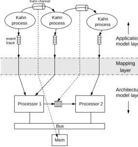
We divide Sesame into three layers: application, mapping, and architecture. All three follow the same component based design. Each layer has a set of components which can be instantiated and connected using YML files. This allows for reuse of code and the
model layer Kahn channel Mapping layer model layer Application Architecture event trace process process Processor 1 Bus Kahn Kahn Kahn Processor 2 process Mem
Figure 1: The three layers within Sesame: the application model layer, the architecture model layer, and the mapping layer.
flexibility to easily manipulate the model based on performance results as dictated by the Y-Chart methodology. The layered infras-tructure of Sesame is shown in Figure 1. In the remainder of this paper, each of the layers will be discussed in more detail.
3.
Y-CHART MODELING LANGUAGE (YML)
Implementing the Y-chart methodology requires a software sys-tem in which designers can quickly create and change simulation models. Sesame was developed to facilitate such rapid construction through the use of libraries of pre-built simulation components. In order to enable quick modification a flexible description format for the interconnection of these simulation components is required.
Research into the glue or structure of the simulation models, yielded a number of requirements. First, structural descriptions should be simple keeping features at a minimum. Second, struc-tural descriptions must support hierarchy such that complex mod-els may be viewed and used as easily as basic components. Third, we required support for the simplification of repetitive model struc-tures. For example, a large lattice of switches in a network should not require a structural description directly proportional in size to the number of nodes in the network. Finally, to maintain flexibility, changes in model structure should not require changes to modeling components.
YML, or Y-Chart Modeling Language, is based on XML. Using XML was attractive because of its simplicity, flexibility, and wide programming language support. XML files naturally describe trees so it is easy to support hierarchy. The remainder of this section is an overview of YML which should demonstrate its simplicity and ability to reduce repetitive structures. A working knowledge of XML is assumed. For information about XML see [4].
YML describes simulation models as directed graphs. The basic elements of YML arelink,node,network,property, and
doc. YML containing only these elements is called flat YML. In addition, the elementsscriptandsetwere added to simplify description of complicated structures. The extended (i.e., non-flat) YML can be translated to flat YML by running it through our YML preprocessor. Each of these YML elements is described below.
node
Node elements represent components within a simulation model. In Sesame these components are application model processes or architecture model components. From YML’s perspective it does not matter what the node represents. It is up to the simulator to interpret the meaning. Node elements require anameattribute and optionally aclassattribute. Names must be unique in a network and serve as the node’s identifier. Theclassattribute is used by simulators to designate the node type. For example in our applica-tion simulator, theclassattribute defines a node to be a C, C++, or Java process.
port
Port elements provide connection points for nodes and networks. They require both a nameand dir or direction attribute. Port names must be unique within a node or network. Thedirattribute can contain the valuesin, out, orboth. If it is omitted, then
bothis assumed.
link
Link elements connect ports. They require object1, port1,
object2, and port2attributes. Object attributes identify the name of a node or subnetwork in the current network. The special keywordthiscan be used to specify the current network itself. The attributesobject1andobject2can never both contain the valuethis. This requirement removes the possibility of link cy-cles. Port attributes name the port of the specified object to which the link is connected.
network
Network elements encapsulate graphs of nodes and links, and may contain subnetworks which provide hierarchy in model descrip-tions. Network elements require anameand optionally aclass
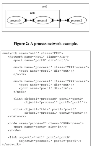
attribute. These attributes are used in the same manner as in node elements. The YML fragment shown in Figure 3 illustrates the aforementioned YML elements as it describes the process network depicted in Figure 2.
property
Property elements add information to YML objects. They gener-ally are specific to a simulator. A port, for example, may have a
typeproperty which designates the datatype used for communi-cation. Property elements require a nameandvalue attribute. Some example properties follow.
<property name="operation:add" value="0"/> <property name="operation:sub" value="1"/> <property name="input" value="input.dat"/> <property name="position" value="54,72"/>
This ends the flat-YML elements which are the basic building blocks of YML. The next two, more complicated, elements were introduced to reduce the size and increase the flexibility of YML descriptions.
script
Thescriptelement may be used to create dynamic YML. Cur-rently, Perl is supported as a scripting language, but any scripting language for which a YML Interpreter interface has been written can be used. Thescriptelement takes no attributes. The text within ascriptelement will be processed by the script inter-preter in the order it appears in the YML file. YML attributes in
name,class, orvalueelements that begin with a ’$’ are eval-uated as variables within the current context of the interpreter. At
process0 process1 process2 net1
net0
Figure 2: A process network example.
<network name="net0" class="KPN"> <network name="net1" class="KPN">
<port name="port0" dir="out"/>
<node name="process0" class="CPPProcess"> <port name="port0" dir="out"/>
</node>
<node name="process1" class="CPPProcess"> <port name="port0" dir="out"/>
<port name="port1" dir="in"/> </node>
<link object1="process0" port1="port0" object2="process1" port2="port1"/> <link object1="this" port1="port0"
object2="process1" port2="port0"/> </network>
<node name="process2" class="CPPProcess"> <port name="port0" dir="in"/>
</node>
<link object1="net1" port1="port0" object2="process2" port2="port0"/> </network>
Figure 3: YML description of process network in Figure 2.
this point we do not have a good method for providing scope within Perl so users must be aware that all variables are global. This can be especially tricky when including external entities which contain a script as it is not immediately obvious which variables are mod-ified by the included entity. An example is given together with the
setexample below.
set
Set elements further simplify the description of complex network structures by providing a for-loop like construct for the definition of YML structures. Thesetelement requires three attributesinit,
cond, andloop whose values are interpreted as script. init
is evaluated once at the beginning of the set processing. cond
is evaluated at the beginning of every iteration of set processing. The value ofcondis interpreted as a boolean. When it is false or 0 set processing stops. loopis evaluated once at the end of each iteration. When the following example YML is processed, five nodes named ’node0’ through ’node4’ will be created, each with a port named ’port0’.
<set init="$i = 0" cond="$i < 5" loop="$i++">
<script>
$nodename="node$i"; </script>
<node name="$nodename" class=""> <port name="port0" dir="out"/> </node>
</set>
3.1
Additional features
YML also benefits fully from the underlying XML language. Using XML parameter entities, YML libraries can be created. With library support and network hierarchy, model component and model component descriptions can be reused. In combination with the scripting feature, external entities can act as templates for complex structures. In Section 5, we describe how such templates are of great importance to flexible architectural modeling.
YML is a general purpose model description language and can be easily interfaced to any existing simulation tool either by trans-lating YML to native description languages or by a direct interface to a simulator’s internal data structures. Direct interfacing can be achieved using existing XML parsers alone or with assistance from YML programming interfaces.
4.
THE APPLICATION LAYER
We model application behavior using Kahn process networks (KPNs), because they expose application parallelism, make com-munication explicit, and execute deterministicly [9]. It was previ-ously shown in Section 3 how process networks are described in YML. To execute Kahn application models, we implemented (in C++) a runtime system called PNRunner or Process Network Run-ner. This system does not directly name Kahn because it has been designed to allow for the addition of new interconnection classes that implement rules of other process network models which we may wish to support in the future. PNRunner reads a YML process network description and executes the described application model. The core of PNRunner is not concerned with how, where, or in what language processes are run. This is abstracted away through pro-cess loader classes. Propro-cesses may consist of C, C++, Java code, or even run on a remote machine. PNRunner also makes no as-sumptions about the type of data communicated between processes. From the internal view of PNRunner, communications consist of blocks of byte data. It is up to specific process loaders and the processes themselves to interpret the data. Theclassattribute of YML node elements tells PNRunner which process loader to use.
Currently, our main process loader is a C++ class loader which supports part of the YAPI interface [7]. YAPI was developed at Philips Research for application modeling with KPNs. YAPI de-scribes KPNs completely in C++ and therefore specifies the net-work structure implicit in the source code. It also provides ap-plications with threading support and inter-process communication primitives. YAPI’s implicit description of process network struc-ture is redundant when using YML and therefore not supported in PNRunner. Sesame includes tools which ease conversion of YAPI applications to PNRunner applications.
Our C++ process loader recognizes a few special YML proper-ties. Most importantly, thelibraryandclassproperties tell the loader which shared library contains the process code and the name of the class in that library which implements the process. In support of the YAPI interface, which passes process parameters via the process constructor, we have two additional properties, namely
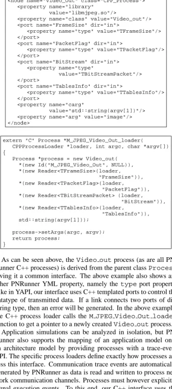
cargandarg. carg’s are constructor arguments andarg’s are general arguments which can either be used in the constructor ar-guments or accessed by the process directly. arg’s are passed at runtime unlikecarg’s which are fixed at compile time. Process classes are loaded via a generated stub. We have a separate tool to generate this stub code from YML descriptions. The following is a YML process description of a Video-Out application model process which originates from a M(otion)-JPEG application we studied in [15]. The corresponding auto-generated stub code follows.
<node name="Video_Out" class="CPP_Process"> <property name="library"
value="libmjpeg.so"/>
<property name="class" value="Video_out"/> <port name="FrameSize" dir="in">
<property name="type" value="TFrameSize"/> </port>
<port name="PacketFlag" dir="in">
<property name="type" value="TPacketFlag"/> </port>
<port name="BitStream" dir="in"> <property name="type"
value="TBitStreamPacket"/> </port>
<port name="TablesInfo" dir="in">
<property name="type" value="TTablesInfo"/> </port>
<property name="carg"
value="std::string(argv[1])"/> <property name="arg" value="image"/> </node>
extern "C" Process *M_JPEG_Video_Out_loader( CPPProcessLoader *loader, int argc, char *argv[]) {
Process *process = new Video_out( *(new Id("M_JPEG_Video_Out", NULL)), *(new Reader<TFrameSize>(loader,
"FrameSize")), *(new Reader<TPacketFlag>(loader,
"PacketFlag")), *(new Reader<TBitStreamPacket> (loader,
"BitStream")), *(new Reader<TTablesInfo>(loader, "TablesInfo")), std::string(argv[1])); process->setArgs(argc, argv); return process; }
As can be seen above, theVideo outprocess (as are all PN-Runner C++ processes) is derived from the parent classProcess
giving it a common interface. The above example also shows an-other PNRunner YML property, namely thetypeport property. Like in YAPI, our interface uses C++ templated ports to control the datatype of transmitted data. If a link connects two ports of dif-fering type, then an error will be generated. In the above example, the C++ process loader calls theM JPEG Video Out loader
function to get a pointer to a newly createdVideo outprocess. Application simulations can be analyzed in isolation, but PN-Runner also supports the mapping of an application model onto an architecture model by providing processes with a trace-event API. The specific process loaders define exactly how processes ac-cess this interface. Communication trace events are automatically generated by PNRunner as data is read and written to process net-work communication channels. Processes must however explicitly signal execution events. To this end, our C++ interface uses the YAPI approach. Running processes can emit execution trace events by calling the functionexecute(char *)and passing a string representing the execution event. Currently, PNRunner can out-put trace-event streams to files which, in UNIX systems, may be special files such as named pipes. More output options, such as a shared memory interface, will be considered as future work.
5.
THE ARCHITECTURE LAYER
The Sesame architecture models, which simulate the timing con-sequences of the events generated by an application model, are im-plemented in the Pearl1 discrete-event simulation language [13]. This is a small but powerful object-based language which provides
1
Not to be confused with Perl the scripting language
easy construction of (abstract) architecture models and fast simu-lation. It has a C-like syntax with a few additional primitives for simulation purposes. Architectures are modeled as communicating components (i.e., Pearl objects). Communication between com-ponents is performed using the special Pearl primitives ’!’ (syn-chronous communication) and ’!!’ (asyn(syn-chronous communication). The Pearl runtime system accounts for simulated time implicitly as components block for communication events or explicitly as they model computation with theblocktprimitive which blocks on the simulation clock.
To illustrate some of Pearl’s primitives and to demonstrate the ease of modeling in Pearl, Figure 4 shows the code of a bus model. This model was used in a study in which we mapped the aforemen-tioned M-JPEG application model onto a shared-memory multi-processor architecture model [15]. The model simulates bus trans-actions at the granularity of message transfers of abstract data types. As Pearl is an object-based language and architecture components are modeled by objects, the code shown in Figure 4 embodies the class of bus objects.
The bus object has two object variables,memandsetup. These variables are initialized at the beginning of the simulation, and more specifically, at the instantiation of a bus object. Themem
variable references the memory object that is connected to the bus, while the setup time of a connection on the bus is specified by
setup. A bus object has two functions:loadandstore. The
storefunction is not shown here since it is identical to theload
function. The bus object uses theblockt()primitive to wait for
setuptime units in order to account for the connection setup la-tency. The statement “mem ! load(nbytes, address)” calls theloadfunction of the memory objectmemby sending it a synchronous message. Since it is synchronous the bus has to wait until the memory has explicitly returned a reply message. The latter is done by thereply()primitive. In our example, the syn-chronous message passing also causes the virtual clock to advance in time, because the memory object accounts for the time it takes to retrieve the requested data before replying to the bus. After having received a reply from the memory object, the bus itself executes a
reply()to return control to one of the processor objects (which are connected to the bus object) that has called theloadfunction. At the bottom of Figure 4 is the main loop of the object which does nothing until either theloadorstorefunction is called (by one of the processor objects). We note that this bus model does not explicitly model bus arbitration. Instead, it uses Pearl’s internal scheduling, which applies a FCFS strategy to incoming function
class bus
mem : memory
setup : integer
load : (nbytes:integer, address:integer)->void {
blockt( setup );
mem ! load(nbytes, address); reply();
}
// [ store function is omitted ] {
while(true) { block(load, store); };
}
calls for the bus object. Nevertheless, an arbiter component which implements other strategies than FCFS can be added to the model with relative ease.
The Pearl environment also provides a basic framework for post-mortem analysis of the simulation results. To this end, it keeps track of five different types of statistical information: utilization (idle/busy times of objects), contention (busy objects with pend-ing messages), profilpend-ing (time spent in object functions), call graph analysis (critical path analysis), and average bandwidth between objects. In addition, Pearl provides run-time visualization features which aid the user in pinpointing performance problems, such as resource contention, during simulation.
Pearl is an excellent example of how an existing simulator can be integrated into Sesame via YML. Pearl uses its own language for describing architecture component interconnections. One inte-gration option would have been to create a translator from YML to Pearl’s native structure description language. But since the source code was readily available we choose to interface the Pearl run-time’s internal data structures directly to YML and replaced Pearl’s old structure descriptions with YML. This gives Pearl a lot of ad-ditional power. Using scripting we have, for example, described generic architecture models of crossbar and omega switches which can be scaled to any size using a simple parameter. Another ex-ample of the power of YML can be seen in a study we conducted on refinement of architecture processor models for modeling intra-task parallelism [16]. To this end, a processor model was divided into several functional units and a control unit. For this refinement, we simply made one template of the refined processor and used instances of it in a parallel architecture.
6.
THE MAPPING LAYER
The mapping layer (see Figure 1) maps the event traces gener-ated by the Kahn processes in an application model onto the re-sources in the architecture model. In addition, it maps the Kahn communication channels onto communication resources at the ar-chitecture level. For example, in Figure 1, one Kahn channel is mapped onto a point-to-point FIFO channel between processors 1 and 2, while the other Kahn channel is mapped onto a buffer in shared memory. The mapping of Kahn processes and channels onto components in the architecture model is described in YML and is thus freely adjustable.
As can be seen from Figure 1, it is possible to map multiple Kahn processes onto a single architecture component (e.g., in the case of a programmable component). Such mappings require the events from the event traces that are mapped onto the same architecture resource to be scheduled. This scheduling is also performed by the mapping layer. A detailed explanation of how this is done is beyond the scope of this paper. The interested reader is referred to [15, 16] for more information on Sesame’s mapping layer.
7.
RELATED WORK
There are a number of exploration environments, such as VCC [1], Polis [3] and eArchitect [2], that facilitate flexible system-level design space exploration by providing support for mapping a be-havioral application specification to an architecture specification. Within the Sesame project, which builds upon the ground-laying work of Spade [12], we try to push the separation of modeling application behavior and modeling architectural constraints at the system level to even greater extents. To this end, we apply trace-driven co-simulation of application and architecture models. As was shown in [15], this leads to efficient exploration of different design alternatives while also yielding a high degree of reusability.
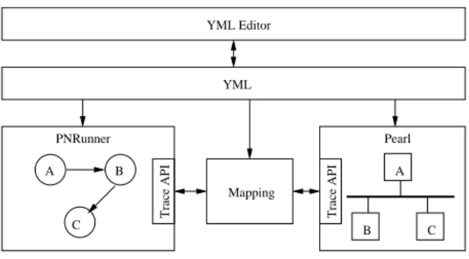
A B C Trace API B A C Trace API Pearl YML Editor PNRunner Mapping YML
Figure 5: Overview of Sesame software.
Additional, there are a multitude of projects involved in applica-tion modeling. The Ptolemy project [5] implements many types of application models including Kahn process networks. In [6] specialized Kahn process networks called MPPNs (multi-periodic process networks) are used to model applications and the synchro-nizations between communicating processes. In Sesame we sep-arate application and synchronization models. Synchronizations are modeled in the mapping layer [15]. We believe this separa-tion makes the applicasepara-tion model more reusable, because it does not depend on architectural details such as buffer sizes.
In the area of model structure description, MOML [11] of the Ptolemy project takes an approach similar to YML by describ-ing models as graphs usdescrib-ing XML trees. However, MOML and YML differ in a number of aspects. MOML targets general appli-cation simulation whereas YML specifically aims for the Y-Chart methodology. This will be more apparent with YML’s next release which will provide direct support for the description of applica-tion model to architecture model mappings. YML stresses simple model descriptions including the succinct description of repetitive structures and therefore provides dynamic scripting features not found in MOML. MOML also delegates its inter-process commu-nications throughrelation entities(a form of the media-tor design pattern) to better support the heterogeneous application models (e.g. mixing Kahn and state machines in one model) of the Ptolemy project. YML connects processes directly. In Sesame a communication mediator such as therelation entitywould only clutter model descriptions without gain, because we use only homogeneous application models (KPNs).
8.
DISCUSSION & FUTURE WORK
Figure 5 shows an overview of the Sesame software system. The simulation development environment is not entirely complete. We plan several new features which will make it easier to use and ex-pand functionality. For example, a graphical editor which will low the user to view and edit YML files as graphs of nodes is al-ready underway.
One of the trickiest tasks we have found in simulation develop-ment with the current Sesame system is mapping the application traces to the architecture components correctly. In theory, this is a rather simple problem, but in practice it is a cumbersome task as it requires that sometimes large numbers of port, process, and hard-ware component identifiers match up correctly in the event traces. Future enhancements to YML will remove this problem via a YML mapping description. In addition, this mapping description will be used to automatically generate the required mapping layer for a particular system simulation. The user’s task will then be reduced from manually creating the mapping layer to simply writing a YML
mapping description.
As a practical example of Sesame’s effectiveness, we performed a number of case studies. In [15], we studied an M-JPEG applica-tion. Here we conducted experiments with a shared-memory multi-processor architecture model. For this architecture, we evaluated different hardware-software partitionings, application to architec-ture mappings, processor speeds, and interconnect strucarchitec-tures: bus, crossbar, and omega networks. With the Sesame software system, all this work including the application and architecture modeling, took less than one person-month.
Moreover, in [16], we studied different instances of the well-known QR decomposition application. For this case study, we used QR application models that were also translated into VHDL [8]. This gave us the unique opportunity to compare our simulated per-formance measures to a real hardware implementation on an FPGA. The five different instances of the QR application we studied each expose a different degree of task parallelism. Our initial abstract architecture model yielded performance estimates that were on av-erage 36% off with respect to the FPGA implementation. Follow-ing the Y-Chart design methodology, we refined our processor ar-chitecture model into several functional units and a control unit to better represent the FPGA implementation. As a result, we were able to come within 3.5% average case and 4.7% worst case of the FPGA performance results. This was done with less than 400 lines of Pearl code and around 400 lines of YML to describe both archi-tecture and application models. It took Sesame about 16 seconds on a 333Mhz Sun Ultra 10 to perform the architecture simulations for all five application model instances in a batch.
9.
CONCLUSION
With increasingly heterogeneous architectures and larger num-bers of applications to support, embedded-systems tools like Sesame have become necessary to manage the complexity of design space exploration. With the Sesame software system we have created an embedded system co-simulation environment enabling developers to follow the Y-Chart design methodology. Changes can be made and the performance results evaluated quickly giving the designer more freedom to explore and discover an optimum design.
In this paper we have described the Sesame software system and demonstrated its effectiveness in modeling and simulating hetero-geneous embedded multimedia system. We will continue to use Sesame as a vehicle for future research and to make this tool avail-able for embedded system designers and researchers in the field. See http://sesamesim.sourceforge.net/ for the most up-to-date in-formation regarding the Sesame project.
Acknowledgments
This research is supported by PROGRESS, the embedded systems research program of the Dutch organization for Scientific Research NWO, the Dutch Ministry of Economic Affairs and the Technology Foundation STW. We thank Frank Terpstra and Simon Polstra for their work on YML and PNRunner.
10.
REFERENCES
[1] Cadence Design Systems, Inc., http://www.cadence.com/. [2] Innoveda Inc., http://www.innoveda.com/.
[3] F. Balarin, E. Sentovich, M. Chiodo, P. Giusto, H. Hsieh, B. Tabbara, A. Jurecska, L. Lavagno, C. Passerone, K. Suzuki, and A. Sangiovanni-Vincentelli.
Hardware-Software Co-design of Embedded Systems – The POLIS approach. Kluwer Academic Publishers, 1997.
[4] T. Bray, J. Paoli, C. M. Sperberg-McQueen, and E. Maler.
Extensible Markup Language (XML) 1.0 Second Edition,
October 2000.
[5] J. Buck, S. Ha, E. A. Lee, and D. G. Messerschmitt. Ptolemy: A framework for simulating and prototyping heterogeneous systems. Int. Journal of Computer Simulation, 4:155–182, Apr. 1994.
[6] A. Cohen, D. Genius, A. Kortebi, Z. Chamski, M. Duranton, and P. Feautrier. Multi-periodic process networks:
Prototyping and verifying stream-processing systems. In
Proc. of EuroPar’02, Aug. 2002.
[7] E. A. de Kock, G. Essink, W. J. M. Smits, P. van der Wolf, J. Y. Brunel, W. M. Kruijtzer, P. Lieverse, and K. A. Vissers. Yapi: Application modeling for signal processing systems. In
Proc. of the Design Automation Conference, pages 402–405,
June 2000.
[8] T. Harris, R. Walke, B. Kienhuis, and E. Deprettere. Compilation from matlab to process networks realized in fpga. In Proc. of the 35 Asilomar conference on Signals,
Systems, and Computers, Nov. 2001.
[9] G. Kahn. The semantics of a simple language for parallel programming. In Proc. of the IFIP Congress 74, 1974. [10] B. Kienhuis, E. F. Deprettere, K. A. Vissers, and P. van der
Wolf. An approach for quantitative analysis of
application-specific dataflow architectures. In Proc. of the
Int. Conf. on Application-specific Systems, Architectures and Processors, July 1997.
[11] E. A. Lee and S. Neuendorffer. MoML - a Modeling Markup Language in XML, version 0.4. Technical Report UCB/ERL M00/8, Electronics Research Lab, University of California, Berkeley, March 2000.
[12] P. Lieverse, P. van der Wolf, E. F. Deprettere, and K. A. Vissers. A methodology for architecture exploration of heterogeneous signal processing systems. Journal of VLSI
Signal Processing for Signal, Image and Video Technology,
29(3):197–207, Nov. 2001. Special issue on SiPS’99. [13] H. Muller. Simulating computer architectures. PhD thesis,
Dept. of Computer Science, Univ. of Amsterdam, Feb. 1993. [14] A. D. Pimentel, P. Lieverse, P. van der Wolf, L. O.
Hertzberger, and E. F. Deprettere. Exploring embedded-systems architectures with Artemis. IEEE
Computer, 34(11):57–63, Nov. 2001.
[15] A. D. Pimentel, S. Polstra, F. P. Terpstra, A. W. van Halderen, J. E. Coffland, and L. O. Hertzberger. Towards efficient design space exploration of heterogeneous embedded media systems. In Embedded Processor Design
Challenges: Systems, Architectures, MOdeling, and Simulation, pages 57–73. Springer, LNCS 2268, 2002.
[16] A. D. Pimentel, F. P. Terpstra, S. Polstra, and J. E. Coffland. Modeling of intra-task parallelism in Sesame. In Proc. of the
2nd Int. Workshop on Systems, Architectures, MOdeling, and Simulation (SAMOS-II), pages 1–16, July 2002.