1 | P a g e
LASER COATING OF TITANIUM CARBIDE ON
STAINLESS STEEL SUBSTRATE
A thesis Submitted by
CHOPPA KALYAN (109ME0604)
In partial fulfillment of the requirements For the award of the degree of
BACHELOR OF TECHNOLOGY
in
MECHANICAL ENGINEERING
Department of Mechanical Engineering
National Institute of Technology Rourkela
Orissa -769008, India
May 2013
2 | P a g e
CERTIFICATE
This is to certify that this report entitled, “LASER COATING OF TITANIUM CARBIDE ON STAINLESS STEEL SUBSTRATE” submitted by CHOPPA KALYAN in partial fulfillment of the requirements of Bachelor of Technology degree in Mechanical
engineering is a bonafide thesis work done by them under my supervision during the
academic year 2012-2013, in the Department of Mechanical Engineering, National Institute of Technology Rourkela, India.
To the best of my knowledge, the matter embodied in this report has not been submitted to any other university/institute for the award of any degree or diploma
Date:
Prof. M.Masanta
Department of Mechanical Engineering (Research Guide)
3 | P a g e
ACKNOWLWDGEMENT
We would like to give our deepest appreciation and gratitude to Prof. M. Masanta, for his invaluable guidance, constructive criticism and encouragement during the course of this project. Grateful acknowledgement is made to all the staff and faculty members of Mechanical Engineering Department, National Institute of Technology, Rourkela for their encouragement. I would also like to extend my sincere thanks to my group-mate, post graduate student Ms. K. Ushasri for her help. In spite of numerous citations above, the author accepts full responsibility for the content that follows. I also wish to express my deep sense of gratitude to Dr.K.P.Maity, HOD, Mechanical Engineering, N.I.T. Rourkela for giving us an opportunity to work on this project and valuable departmental facilities. We would also like to thank all the staff members of Mechanical Engineering Dept., NITR and everyone who in some way or the other has provided us valuable guidance, suggestion and help for this project.
Date: Choppakalyan(109ME0604)
B.Tech,
Mechanical Engineering,
4 | P a g e
ABSTRACT
Laser coating is an advanced material processing technology that has potential to deposit various materials locally on highly non-planar and complex surfaces. It can be used to refurbish or improve corrosion, wear and other surface related properties of the components (base metal). Surface hardness, wear resistance and corrosion resistance are the main properties, we consider in this study. In present study, a pulsed Nd:Yag laser will be used to deposit TiC on the base metal (stainless steel). Thus produced laser coating samples will be subjected to various mechanical (hardness, wear resistance) and metallurgical (microstructure and composition by SEM and XRD) analyses by changing different laser coating parameters such as laser power, laser scan speeds etc.
KEYWORDS: TiC coating, Nd:Yag laser, SEM (scanning electron microscope), XRD (X-ray diffractometer), AISI 304 stainless steel .
5 | P a g e
TABLE OF CONTENTS
TITLE PAGE NO.
CERTIFICATE 2 ACKNOWLWDGEMENT 3 ABSTRACT 4 TABLE OF CONTENTS 5 LIST OF TABLES 7 LIST OF FIGURES 8 LIST OF GRAPHS 9 CHAPTER 1: INTRODUCTION 1.1 Coating 10
1.2 Different Coating processes 10
1.3 Laser coating 11
1.4 Advantages 12
CHAPTER 2: LITERATURE REVIEWAND OBJECTIVE OF WORK
2.1 General 13-16
2.2 Literature review table 17
2.3 objective of present work 18
6 | P a g e
TITLE PAGE NO.
CHAPTER 3: EXPERIMENTAL PLANNING AND PROCEDURE
3.1 Experimental procedure. 20
3.2 Physical properties of TiC 21
3.3 Chemical composition of AISI 304 stainless steel 21
3.4 Different laser processing parameters for trial experiments 21
3.5 Different laser processing parameters for laser coating of AISI 304 steel 25 CHAPTER 4: RESULTS AND DISCUSSIONS
4.1 Micro hardness analysis 27
4.2 X-ray diffraction 29
4.3 SEM (scanning electron microscope) micrograph 31
CHAPTER 5: CONCLUSION
5.1 Conclusions 33
7 | P a g e
LIST OF TABLES
TITLE PAGE NO.
Table 1: Literature survey 17
Table 2: Chemical composition of AISI 304 stainless steel 21
Table 3: Different laser processing parameters for trial experiments 21
Table 4: Different laser processing parameters for laser coating of AISI 304 steel 25
8 | P a g e
LIST OF FIGURES
TITLE PAGE NO.
Fig. 1 :Schematic of laser coating process 20
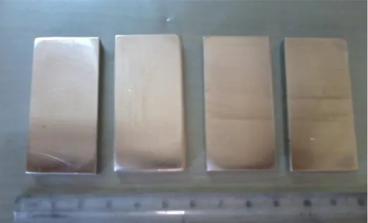
Fig. 2: AISI 304 Steel samples prior to coating. 22
Fig. 3: AISI 304 Steel samples after preplacing of TiC powder 22
Fig. 4: Nd-Yag pulsed laser experimental setup for development of coating 23
Fig. 5: Steel sample-1 after coating. 24
Fig. 6: Steel sample-2 after coating. 25
Fig 7: After coated sample of AISI 304 steel 26
Fig. 8: X-Ray Diffractometer 29
Fig. 9 : XRD pattern for coating processed with laser power 1.2 kW, frequency 15 Hz and scan speed 8 mm/s 30 Fig. 10: XRD pattern for coating processed with laser power 1.2 kW, frequency 18 Hz and
scan speed 4 mm/s 31 Fig. 11: SEM micrograph at the cross section for TiC coating on AISI 304 steelprocessed
with a laser power 1.2 kW, frequency 15 Hz and scan speed 8 mm/s 31 Fig. 12: SEM micrograph at the cross section for TiC coating on AISI 304 steel processed
9 | P a g e
LIST OF GRAPHS
TITLE PAGE NO:
Graph 1: micro hardness vs experiment 27 Graph 2: Micro hardness vs Scan speed at
constant peak power (1.2 KW) and frequency (15 Hz) 28 Graph 3: Micro hardness vs Scan speed at
10 | P a g e CHAPTER-1
INTRODUCTION:
Engineering components need to have superior surface properties in corrosive and erosive environments. Due to this requirement, composite coatings have been studied and developed over the past few decades. Composite coatings generally include hard particles such as carbides or oxides distributed in matrixes such as polymers, ceramics or metal. Metal matrix composites (MMC) have advantages (depending on matrix property) such as high wear, corrosion resistance and ability to work at high temperature producing the matrix is a high melting point metal such as Ni and Co. WC-Ni, WC-Co and TiC-Fe are examples of metal matrix composites. These advanced materials have a metal matrix in which non-metallic fibers, particles, or whiskers are dispersed. For use in tribological applications, metal-matrix composites must be able to support a load without distortion, deformation, or fracture during performance and to maintain controlled friction and wear over long periods without seizure under working conditions.
1.1 Coating
A coating is a covering that is applied to the surface of an object, usually referred to as the substrate. In many cases coatings are applied to improve surface properties of the substrate, such as appearance, adhesion, wetability, corrosion resistance, wear resistance, and scratch resistance. Some new coatings formulated using nanotechnology promise to create long-term surface protection [1]. In other cases, in particular in printing processes and semiconductor device fabrication (where the substrate is a wafer), the coating forms an essential part of the finished product.
1.2 Different Coating processes
Chemical vapor deposition
o Metal organic vapour phase epitaxy.
o Electrostatic spray assisted vapour deposition (ESAVD).
11 | P a g e
o Cathodic arc deposition
o Electron beam physical vapour deposition (EBPVD) o Ion plating
o Ion beam assisted deposition (IBAD) o Magnetron sputtering
o Pulsed laser deposition o Sputter deposition o Vacuum deposition
o Vacuum evaporation, evaporation (deposition)
Chemical and electrochemical techniques
Anodizing
Chromate conversion coating
Plasma electrolytic oxidation
Ion beam mixing
Plating
o Electro less plating o Electroplating
Sol-gel
Spraying
High velocity oxygen fuel (HVOF) Plasma spraying
Thermal spraying
Laser coating
1.3 Laser coating
Laser coating is an advanced material processing technology that produces an extremely dense, crack-free and non-porous structure with an excellent metallurgical bond to the base
12 | P a g e
material. It is known for very low dilution and low heat input to the component. For different applications, laser coating offers a wide range of possible coating materials. Laser coating of cobalt based hard alloys (e.g. Stellite-6 and 21), nickel based super-alloys (e.g. Inconel 625), self-fluxing alloys (e.g. NiCrBSi) and stainless steels are widely used for various applications.
The advantages of laser coating include minimal heat input, less impact on substrate mechanical properties, and the ability to adapt to automation systems. The laser produces focused energy, there by melting the substrate and powder to deposit the clad. Process parameters play a crucial role in both clad quality and clad microstructure.
There are significant advantages of laser coating over standard or traditional weld cladding or hard facing.
1.4 Advantages
Best technique for coating any shape => increase life-time of wearing part by 6-7 years.
A lot of material flexibility (metal, ceramic, even polymer).
High cooling rate => fine microstructure.
Can produce denser coatings with little or no porosity, finer surface finishes, more consistent layer thicknesses, and more precise clad placement, than traditional thermal spray techniques.
Is inherently a low heat input process, resulting in low dilution, fine microstructures, small heat affected zones (HAZ), and low distortion.
In specific applications, laser cladding may restore parts to their original dimensions without secondary operations.
13 | P a g e CHAPTER-2
LITERATURE REVIEW AND OBJECTIVE OF WORK
2.1 General
Paul et al.[1] have used pulsed Nd:YAG laser to develop WC–Co coating on low carbon steel. The authors used laser power 1kW with a scan speed of 4-7mm/s. Produced laser cladding samples were subjected to various mechanical tests and metallurgical analyses. The results showed that fully dense and crack free clad surfaces of WC–Co with an excellent metallurgical bonding and low dilution were deposited. No melting of WC particles in the Co matrix was observed. The average micro-hardness at the clad surface was about 1350HV, while that at substrate was 200HV. The observed adhesion strength of the WC–Co cladding to the substrate was about 60MPa. The element distribution across the substrate/clad was fairly smooth. The dilution up to 0.2mm height in the clad layer was observed. The micro-hardness of 1250–1700 VHN was observed in the clad layer.
Agarwal et al.[2] have used a 2.5 kW continuous wave Nd:YAG laser (1.06 mm wavelength) equipped with a fiber optic beam delivery system for synthesis of TiB2 coatings on AISI 1010 steel by laser surface engineering (LSE) process. The authors used laser beam power of 1.5 kW and laser beam transverse speed of 33 mm/s. The wear resistance of TiB2
coated surface is found higher than AISI 1010 steel substrate. The authors also found wear resistance of the LSE TiB2 coating is even better than that of the PES (Pulse Electrode
Surfacing) deposited TiB2 coating. Coefficient of friction values for LSE coated TiB2 coating
(µ=0.6) is found lower than PES deposited TiB2 coating (µ=0.7). The authors also observed wear occurs in PES deposited TiB2 coating by brittle fracture and attrition type mechanisms
whereas mixed adhesive–abrasive wear in LSE deposited TiB2 coating occurs by localized
plastic deformation of the soft matrix phase Fe from a ‘‘composite’’ layer on the surface. Alemohammad et al.[3] have deposited a crack free Co-Ti on mild steel substrate by pre-placed laser cladding technique. A pulsed Nd:YAG laser with a nominal power of 1 kW and different laser scanning velocities (3.5-4.4 mm/s) were utilized, which resulted in different
14 | P a g e
rates of cooling during the formation of clad layers. The change in laser scanning velocity resulted in variations in the microstructural characteristics, as well as the hardness of the clad layer.
Corbin et al. [4] have used pulsed Nd: YAG laser and a 9MP-CL Sulzer Metco powder feeder for deposition of Fe-Al on Mild-steel. Laser power 350W and scan speed of 2mm/s have been used. The clad deposition rate, measured by clad height, increased with an increase in duty cycle of the laser, either through an increase in pulse duration or frequency, an increase in powder feed rate and decrease in substrate velocity. A simple analysis using concepts of an effective interaction time, energy and powder deposition density, all of which were determined by laser duty cycle, powder feed rate and substrate velocity, was developed. Taken together these three parameters allow a determination of the processing conditions that will give rise to a high quality Fe-Al clad on mild steel with a specified height.
McCAY et al.[5] have used 3 kW Nd :YAG laser at an overlap index of 2.5mm at 2000W and 1000, 1500, 2250 and 3000 mm/min for deposition of slurry comprised of chromium (44 wt %), nickel (22 wt %), silicon carbide (3 wt %) and tungsten carbide (8 wt %) powder on AISI 4340 steel. Also, the substantial dissociation of the original carbides (SiC and WC) into elemental silicon and tungsten supplemented the stabilization of ferrite and reduction in the hardness.
Emamian et al.[6] have studied the effect of laser cladding process parameters on TiC morphology. Two combined parameters, effective energy and powder deposition density, are used in order to study the effect of laser process parameters on TiC morphology. The authors also points out that, same combined laser parameters can produce different microstructures if individual parameters, such as laser power, are different. The most important feature controlling clad microstructure was the level of dilution by the substrate. All samples with a low level of dilution exhibited a high volume fraction of fine, spherical TiC while samples with high dilution exhibited a lower volume fraction of coarse TiC phases with a dendritic structure. The work points out that laser cladding conditions should be chosen to create a minimum amount of dilution just enough to bond the clad to the substrate. This will promote a partially solid melt pool and maintain a high volume fraction of TiC in the clad.
Ariely et al.[7] have produced an alloy surface of TiC in AISI 1045 steel by laser surface alloying using a CO2 laser of 2.5 kW maximum power. Optimal laser and powder feed
15 | P a g e
parameters were established. The microstructure was investigated metallographic ally. Alloying the surface with TiC significantly increases the surface-hardness relative to that of the bulk material, mainly due to presence of un-dissolved TiC particles. Some of the particles had partially melted during the passage through the laser beam and had re-solidified, forming small and fine dendrites. Phase identification by X-ray diffraction revealed the presence of α-Fe and α-Fe3C phases as well as stoichiometric amounts of TiC.
Ouyang et al. [8] found that the degree of wear depends mainly on the extent of de-bonding and removal of TiC particles. With increasing normal load, mild scratching with fine grooves, oxidative wear with a thin layer of Ni203 film, delamination wear with serious plastic deformation and regular scale-like features were observed on the worn surfaces of coatings corresponding to various wear conditions. The softening and local melting of worn surface layers caused by friction heat produces a crushed crystalline or amorphous structure. TIC reinforced coating possesses a much higher wear resistance than a single Ni-alloy coating. The degree of wear for composite coating depends primarily on the extent of de-bonding and removal of TiC particles. With increasing the normal load, mild scratching with fine grooves, oxidative wear with a thin Ni,O, film and delamination mechanism of material with a scale-like feature are observed on the worn surface corresponding to the increase of severity of wearing conditions.
Y.T. Pei et al.[9] have used a 2.5 kW continuous wave CO2 laser to produce a series of
single clad tracks without overlap under the processing conditions of 1800–2200 W laser power, 4–8 mm /s scanning speeds with 3 mm beam diameter. The clad layers consisted of TiC particles, g-Ni primary dendrites and interdendritic eutectics. Laser processing parameters have a considerable influence on the gradient distribution of TiC particles in the clad layers.
Axen et al.[10] have produced TiC-steel composite clad layers containing about 50 vol.% TiC on tool steel (90MnCrV8) using a 3.5 kW CO2 laser. After laser cladding, the hardness
and the volume fraction of retained austenite of the martensitic matrix were varied by heat treatments. Wear tests were carried out on the different composites using a laboratory tribometer in dry reciprocating sliding contact against SiC abrasive paper of different grit sizes. Incorporation of TiC particles enhanced the wear resistance up to about 6 times compare to the unreinforced steel after equal heat treatment.
16 | P a g e
Katipelli et al.[11] have employed a 2-kW continuous wave Nd:YAG laser equipped with a fiber optic beam delivery system for for deposition of TiC on Al 6061 alloy. With a laser beam spot dia of 3.5 mm and a 20% overlap between two consecutive laser tracks laser power of 1.8 kW and traverse speed of 120 cm/min have been used. The author observed that the developed coating is composite in nature with the microstructure consisting hard TiC particles reinforced in a matrix of Al–Ti mixture. The average surface roughness of the coating was found to be 13.5 mm. High hardness and wear resistant have been obtained in the coating which mainly highly influenced by the composite nature of the coating.
Kathuria et al. [12] modify the surface properties of various base materials with the varying percentage of metal carbide by laser cladding process using pulsed Nd:YAG laser. The laser beam was focused by a lens of focal length f=80 mm so as to produce a spot size of 300-1000 µm. results indicate that the laser cladding of chromium carbide cermet with 70 wt.% of metal carbide content exhibits higher hardness compared to the 50 wt.% of metal carbide content. However, crack formation in the later case reduced compared to the previous case. Successful laser cladding of titanium carbide cermet was produced with 30 wt.% of metal carbide content. The erosion test clearly indicates a low loss of weight when compared to the Stellite 6 coating.
Kadolkar et al.[13] have investigated the nature and magnitude of the residual stresses within laser-deposited titanium carbide (TiC) coatings on 2024 and 6061 aluminum (Al) alloys. They have used a 2-kW Rofin Sinar continuous wave Nd:YAG laser equipped with a fiber optic beam delivery system for deposition of TiC on 2024 and 6061 Al substrates. Macro and micro-stresses within the coatings were determined using an X-ray diffraction method. Owing to increased de-bonding between the coating and the substrate, the macro-stresses were found to be compressive and to decrease in magnitude with increasing processing speed. The micro-stresses in the TiC particulate and aluminum matrix phases within the coatings were found to be independent of the amount of de-bonding. The residual micro-stresses in the Al matrix of the coating were tensile, whereas those in the TiC particles were compressive.
As lot of research work has not been done on deposition of TiC on stainless steel(AISI 304) using Nd-Yag laser,we have choosen this study of deposition of TiC on stainless steel(AISI 304) using Nd-Yag laser coating process.
17 | P a g e
Sl.N
o YEAR AUTHOR Journal, vol. page
Theoretical/
Analytical/Experimental/statisti
cal Machine in use material
Experimental
Parameters Major findings
1 2003
S.F. Corbin *, E. Toyserkani ,
A.Khajepour A354 (2003) 48-57
Cladding of an Fe-aluminide coating on mild steel using pulsed laser assisted powder deposition
350-W pulsed
Nd: YAG laser and a 9MP-CL Sulzer Metco powder feeder.
Fe-Al on Mildsteel
laser power-350W , Scan speed-2mm/s
influence of laser beam characteristics such as laser beam spot size, substrate velocity, powder feed rate on clad height and clad dilution
2 2007 C.P. Paul ∗, H. Alemohammad, E. Toyserkani, A. Khajepour, S. Corbin A 464 (2007) 170–176 Cladding of WC–12 Co on low carbon steel using a pulsed Nd:YAG laser
1kW pulsed Nd:YAG laser was used.
WC12-Co on low
carbon steel scan speed-4-7mm/s
micro harness achieved-1350 HV. Effect of diff. Process parameters such as laser energy, pulse duration, frequency, scan velocity on surface appearance and clad quality.
3 2007 Hamidreza Alemohammad∗, Shahrzad Esmaeili, Ehsan Toyserkani A 456 (2007) 156–161
Deposition of Co–Ti alloy on mild steel substrate using laser cladding.
A pulsed Nd:YAG laser manufactured by LASAG and a nominal power of 1 kW was used.
Co-Ti on mild steel.
laser power-1kw , scan speed-3.5-4.4mm/s
micro harness achieved-240 HV . Different laser scanning velocities were utilized, which resulted in different rates of cooling during the formation of clad layers. The change in laser scanning velocity resulted in variations in the microstructural characteristics, as well as the hardness of the clad layer
4 2008 Baoshuai Du a,b,Anoop N. Samant a, Sameer R. Paital a, Narendra B. Dahotre a,* 255 (2008) 3188–3194
Pulsed laser synthesis of ceramic–metal composite coating on steel.
A JK 701 model pulsed Nd:YAG laser with average power of 400W(pulse duration: 0.5– 2 ms; repetition rate: 20 Hz) was used. TiB2+Al on AISI 1010 steel.
laser power-400w , scan speed- 84.7mm/s
Micro hardness achieved -900 HV.It is observed that coating with an optimum combination of hardness ( Hv 900) and surface roughness (Ra 6.1) possess minimum wear rate (0.113 mg/(min cm2)).
5 2000
Arvind Agarwal, Narendra B.
Dahotre. 240 (2000). 144–151
Comparative wear in titanium diboride coatings on steel using high energy density processes
A 2.5 kW Hobart HLP 3000 continuous wave Nd:YAG laser 1.06 µm wavelength. equipped with a fiber optic beam delivery system was used.
TiB2 on AISI
1010 steel. scan speed-33mm/s
The coefficient of friction values for LSE coated TiB2 coating ( µ=0.59), is lower than for PES deposited TiB2 coating ( µ=0.68).Wear occurs in PES deposited TiB coating by brittle fracture and attrition type failure mechanisms. Wear in LSE deposited TiB2 coating occurs by plastic deformation and gradual wear ( mixed adhesive-abrasive mode) of the soft matrix phase Fe from a ‘‘composite’’ layer on the surface.
18 | P a g e
2.3 Objective of the present work:
1. Development of hard TiC ceramic coating on AISI 304 steel substrate by laser processing of preplaced TiC powder using Nd:YAG pulsed laser.
2. Desired properties of the obtained coatings are analysed by SEM (scanning electron microscope), XRD (X-ray diffraction) technique and micro hardness measurements.
3. Effect of laser processing parameters i.e. laser power, pulsed frequency and scanning speeds on the developed coating has been analyzed.
19 | P a g e
2.4 SCHEDULE OF THE WORK
JULY AUG. SEPT. OCT NOV DEC JAN FEB MAR. APRIL MAY LITERATURE SURVEY MATERIAL SELECTION MATERIAL PURCHASE PLANNING OF EXPERIMENT LASER COATING EXPERIMENT MEASUREMENT AND RESULT ANALYSIS OF THE RESULT THESIS WRITING
20 | P a g e CHAPTER-3
EXPERIMENTAL PLANNING AND PROCEDURE:
3.1 Experimental procedure
The procedure can be divide into three stages: 1) Pre placing the power
In this stage TiC or TiB2 powder mixed in alcohol or acetone is sprayed or painted on the base metal. The powder precursor made of TiC or TiB2 suspended in alcohol or acetone .This powder precursor is sprayed over the steel (base metal). Average precursor thickness will be 100-150 micrometer. Sprayed surfaces will be dried for 1 hr prior to laser processing.
2) Laser Processing
In this stage Nd:Yag pulsed laser will be used for laser processing operation. First the laser parameters such as laser power, scan speed etc are properly set and Laser will be scanned over the pre placed powder surface which was obtained from the previous stage.
3) Measurement
Desired properties of the laser coated surface such as Hardness, wear, micro-structure are measured using different measuring instruments. Phase analysis will be done by XRD (X-ray diffraction technique).
21 | P a g e
3.2 Physical properties of TiC
Density - 4.93 gm/cc
melting point - 3067⁰C
modulus of elasticity - 439 GPa
coefficient of thermal expansion 8.15 – 9.45× . Table:2- 3.3 Chemical composition of AISI 304 stainless steel
Element Present
C Si Mn P S Ni Cr Mo Fe
Compostion(%) 0.067 0.0753 1.731 0.045 0.031 0.554 18.97 0.224 78.302 Firstly experiment was conducted on the steel to find out the limiting parameters on the laser machine such as Peak power, frequency, scan speed, Ton etc.
3.4 Different laser processing parameters for trial experiments:
Table 3:laser processing parameters for trial experiments Laser surface No. Spot dia (mm) Peak-power (Kw) Ton (ms) Frequency (Hz) Speed (mm/s) SAMPLE 2 1 1.5 1 12 15 10 2 2 6 15 10 3 1 12 10 10 4 1 12 15 8 5 3 12 5.5 2.5 6 4 12 4.2 2.5 7 3 12 5.5 5 8 3 12 5.5 10 SAMPLE 1 1 1.5 1 12 15 10 2 2 6 15 10 3 1 12 10 10 4 1 12 15 8 5 1 12 15 2.5 6 1 12 15 6 7 0.3 12 15 12 8 1 12 15 12 9 0.7 12 15 10 10 0.5 12 15 10
22 | P a g e
Average power = FREUENCY × Ton × Peak Power Where frequency is in pulse /sec
In the above experiment no 5,6,7,8 of sample 2 with the Peak-Power 3KW-4KW and scan speed of 2.5-5 mm/s gives a surface which is non uniform in nature and highly rough ,there is spattering of TiC by laser due to low speed and high power, therefore high Peak-Power and low scan speed is not suitable for coating of TiC using laser. We also observed experiment no 7,8,9,10 of sample 1 where peak-power is <1KW, there is a layer formation of TiC and this formed layer doesn’t integrate with the substrate surface which means the layer is peeled off easily. We also found that better coated surfaces are formed in the range of 1-2 KW peak-power and frequency 15Hz and at a lower speed.
Fig 2 AISI 304 Steel samples prior to coating
23 | P a g e
Fig 4. Nd-Yag pulsed laser experimental setup for development of coating
Nd:YAG (neodymium-doped yttrium aluminum garnet; Nd:Y3Al5O12) is a crystal that is
used as a lasing medium for solid-state lasers. The dopant, triply ionized neodymium, Nd(III), typically replaces a small fraction of the yttrium ions in the host crystal structure of the yttrium aluminium garnet (YAG), since the two ions are of similar size. It is the neodymium ion which proves the lasing activity in the crystal, in the same fashion as red chromium ion in ruby lasers. Generally the crystalline YAG host is doped with around 1% neodymium by atomic percent.
Nd:YAG lasers are optically pumped using a flashtube or laser diodes. These are one of the most common types of laser, and are used for many different applications. Nd:YAG lasers typically emit light with a wavelength of 1064 nm, in the infrared. Nd:YAG lasers operate in both pulsed and continuous mode. Pulsed Nd:YAG lasers are typically operated in the so called Q-switching mode: An optical switch is inserted in the laser cavity waiting for a maximum population inversion in the neodymium ions before it opens. Then the light wave can run through the cavity, depopulating the excited laser medium at maximum population
24 | P a g e
inversion. In this Q-switched mode, output powers of 250 megawatts and pulse durations of 10 to 25 nanoseconds have been achieved. The high-intensity pulses may be efficiently frequency doubled to generate laser light at 532 nm, or higher harmonics at 355 and 266 nm.
Nd:YAG absorbs mostly in the bands between 730–760 nm and 790–820 nm.At low current densities krypton flash-lamps have higher output in those bands than do the more common xenon lamps, which produce more light at around 900 nm. The former are therefore more efficient for pumping Nd:YAG lasers.
The amount of the neodymium dopant in the material varies according to its use. For continuous wave output, the doping is significantly lower than for pulsed lasers. The lightly doped CW rods can be optically distinguished by being less colored, almost white, while higher-doped rods are pink-purplish.
Nd:YAG lasers are also used in manufacturing for engraving, etching, or marking a variety of metals and plastics. They are extensively used in manufacturing for cutting and welding steel, semiconductors and various alloys. For automotive applications (cutting and welding steel) the power levels are typically 1–5 kW. Super alloy drilling (for gas turbine parts) typically uses pulsed Nd:YAG lasers (millisecond pulses, not Q-switched). Nd:YAG lasers are also employed to make subsurface markings in transparent materials such as glass or acrylic glass. Lasers of up to 400 W are used for selective laser melting of metals in additive layered manufacturing. In aerospace applications, they can be used to drill cooling holes for enhanced air flow/heat exhaust efficiency.
25 | P a g e
Fig 6: Steel sample-2 after coating (Trial experiments)
Samples which are coated with TiC using laser are shown in the figure 4 & 5.These samples are samples which are taken after TiC coating was done on them.
3.5 Different laser processing parameters for laser coating of AISI 304 steel:
Table 4: laser processing parameters for TiC coating of AISI 304 steel
Experiment no
peak
power(KW) Ton(ms) frequency(Hz) scan speed(mm/s)
1 1.2 9 15 4 2 1.2 9 15 6 3 1.2 9 15 8 4 1.2 9 15 10 5 1.2 9 18 4 6 1.2 9 18 6 7 1.2 9 18 8 8 1.2 9 18 10
Average power = FREUENCY × Ton × Peak Power Where frequency is in pulse /sec
Sample calculation:
Avg power for exp 1= 15 ×9×1.2 = 162W .
Here total of eight experiments are conducted on the samples. First four experiment we kept the peak power and Ton constant and varied scan speed,to find its effect on the coating formation on the base metaland the next 4 experiments ,we increased the power a bit,compared to the previous value , but kept it constant for the four experiments and also frequency is increased to 18 ,compared to previous 15 , but kept it constant for the four
26 | P a g e
experiments and we have varied speed like in the first case , to find out its effect on the nature of the coated surface formed on the base metal. Subsequently, different tests are carried out to find the type of coated surface formed on the base metal and its properties.
27 | P a g e CHAPTER-4
RESULTS AND DISCUSSIONS
4.1 Micro hardness analysis
Table 5: Micro hardness values obtained; all values in VHN* units
Test no Exp-1 Exp-2 Exp-3 Exp-4 Exp-5 Exp-6 Exp-8
1 1142 731 1096 1143 1125.8 1004.1 643.9 2 1066 528 1094 1344 890 1249 570.1 3 999 566 992 891 843.2 1361.6 579.4 4 1243 847 692 1422 787 1532.6 ---- 5 1370 747 1154 834 766.4 1241.8 --- 6 1030 804 1474 --- ---- 858.7 --- Average value 1141.6 703.8 1083.6 1126.8 882.4 1207.9 597.8
Micro hardness values for different experimental surfaces are calculated using Vickers Hardness tester and these values are tabulated as shown in the table 3. After the graph is plotted between experiment no and micro hardness values as shown.
Graph 1: micro hardness vs experiment no., (micro hardness values are in VHN)
1141.666667 703.8333333 1083.666667 1126.8 882.48 1207.966667 597.8 0 200 400 600 800 1000 1200 1400
Exp-1 Exp-2 Exp-3 Exp-4 Exp-5 Exp-6 Exp-8
Series1 Series2 Series3
28 | P a g e
In the above graph different values of the micro hardness of the corresponding experiments are plotted. These data or graphical representation shows that micro hardness value of the coated surfaces varies from 597.8 to 1207.967 VHN (Vickers Hardness Number).
4 6 8 10 0 500 1000 1500 Mi cro h ard ne ss H V
laser scan speed (mm/s) laser pulse frequency-15 Hz
Graph 2: Micro hardness vs laser scan speed at constant peak power (1.2 KW) and frequency (15 Hz) 4 6 8 10 0 500 1000 1500 Mi cro h ard ne ss H V
laser scan speed (mm/s) laser pulse frequency-18 Hz
Graph 3: Micro hardness vs laser scan speed at constant Peak power (1.2KW) and frequency (18Hz)
29 | P a g e
Experiments conducted at constant peak power of 1.2 KW and frequency of 15Hz and different laser scanning speeds. Micro hardness values of the coating surface formed with different laser scanning speeds have been plotted in graph 2. From this graph we have found that at peak power of 1.2KW and frequency of 15 Hz, micro hardness of the coated surfaces is almost the same, this implies that the micro hardness of the surface formed is independent of the laser scan-speed.
Here in the graph-3 experiments are conducted at constant peak power of 1.2 KW and frequency of 18Hz and effect of speed on the coating surface formed was analysed by micro hardness data. From this graph we have found that at higher frequency of 18 Hz, the micro hardness of the surface formed is highly dependent on the scan speed. As the graph 3 shows, at low speed 4 mm/s the micro hardness of the surface formed is not so high, but at little higher speed 6 mm/s the micro hardness is highly desired. With further increase of speed to 10 mm/s micro hardness of the surface formed are decreases. This implies that at higher frequency, to get a good coated surface, the scanning speed should be medium.
4.2
X-ray diffraction
:30 | P a g e
Following analysis can be done from XRD :
1) Phase determination- Identification of crystalline phases.
2) Quantitative phase analysis- Relative composition of mixed phases.
3) Calculation of lattice parameters-Structural variations under different conditions.
4) Analysis of crystallite size and strain- Estimation of size of crystalline domain and disorder.
5) Structure solution- Complete structure refinement of unknown phases. Experimental XRD data: 20 40 60 80 100 0 50 100 150 200 250 b b b b b a a a a a In te n si ty 2 Sample-3 (1.2kW, 8mm/s,15Hz) a=TiC b=AISI 304 steel
Fig 9: XRD pattern for coating processed with laser power 1.2 kW, frequency 15 Hz and scan speed 8 mm/s
The XRD patterns were analysed with the help of Phillip’s X’pert software. Here in the fig 9, which corresponds to the XRD pattern for experiment/sample 3 shows that two phases mainly TiC and AISI304 steel exists in the pattern , which confirm a TiC layer formed on the AISI 304 steel substrate.
31 | P a g e 20 40 60 80 100 0 50 100 150 200 250 b b b b b a a a a a In te n si ty 2 Sample-5 (1.2kW, 4mm/s,18Hz) a=TiC b=AISI 304 steel
Fig 10. XRD pattern for coating processed with laser power 1.2 kW, frequency 18 Hz and scan speed 4 mm/s
Fig 10, which corresponds to the XRD data for experiment/sample 3 also shows the existence of TiC layer on AISI304 steel.
4.3 SEM (scanning electron microscope) micrograph
Fig 11. SEM micrograph at the cross section for TiC coating on AISI 304 steel processed with with laser power 1.2 kW, frequency 15 Hz and scan speed 8 mm/s
32 | P a g e
Figure 11 shows that there is formation of TiC layer on the surface as shown in the figure, which integrated or dispersed with the base metal as we move from coating surface towards substrate or the base metal upto certain depth. This figure also shows that there is a uniform layer formation on the base metal.
Fig 12. - SEM micrograph at the cross section for TiC coating on AISI 304 steel processed with with laser power 1.2 kW, frequency 18 Hz and scan speed 4mm/s
Figure 12 shows that at high speed and high peak power ,there is non uniform TiC layer formation as shown in the figure and here TiC layer is non uniform and discontinuous in nature and there is integration of TiC with base metal is also there as shown in the right hand part of the figure.
33 | P a g e
CHAPTER 5
CONCLUSIONS
5.1 Conclusions:
1) A uniform layer of TiC coating has been formed by laser coating process on AISI 304 steel.
2) At peak power of 1.2KW and frequency of 15 Hz, the micro hardness of the surface formed is independent of the scan-speed.
3) At peak power of 1.2KW and at higher frequency of 18 Hz, the micro hardness of the surface formed is highly dependent on the scan speed and to get a good coated surface with high micro hardness, the scan speed should be medium.
4) At high speed and high peak power, TiC layer formed is non uniform and discontinuous in nature.
34 | P a g e References
1. Paul, C.P., Alemohammad, H., Toyserkani, E., Khajepour, A., Corbin, S., 2007, “Cladding of WC–12 Co on low carbon steel using a pulsed Nd:YAG laser” ,J. Materials Science and Engineering ,A 464,pp. 170–176.
2. Agarwal, A., Dahotre, N.B., 2000 ,“ Comparative wear in titanium diboride coatings on steel using high energy density processes”, J.Wear ,240pp. 144–151.
3. Hamidreza Alemohammad., Shahrzad Esmaeili., Ehsan Toyserkani., 2007 “Deposition of Co–Ti alloy on mild steel substrate using laser cladding”,J.Materials Science and Engineering ,A 456,pp. 156–161.
4. Corbin,S.F. , Toyserkani, E., Khajepour, A.,2003, “Cladding of an Fe-aluminide coating on mild steel using pulsed laser assisted powder deposition”,J.Materials Science and Engineering,A354, pp. 48-57.
5. McCAY, M. H., DAHOTRE,N. B., HOPKINS,J. A., McCAY, T. D.,1999, “The influence of metals and carbides during laser surface modification of low alloy steel”,journal of materials science ,34 ,pp-5789 – 5802.
6. Ali Emamian., Stephen Corbin ,F., Amir Khajepour .,2011, “The influence of combined laser parameters on in-situ formed TiC morphology
during laser
cladding
”,J.Surface & Coatings Technology ,206, pp.124–131.7. Ariely, S., Shen ,J., Bamberger, M., Dausiger , F., HugeF, H.,1991, “Surface and Coatings Technology”, 45 , pp.403-408.
8. Pei,Y.T., Lei, T.C., Zhou, Y., Ouyang J.H. ,1995, “Tribological behaviour of laser clad TiCp composite coating”,J. Wear ,185, pp. 167-172.
9. Pei, Y.T., Zuo, T.C.,1998, “Gradient microstructure in laser clad TiC-reinforced Ni-alloy composite coating”,J.Materials Science and Engineering ,A241, pp.259–263. 10. Axen, N., Zum Gahr, K.H.,1992, “Abrasive wear of Tic-steel composite clad layers
on tool steel”,J. Wear, 157, pp.189-201.
11. Lalitha Katipelli, R., Arvind Agarwal., Narendra Dahotre, B.,2000 , “Laser surface engineered TiC coating on 6061 Al alloy: microstructure and wear”,J.Applied Surface Science, 153 ,pp.65–78.
12.Kathuria, Y.P., 2001, “Nd:YAG laser cladding of Cr C and TiC cermets”,J.Surface and Coatings Technology ,140,pp.195-199.
35 | P a g e
13. Kadolkar, P.B., Watkins, T.R., De Hosson, J.Th.M., Kooi B.J., Dahotre, N.B.,2007, “State of residual stress in laser-deposited ceramic composite coatings on aluminum alloys”,Acta Materialia, 55 ,pp.1203–1214.
14.Baoshuai ,Du., Anoop Samant, N., Sameer Paital R., Narendra Dahotre, B.,2008 “Pulsed laser synthesis of ceramic–metal composite coating on steel”,J.Applied Surface Science ,255 ,pp.3188–3194.
15.Dr. Sharon Mitchell., Prof. Javier Pérez-Ramírez., “X-ray diffraction”, Advanced Catalysis Engineering, Institute for Chemical and Bioengineering, ETH Zürich, Switzerland.
![Fig 1 Schematic of laser coating process [14]](https://thumb-us.123doks.com/thumbv2/123dok_us/11047624.2991974/20.892.264.663.655.991/fig-schematic-laser-coating-process.webp)