Command Line Interface
5800V Series Stackable Fibre Channel Switch
Firmware Version 8.0
Information furnished in this manual is believed to be accurate and reliable. However, QLogic Corporation assumes no responsibility for its use, nor for any infringements of patents or other rights of third parties which may result from its use. QLogic Corporation reserves the right to change product specifications at any time without notice. Applications described in this document for any of these products are for illustrative purposes only. QLogic Corporation makes no representation nor warranty that such applications are suitable for the specified use without further testing or modification. QLogic Corporation assumes no responsibility for any errors that may appear in this document. This switch is covered by one or more of the following patents: 6697359; other patents pending.
Document Revision History
Revision A, October, 2008Revision B, November 2011
Changes Pages Affected
Support for transparent routing. 5-8, 5-15, 13-109, 13-214, 13-218
Support for Internet Key Exchange and Public Key Infrastructure
3-7, 3-8, 3-9, 3-10, 3-13, 3-14, 3-15, 3-20, 3-21,
3-25, 3-26, 13-44, 13-47, 13-53, 13-63, 13-64,
13-66, 13-73, 13-74, Update for current template and branding Throughout
Added 20Gb Stacking Port license key 4-29, 13-29
Updated description of the Tech_Support_Center profile
11-4
Removed ExtCredit from the Set Config Port com-mand example
Preface
Switch Models and Examples . . . xvi
Intended Audience . . . xvi
Related Materials . . . xvi
Technical Support. . . xvii
Training . . . xvii
Contact Information . . . xvii
Knowledge Base . . . xviii
1
Command Line Interface Usage
Logging In to the Switch . . . 1-2 Opening and Closing an Admin Session . . . 1-3 Entering Commands. . . 1-4 Getting Help . . . 1-4 Setting Page Breaks. . . 1-5 Creating a Support File . . . 1-6 Downloading and Uploading Files . . . 1-8
2
User Account Configuration
Displaying User Account Information . . . 2-2 Creating User Accounts . . . 2-3 Modifying User Accounts and Passwords . . . 2-4
3
Network Configuration
Displaying the Network Configuration . . . 3-1 Configuring the Ethernet Port. . . 3-2 IP Version 4 Configuration. . . 3-2 IP Version 6 Configuration. . . 3-4 DNS Server Configuration . . . 3-4 Verifying a Switch in the Network . . . 3-5 Managing IP Security . . . 3-6
IP Security Concepts . . . 3-7 Security Policies and Associations . . . 3-7 IKE Peers and Policies . . . 3-8 Public Key Infrastructure . . . 3-8 Displaying IP Security Information. . . 3-9 IP Security Policy and Association Information . . . 3-9 IKE Peer and Policy Information. . . 3-10 Public Key Infrastructure Information . . . 3-10 IP Security Configuration History . . . 3-11 IP Security Configuration Limits . . . 3-12 Managing the Security Policy Database . . . 3-12 Creating a Policy . . . 3-13 Deleting a Policy . . . 3-14 Modifying a User-Defined Policy . . . 3-14 Renaming a User-Defined Policy . . . 3-15 Copying a Policy . . . 3-15 Managing the Security Association Database . . . 3-16 Creating an Association . . . 3-17 Deleting an Association . . . 3-18 Modifying a User-Defined Association . . . 3-19 Renaming a User-Defined Association. . . 3-20 Copying an Association . . . 3-20 Managing IKE Peers . . . 3-20 Creating an IKE Peer . . . 3-20 Deleting an IKE Peer . . . 3-21 Modifying an IKE Peer . . . 3-22 Renaming an IKE Peer . . . 3-23 Copying an IKE Peer . . . 3-23 Managing IKE Policies. . . 3-23 Creating an IKE Policy . . . 3-24 Deleting an IKE Policy . . . 3-25 Modifying an IKE Policy . . . 3-25 Renaming an IKE Policy . . . 3-26 Copying an IKE Policy . . . 3-26 Resetting the IP Security Configuration. . . 3-27
4
Switch Configuration
Displaying Switch Information . . . 4-1 Name Server Information . . . 4-2 Switch Operational Information . . . 4-3
System Process Information . . . 4-4 Elapsed Time Between Resets . . . 4-5 Configuration Information . . . 4-5 Switch Configuration Parameters . . . 4-5 Zoning Configuration Parameters. . . 4-6 Security Configuration Parameters. . . 4-6 Hardware Information . . . 4-7 Firmware Information. . . 4-8 Managing Switch Services . . . 4-9 Managing Switch Configurations . . . 4-10 Displaying a List of Switch Configurations. . . 4-10 Activating a Switch Configuration . . . 4-11 Copying a Switch Configuration . . . 4-11 Deleting a Switch Configuration . . . 4-11 Modifying a Switch Configuration . . . 4-11 Backing Up and Restoring a Switch Configuration . . . 4-13 Creating the Backup File . . . 4-13 Downloading the Configuration File . . . 4-14 Restoring the Configuration File . . . 4-15 Paging a Switch . . . 4-16 Setting the Date and Time . . . 4-16 Displaying the Date and Time . . . 4-16 Setting the Date and Time Explicitly . . . 4-17 Setting the Date and Time through NTP . . . 4-18 Resetting a Switch . . . 4-19 Installing Firmware . . . 4-19 Non-disruptive Activation. . . 4-20 One-Step Firmware Installation . . . 4-21 Custom Firmware Installation . . . 4-22 Testing a Switch . . . 4-23 Online Tests for Switches . . . 4-24 Offline Tests for Switches . . . 4-25 Connectivity Tests for Switches . . . 4-26 Displaying Switch Test Status . . . 4-26 Canceling a Switch Test . . . 4-27 Verifying and Tracing Fibre Channel Connections . . . 4-28 Managing Switch Feature Upgrades . . . 4-29 Displaying Feature Licenses . . . 4-29 Installing a Feature License Key . . . 4-29
Managing Idle Session Timers . . . 4-30
5
Port Configuration
Displaying Port Information . . . 5-1 Port Configuration Parameters . . . 5-2 Port Operational Information . . . 5-3 Port Threshold Alarm Configuration Parameters. . . 5-4 Port Performance . . . 5-5 Transceiver Information . . . 5-6 Modifying Port Operating Characteristics. . . 5-7 Configuring Transparent Routing . . . 5-8 Port Binding . . . 5-11 Resetting a Port . . . 5-13 Configuring Port Threshold Alarms . . . 5-14 Testing a Port . . . 5-15 Online Tests for Ports . . . 5-15 Offline Tests for Ports . . . 5-16 Display Port Test Results. . . 5-17 Cancel a Port Test . . . 5-17 Displaying Extended Credit Status . . . 5-17
6
Zoning Configuration
Displaying Zoning Database Information . . . 6-2 Configured Zone Set Information . . . 6-2 Active Zone Set Information . . . 6-3 Merged Zone Set Information . . . 6-4 Edited Zone Set Information . . . 6-5 Zone Set Membership Information . . . 6-5 Zone Membership Information. . . 6-6 Orphan Zone Information . . . 6-6 Alias and Alias Membership Information . . . 6-7 Zoning Modification History . . . 6-7 Zoning Database Limits. . . 6-8 Configuring the Zoning Database. . . 6-9 Modifying the Zoning Database . . . 6-11 Saving the Active and Merged Zone Sets . . . 6-12 Resetting the Zoning Database . . . 6-12 Removing Inactive Zone Sets, Zones, and Aliases . . . 6-13 Managing Zone Sets . . . 6-13 Create a Zone Set . . . 6-13
Delete a Zone Set . . . 6-14 Rename a Zone Set . . . 6-14 Copy a Zone Set . . . 6-14 Add Zones to a Zone Set. . . 6-14 Remove Zones from a Zone Set . . . 6-15 Activate a Zone Set . . . 6-15 Deactivate a Zone Set . . . 6-15 Managing Zones. . . 6-15 Create a Zone . . . 6-16 Delete a Zone . . . 6-16 Rename a Zone. . . 6-16 Copy a Zone . . . 6-16 Add Members to a Zone . . . 6-17 Remove Members from a Zone. . . 6-17 Managing Aliases . . . 6-17 Create an Alias . . . 6-17 Delete an Alias . . . 6-18 Rename an Alias . . . 6-18 Copy an Alias . . . 6-18 Add Members to an Alias . . . 6-18 Remove Members from an Alias . . . 6-18
7
Connection Security Configuration
Managing SSL and SSH Services . . . 7-2 Displaying SSL and SSH Services. . . 7-3 Creating an SSL Security Certificate . . . 7-3
8
Device Security Configuration
Displaying Security Database Information . . . 8-1 Configured Security Set Information . . . 8-2 Active Security Set Information . . . 8-3 Security Set Membership Information . . . 8-4 Group Membership Information. . . 8-4 Security Database Modification History. . . 8-5 Security Database Limits . . . 8-5 Configuring the Security Database. . . 8-6 Modifying the Security Database . . . 8-8 Resetting the Security Database . . . 8-9 Managing Security Sets . . . 8-9 Create a Security Set . . . 8-9
Delete a Security Set. . . 8-9 Rename a Security Set . . . 8-10 Copy a Security Set. . . 8-10 Add Groups to a Security Set . . . 8-10 Remove Groups from a Security Set. . . 8-10 Activate a Security Set . . . 8-10 Deactivate a Security Set . . . 8-10 Managing Groups. . . 8-11 Create a Group . . . 8-11 Delete a Group . . . 8-11 Rename a Group . . . 8-11 Copy a Group . . . 8-11 Add Members to a Group . . . 8-12 Modify a Group Member . . . 8-13 Remove Members from a Group . . . 8-13
9
RADIUS Server Configuration
Displaying RADIUS Server Information . . . 9-1 Configuring a RADIUS Server on the Switch . . . 9-3
10
Event Log Configuration
Starting and Stopping Event Logging . . . 10-2 Displaying the Event Log . . . 10-2 Filtering the Event Log Display . . . 10-3 Controlling Messages in the Output Stream . . . 10-3 Managing the Event Log Configuration . . . 10-4 Configure the Event Log . . . 10-4 Display the Event Log Configuration . . . 10-5 Restore the Event Log Configuration . . . 10-5 Clearing the Event Log. . . 10-5 Logging to a Remote Host . . . 10-5 Creating and Downloading a Log File . . . 10-6
11
Call Home Configuration
Call Home Concepts . . . 11-1 Call Home Requirements . . . 11-2 Call Home Messages . . . 11-3 Technical Support Interface . . . 11-4 Configuring the Call Home Service . . . 11-5 Managing the Call Home Database . . . 11-6 Displaying Call Home Database Information. . . 11-7
Creating a Profile. . . 11-9 Deleting a Profile . . . 11-9 Modifying a Profile . . . 11-10 Renaming a Profile . . . 11-11 Copying a Profile . . . 11-11 Adding a Data Capture Configuration . . . 11-11 Modifying a Data Capture Configuration . . . 11-12 Deleting a Data Capture Configuration . . . 11-12 Testing a Call Home Profile . . . 11-13 Changing SMTP Servers . . . 11-13 Clearing the Call Home Message Queue. . . 11-13 Resetting the Call Home Database . . . 11-14
12
Simple Network Management Protocol Configuration
Managing the SNMP Service . . . 12-2 Displaying SNMP Information . . . 12-3 Modifying the SNMP Configuration . . . 12-4 Resetting the SNMP Configuration . . . 12-5 Managing the SNMP Version 3 Configuration . . . 12-6 Create an SNMP Version 3 User Account. . . 12-7 Display SNMP Version 3 User Accounts . . . 12-7 Modify an SNMP Version 3 User Account . . . 12-8
13
Command Reference
Access Authority. . . 13-1 Syntax and Keywords. . . 13-2 Notes and Examples . . . 13-2 Command Listing . . . 13-2 Admin . . . 13-3 Alias. . . 13-4 Callhome . . . 13-6 Capture . . . 13-10 Cert_Authority . . . 13-13 Certificate . . . 13-14 Clone Config Port . . . 13-16 Config . . . 13-17 Create . . . 13-21 Date . . . 13-24 Exit. . . 13-25 Fcping . . . 13-26
Fctrace. . . 13-27 Feature . . . 13-29 Firmware Install . . . 13-30 Group. . . 13-32 Hardreset. . . 13-40 Help . . . 13-41 History . . . 13-42 Hotreset . . . 13-43 Ike List . . . 13-44 Ike Peer . . . 13-47 Ike Policy . . . 13-53 Image. . . 13-60 Ipsec . . . 13-63 Ipsec Association. . . 13-65 Ipsec List . . . 13-69 Ipsec Policy . . . 13-72 Key . . . 13-77 Lip . . . 13-79 Logout . . . 13-80 Passwd . . . 13-81 Ping . . . 13-82 Profile . . . 13-83 Ps . . . 13-87 Quit . . . 13-88 Reset . . . 13-89 Security . . . 13-99 Securityset. . . .13-103 Set Alarm. . . .13-106 Set Beacon . . . .13-107 Set Config Port . . . .13-108 Set Config Security . . . .13-113 Set Config Security Portbinding. . . .13-114 Set Config Switch . . . .13-115 Set Config Threshold. . . .13-117 Set Config Zoning . . . .13-119 Set Log . . . .13-121 Set Pagebreak. . . .13-125 Set Port . . . .13-126 Set Setup Callhome. . . .13-128
Set Setup Radius. . . .13-131 Set Setup Services . . . .13-135 Set Setup SNMP . . . .13-138 Set Setup System . . . .13-142 Set Switch State . . . .13-150 Set Timezone . . . .13-151 Show About . . . .13-152 Show Alarm . . . .13-154 Show Broadcast . . . .13-155 Show Chassis . . . .13-156 Show Config Port. . . .13-157 Show Config Security . . . .13-159 Show Config Security Portbinding . . . .13-160 Show Config Switch. . . .13-161 Show Config Threshold . . . .13-162 Show Config Zoning . . . .13-163 Show Domains . . . .13-164 Show Donor. . . .13-165 Show Env . . . .13-166 Show Fabric. . . .13-167 Show FDMI . . . .13-168 Show Interface. . . .13-169 Show Log. . . .13-170 Show LSDB . . . .13-174 Show Media. . . .13-175 Show Mem. . . .13-178 Show Ns . . . .13-179 Show Pagebreak . . . .13-181 Show Perf . . . .13-182 Show Port . . . .13-185 Show Postlog. . . .13-191 Show Setup Callhome . . . .13-192 Show Setup Mfg . . . .13-193 Show Setup Radius . . . .13-194 Show Setup Services . . . .13-195 Show Setup Snmp. . . .13-196 Show Setup System . . . .13-197 Show Steering . . . .13-200 Show Switch . . . .13-201
Show System. . . .13-203 Show Testlog . . . .13-204 Show Timezone . . . .13-205 Show Topology . . . .13-206 Show Users . . . .13-207 Show Version. . . .13-208 Shutdown . . . .13-210 Snmpv3user . . . .13-211 Test Cancel . . . .13-213 Test Port . . . .13-214 Test Status . . . .13-216 Test Switch . . . .13-218 Uptime . . . .13-220 User . . . .13-221 Whoami . . . .13-224 Zone . . . .13-225 Zoneset . . . .13-228 Zoning Active. . . .13-231 Zoning Cancel . . . .13-232 Zoning Clear . . . .13-233 Zoning Configured . . . .13-234 Zoning Delete Orphans . . . .13-235 Zoning Edit . . . .13-236 Zoning Edited . . . .13-237 Zoning History . . . .13-238 Zoning Limits . . . .13-239 Zoning List . . . .13-240 Zoning Merged . . . .13-241 Zoning Restore . . . .13-242 Zoning Save . . . .13-243
Index
List of Tables
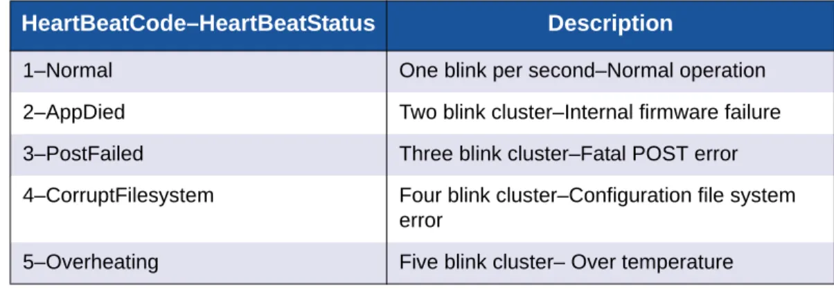
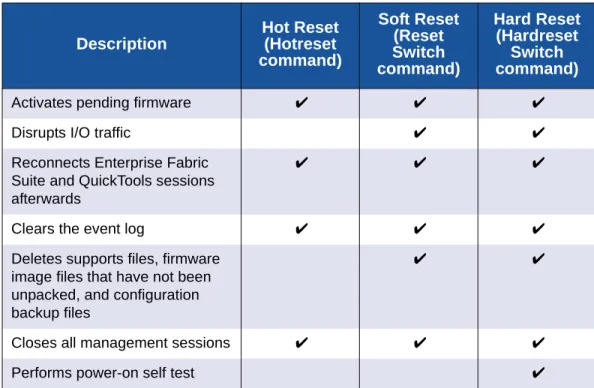
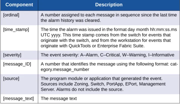
Table Page 1-1 Command-Line Completion . . . 1-4 2-1 Factory User Accounts. . . 2-1 4-1 Heartbeat LED Activity . . . 4-7 4-2 Switch Reset Methods . . . 4-19 10-1 Event Log Message Format . . . 10-2 13-1 Data Capture Configuration Parameters . . . 13-1013-2 ISL Group Member Attributes . . . 13-33 13-3 Port Group Member Attributes . . . 13-34 13-4 MS Group Member Attributes . . . 13-35 13-5 Group Member Attributes. . . 13-36 13-6 IKE Peer Configuration Parameters. . . 13-47 13-7 IKE Policy Configuration Parameters . . . 13-53 13-8 IP Security Association Configuration Parameters . . . 13-65 13-9 IP Security Policy Configuration Parameters . . . 13-72 13-10 Profile Configuration Parameters . . . 13-83 13-11 Call Home Service Configuration Defaults. . . 13-92 13-12 Switch Configuration Defaults . . . 13-93 13-13 Port Configuration Defaults . . . 13-94 13-14 Port Threshold Alarm Configuration Defaults. . . 13-95 13-15 Zoning Configuration Defaults . . . 13-96 13-16 SNMP Configuration Defaults . . . 13-96 13-17 RADIUS Configuration Defaults . . . 13-97 13-18 Switch Services Configuration Defaults . . . 13-97 13-19 System Configuration Defaults. . . 13-98 13-20 Security Configuration Defaults . . . 13-98 13-21 Port Configuration Parameters. . . .13-108 13-22 Security Configuration Parameters . . . .13-113 13-23 Port Binding Configuration Parameters . . . .13-114 13-24 Switch Configuration Parameters. . . .13-115 13-25 Port Alarm Threshold Parameters . . . .13-117 13-26 Zoning Configuration Parameters . . . .13-119 13-27 Call Home Service Configuration Settings . . . .13-128 13-28 Common RADIUS Configuration Parameters . . . .13-131 13-29 Specific RADIUS Server Configuration Parameters. . . .13-132 13-30 Switch Services Settings . . . .13-135 13-31 SNMP Common Configuration Parameters . . . .13-138 13-32 SNMP Trap Configuration Parameters. . . .13-139 13-33 DNS Host Name Configuration Parameters. . . .13-142 13-34 IP Version 4 Ethernet Configuration Parameters . . . .13-143 13-35 IP Version 6 Ethernet Configuration Parameters . . . .13-143 13-36 Event Logging Configuration Parameters . . . .13-144 13-37 NTP Server Configuration Parameters . . . .13-144 13-38 Timer Configuration Parameters . . . .13-145 13-39 Show About Display Entries. . . .13-152 13-40 Log Monitoring Components . . . .13-170 13-41 Transceiver Information . . . .13-175 13-42 Show Port Parameters . . . .13-185 13-43 Switch Operational Parameters . . . .13-201 13-44 Show Version Display Entries . . . .13-208 13-45 SNMP Version 3 User Account Parameters. . . .13-211 13-46 Port Test Parameters . . . .13-215
13-47 Switch Test Parameters . . . .13-219 13-48 Zoning Database Limits . . . .13-239
This guide describes the features and use of the command line interface for QLogic 5800V Series Fibre Channel switches running firmware version 8.0. The QLogic 5800V Series switch is a 24-port, 8-Gbps Fibre Channel switch. The model 5802V switch has dual, replaceable power supplies; model 5800V has a single non-replaceable power supply. This guide is organized as follows:
Section 1 describes logging on and off of a switch, opening and closing an Admin session, entering commands, getting help, paging a switch, setting page breaks, and loading and retrieving files.
Section 2 describes the management of user accounts and passwords. Section 3 describes configuring the switch network configuration.
Section 4 describes managing the switch configuration, setting the date and time, backing up and restoring the switch configuration, resetting the switch, installing firmware, and installing feature licenses.
Section 5 describes port configurations, resetting a port, initializing a port loop, configuring port threshold alarms, and testing ports.
Section 6 describes managing the zoning database. Section 7 describes managing connection security. Section 8 describes managing device security.
Section 9 describes managing the Remote Authentication Dial-In User Service (RADIUS) server.
Section 10 describes events and event logging.
Section 11 describes managing Call Home email notification.
Section 12 describes managing the Simple Network Management Protocol (SNMP) configuration.
Section 13 lists the commands in alphabetical order, including the command syntax, keywords, notes, and examples.
Switch Models and Examples
The commands and displays of the command line interface vary depending on the switch model. All examples in this guide are taken from a QLogic 5802V switch unless stated otherwise.
Intended Audience
This guide is intended for individuals who are responsible for installing and servicing Fibre Channel equipment using the command line interface.
Related Materials
The following manuals and materials are referenced in the text and/or provide additional information.
QLogic 5800V Series Stackable Fibre Channel Switch Installation Guide
QLogic 5800V Series QuickTools Switch Management User’s Guide
QLogic 5800V Series Enterprise Fabric Suite User’s Guide
QLogic Fibre Channel Switch Event Message Reference Guide
Simple Network Management Protocol Reference Guide
CIM Agent Reference Guide
QLogic Storage Networking Interoperability Guide. This PDF document can be downloaded at www.qlogic.com.
Fibre Channel-Arbitrated Loop (FC-AL-2) Rev. 7.0. Fibre Channel-10-bit Interface Rev. 2.3.
Definitions of Managed Objects for the Fabric Element in Fibre Channel Standard (draft-ietf-ipfc-fabric-element-mib-04.txt).
The Fibre Channel Standards are available from:
Global Engineering Documents, 15 Inverness Way East, Englewood, CO 80112-5776 Phone: (800) 854-7179 or (303) 397-7956
Fax: (303) 397-2740.
Technical Support
Customers should contact their authorized maintenance provider for technical support of their QLogic products. QLogic-direct customers may contact QLogic Technical Support; others will be redirected to their authorized maintenance provider. Visit the QLogic support Web site listed in Contact Information for the latest firmware and software updates.
For details about available service plans, or for information about renewing and extending your service, visit the Service Program web page at
http://www.qlogic.com/services.
Training
QLogic offers training for technical professionals for all iSCSI, InfiniBand, and Fibre Channel products. From the main QLogic web page at www.qlogic.com, click the Support tab at the top, and then click Training and Certification on the left. The QLogic Global Training portal offers online courses, certification exams, and scheduling of in-person training.
Technical Certification courses include installation, maintenance and
troubleshooting QLogic products. Upon demonstrating knowledge using live equipment, QLogic awards a certificate identifying the student as a certified professional. You can reach the training professionals at QLogic by e-mail at [email protected].
Contact Information
QLogic Technical Support for products under warranty is available during local standard working hours excluding QLogic Observed Holidays. For customers with extended service, consult your plan for available hours. For Support phone numbers, see the Contact Support link at support.qlogic.com.
Support Headquarters QLogic Corporation 4601 Dean Lakes Blvd. Shakopee, MN 55379 USA QLogic Web Site www.qlogic.com
Technical Support Web Site http://support.qlogic.com Technical Support E-mail [email protected] Technical Training E-mail [email protected]
Knowledge Base
The QLogic knowledge base is an extensive collection of QLogic product
information that you can search for specific solutions. We are constantly adding to the collection of information in our knowledge base to provide answers to your most urgent questions. Access the knowledge base from the QLogic Support Center: http://support.qlogic.com.
Usage
This section describes the following tasks: Logging In to the Switch
Opening and Closing an Admin Session Entering Commands
Getting Help
Setting Page Breaks Creating a Support File
Downloading and Uploading Files
NOTE:
Throughout this document, references in text to commands and keywords use initial capitalization for clarity. Actual command and keyword entries are case insensitive
Logging In to the Switch
To log in to a switch through Telnet, do the following:
1. Open a command line window on the workstation and enter the Telnet command followed by the switch IP address. The IP address can be one of the following:
4-byte IP version 4 address 16-byte IP version 6 address
Domain Name System (DNS) host name (requires a DNS server) The Telnet window opens prompting you for a login.
# telnet ip_address
2. Enter an account name and password. The default account name is admin, and its password is password.
switch login:admin password: xxxxxxxx
The following warning appears when you log in for the first time: Warning: Your user account password has not been changed It is strongly recommended that you do so before proceeding
To log off, enter the Exit command: SANbox #> exit
To log in to a switch through the serial port, do the following: 1. Configure the workstation port with the following settings:
9600 baud 8-bit character 1 stop bit No parity
2. Enter an account name and password when prompted. The default account name is admin, and its password is password.
Opening and Closing an Admin Session
The command line interface performs monitoring and configuration tasks. Commands that perform monitoring tasks are available to all user accounts. Commands that perform configuration tasks are available only after entering the Admin Start command to open an Admin session. A user account must have Admin authority to enter the Admin Start command.
The following is an example of how to open and close an Admin session: SANbox #> admin start
SANbox (admin) #> .
. .
SANbox (admin) #> admin end
NOTE:
A switch supports a combined maximum of 19 logins or sessions, which are reserved as follows. Additional logins will be refused.
4 logins or sessions for internal applications such as management server and SNMP
9 high priority Telnet sessions
6 logins or sessions for Enterprise Fabric Suite™, QuickTools™, Application Programming Interface (API) , and Telnet.
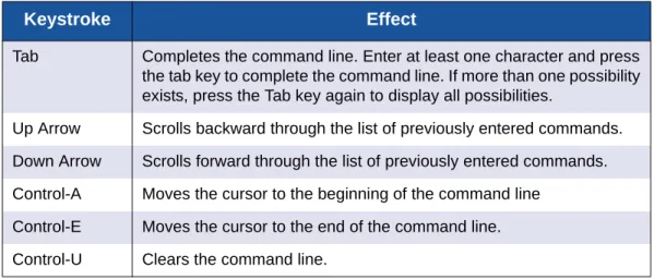
Entering Commands
The command-line completion feature makes entering and repeating commands easier. Table 1-1 describes the command-line completion keystrokes.
Getting Help
To display help for a command, enter the Help command followed by the
command you are inquiring about. The following is an example of the help that is available for the ConfigEdit command.
SANbox #> help config edit config edit [CONFIG_NAME]
This command initiates a configuration session and places the current session into config edit mode.
If CONFIG_NAME is given and it exists, it gets edited; otherwise, it gets created. If it is not given, the currently active configuration is edited. Admin mode is required for this command.
Usage: config edit [CONFIG_NAME]
Table 1-1. Command-Line Completion
Keystroke Effect
Tab Completes the command line. Enter at least one character and press the tab key to complete the command line. If more than one possibility exists, press the Tab key again to display all possibilities.
Up Arrow Scrolls backward through the list of previously entered commands. Down Arrow Scrolls forward through the list of previously entered commands. Control-A Moves the cursor to the beginning of the command line
Control-E Moves the cursor to the end of the command line. Control-U Clears the command line.
Setting Page Breaks
Some display commands deliver so much information to the screen that it scrolls by too quickly to read it. You can limit the display to 20 lines by turning on page breaks. By default, page breaks are turned off.The following is an example of how to turn page breaks on and how it affects the display.
SANbox #> set pagebreak on SANbox #> zone list Zone ZoneSet ---- Zone1 alpha beta Zone2 delta echo Zone3 sierra tango Zone4 gamma delta
Press any key to continue, 'q' to quit ...
Creating a Support File
If you contact technical support about a problem with your switch, they may request that you create and send a support file. This support file contains all of the switch configuration information, which can be helpful in diagnosing the problem. The Create Support command creates the support file (dump_support.tgz) on the switch. If your workstation has an FTP server, you can proceed with the command prompts to send the file from the switch to a remote host. Otherwise, you can use FTP to download the support file from the switch to your workstation.
The following example creates a support file and sends it to a remote host if your workstation has an FTP server.
SANbox #> create support
Log Msg:[Creating the support file - this will take several seconds] FTP the dump support file to another machine? (y/n): y
Enter IPv4, IPv6 Address or hostname of remote computer: 10.20.33.130 Login name: johndoe
Enter remote directory name: bin/support
Would you like to continue downloading support file? (y/n) [n]: y Connected to 10.20.33.130 (10.20.33.130).
220 localhost.localdomain FTP server (Version wu-2.6.1-18) ready. 331 Password required for johndoe.
Password: xxxxxxx
230 User johndoe logged in. cd bin/support
250 CWD command successful. lcd /itasca/conf/images
Local directory now /itasca/conf/images bin
200 Type set to I. put dump_support.tgz
local: dump_support.tgz remote: dump_support.tgz 227 Entering Passive Mode (10,20,33,130,232,133)
150 Opening BINARY mode data connection for dump_support.tgz. 226 Transfer complete.
43430 bytes sent in 0.292 secs (1.5e+02 Kbytes/sec) Remote system type is UNIX.
Using binary mode to transfer files.
221-You have transferred 43430 bytes in 1 files.
221-Total traffic for this session was 43888 bytes in 1 transfers. 221 Thank you for using the FTP service on localhost.localdomain.
NOTE:
Support files are deleted from the switch during a power cycle or switch reset.
If your workstation does not have an FTP server, enter the Create Support command to create the support file, and then use FTP to download the support file from the switch to your workstation, as shown in the following example:
SANbox #> create support
Log Msg:[Creating the support file - this will take several seconds] FTP the dump support file to another machine? (y/n): n
To download the support file from the switch to the workstation, do the following: 1. Open a terminal window and move to the directory where you want to
download the support file.
2. Enter the FTP command and the switch IP address or symbolic name. >ftp 10.0.0.1
3. When prompted for a user and password, enter the FTP account name and password (images, images).
user: images password: images
4. Set binary mode and use the Get command to download the file (dump_support.tgz).
ftp>bin
ftp>get dump_support.tgz
xxxxx bytes sent in xx secs. ftp>quit
Downloading and Uploading Files
Several files that reside on the switch can be downloaded to the workstation for examination or for safekeeping. These files include the following:
Backup configuration file (configdata) Log files (logfile)
Support files (dump_support.tgz)
You can upload firmware image files or backup configuration files to the switch to reinstall firmware or restore a corrupted configuration. The switch uses FTP to exchange files between the switch and the workstation.
To download a file from the switch to the workstation, do the following: 1. Enter the FTP command and the switch IP address or symbolic name.
>ftp 10.0.0.1
2. When prompted for a user and password, enter the FTP account name and password (images, images).
user: images password: images
3. Set binary mode and use the Get command to download the file (configdata).
ftp>bin
ftp>get configdata
xxxxx bytes sent in xx secs. ftp>quit
To upload a file from the workstation to the switch, do the following
1. Enter the FTP command and the switch IP address or symbolic name. >ftp 10.0.0.1
2. When prompted for a user and password, enter the FTP account name and password (images, images).
user:images password: images
3. Set binary mode and use the Put command to upload the file (config_switch_169).
ftp>put config_switch_169 configdata xxxxx bytes sent in xx secs. ftp>quit
For more information about reinstallation, backup and restore, and creating support and log files:
Refer to “Installing Firmware” on page 4-19 for information about installing firmware.
Refer to “Backing Up and Restoring a Switch Configuration” on page 4-13 for information about backing up and restoring a switch configuration. Refer to “Creating and Downloading a Log File” on page 10-6 for information
about creating a log file.
Refer to “Creating a Support File” on page 1-6 for information about creating a support file.
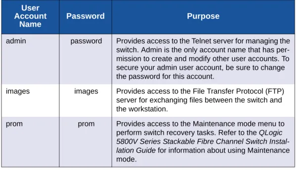
Configuration
User accounts and their respective passwords are the first line of switch security. A user account consists of an account name, an authority level, and an expiration date. Switches come from the factory with certain user accounts defined for special purposes. Table 2-1 describes these accounts, their passwords, and their purposes. These accounts cannot be deleted from the switch.
This section describes the following user account configuration tasks: Displaying User Account Information
Creating User Accounts
Modifying User Accounts and Passwords
Table 2-1. Factory User Accounts
User Account
Name
Password Purpose
admin password Provides access to the Telnet server for managing the switch. Admin is the only account name that has per-mission to create and modify other user accounts. To secure your admin user account, be sure to change the password for this account.
images images Provides access to the File Transfer Protocol (FTP) server for exchanging files between the switch and the workstation.
prom prom Provides access to the Maintenance mode menu to perform switch recovery tasks. Refer to the QLogic 5800V Series Stackable Fibre Channel Switch Instal-lation Guide for information about using Maintenance mode.
Displaying User Account Information
You can display all user accounts defined on the switch (User Accounts command) or just those user accounts that are logged on (User List or Show Users commands).
The following example displays all user accounts defined on the switch. Account information includes account name, authority, and expiration date.
SANbox (admin) #> user accounts Current list of user accounts
images (admin authority = False, never expires) admin (admin authority = True , never expires) chuckca (admin authority = False, expires in < 50 days) gregj (admin authority = True , expires in < 100 days) fred (admin authority = True , never expires)
The following example displays user accounts that are logged on to the switch:
SANbox (admin) #> user list
User cim@OB-session1 Client cim
Logged in Since day month date time year User snmp@IB-session2
Client Unknown
Logged in Since day month date time year User snmp@OB-session3
Client Unknown
Logged in Since day month date time year User admin@OB-session8 Client 10.33.21.27
Logged in Since day month date time year
Creating User Accounts
A user account consists of an account name, an authority level, and an expiration date. The account name can be up to 15 characters: the first character must be alphanumeric; the remaining characters must be ASCII characters except semicolon (;), comma (,), #, and period (.). The authority level grants admin authority (true) or denies it (false). The expiration date sets the date when the user account expires. Only the Admin user account can create user accounts. You add user accounts with the User Add command.
The following example creates a new user account named user1 with admin authority that expires in 100 days.
SANbox (admin) #> user add
Press 'q' and the ENTER key to abort this command. account name (1-15 chars) : user1
account password (8-20 chars) : ******* please confirm account password: *******
set account expiration in days (0-2000, 0=never): [0] 100 should this account have admin authority? (y/n): [n] y OK to add user account 'user1' with admin authority and to expire in 100 days?
Please confirm (y/n): [n] y
Modifying User Accounts and Passwords
Only the Admin user account can modify a user account, delete a user account, or change the password of another user account. However, all user accounts can change their own passwords. The User command modifies and deletes user accounts. The Passwd command changes passwords.
The following example removes the expiration date and admin authority for the user account named user1.
SANbox (admin) #> user edit
Press 'q' and the ENTER key to abort this command. account name (1-15 chars) : user1
set account expiration in days (0-2000, 0=never): [0] should this account have admin authority? (y/n): [n] OK to modify user account 'user1' with no admin authority and to expire in 0 days?
Please confirm (y/n): [n]
The following example deletes the user account named user3.
SANbox (admin) #> user delete user3
The user account will be deleted. Please confirm (y/n): [n] y
In the following example, the Admin user account changes the password for the user account named user2.
SANbox #> admin start
SANbox (admin) #> passwd user2
Press 'q' and the ENTER key to abort this command. account OLD password : ********
account NEW password (8-20 chars) : ******** please confirm account NEW password: ******** password has been changed.
Network configuration consists of the IP parameters that identify the switch in the network and provide for IP security. This section describes the following network configuration tasks:
Displaying the Network Configuration Configuring the Ethernet Port
Verifying a Switch in the Network Managing IP Security
Displaying the Network Configuration
The Show Fabric command displays IP addresses for all switches in the fabric as shown in the following example.
SANbox #> show fabric
Domain *133(0x85) WWN 10:00:00:c0:dd:0d:53:91 SymbolicName SANbox HostName <undefined> EthIPv4Address 10.20.116.133 EthIPv6Address <undefined> * indicates principal switch
The Show Setup System command displays the entire switch network configuration, which includes the following:
IP configurations (versions 4 and 6) DNS server configuration
To display specific information, add the corresponding keyword. For example, to display IP version 6 configuration information, enter the Show Setup System Ipv6 command:
SANbox #> show setup system ipv6 System Information EthIPv6NetworkEnable False EthIPv6NetworkDiscovery Static EthIPv6NetworkAddress 2001::1/64 EthIPv6GatewayAddress fe80::1
Configuring the Ethernet Port
Use the Set Setup System command in an Admin session to configure the Ethernet port and other network parameters. You can configure all of the following parameters in one session, or you can configure specific parameters by adding the corresponding keyword:
IP Version 4 Configuration IP Version 6 Configuration DNS Server Configuration
IP Version 4 Configuration
The switch supports IP version 4, which includes the following: Network discovery method
IP address Subnet mask IP gateway address
The network discovery method determines how the switch acquires its IP address. The IP address can come from the IP address that resides on the switch or from a server. The switch supports network discovery from the following server types: Bootstrap Protocol (BootP)
Reverse Address Resolution Protocol (RARP) Dynamic Host Configuration Protocol (DHCP)
To configure the IP version 4 parameters, enter the Set Setup System Ipv4 command:
SANbox (admin) #> set setup system ipv4
A list of attributes with formatting and current values will follow.
Enter a new value or simply press the ENTER key to accept the current value. If you wish to terminate this process before reaching the end of the list press 'q' or 'Q' and the ENTER key to do so.
Current Values: EthIPv4NetworkEnable True EthIPv4NetworkDiscovery Static EthIPv4NetworkAddress 10.20.116.133 EthIPv4NetworkMask 255.255.255.0 EthIPv4GatewayAddress 10.20.116.1
New Value (press ENTER to accept current value, 'q' to quit, 'n' for none): EthIPv4NetworkEnable (True / False) :
EthIPv4NetworkDiscovery (1=Static, 2=Bootp, 3=Dhcp, 4=Rarp) :
EthIPv4NetworkAddress (dot-notated IP Address) : 10:20:30:40 EthIPv4NetworkMask (dot-notated IP Address) : 255.0.0.0 EthIPv4GatewayAddress (dot-notated IPv4 Address) : 10.20.30.254 Do you want to save and activate this system setup? (y/n): [n] y
IP Version 6 Configuration
The switch supports IP version 6, which includes the following: Network discovery method
IP address
IP gateway address
The network discovery method determines how the switch acquires its IP address. The IP address can come from the IP address (static) that resides on the switch, from a DHCP server, or it can be learned from a router through the Neighbor Discovery Protocol (NDP). To configure the IP version 6 parameters, enter the Set Setup System Ipv6 command:
SANbox (admin) #> set setup system ipv6
A list of attributes with formatting and current values will follow.
Enter a new value or simply press the ENTER key to accept the current value. If you wish to terminate this process before reaching the end of the list press 'q' or 'Q' and the ENTER key to do so.
Current Values:
EthIPv6NetworkEnable False EthIPv6Discovery Static EthIPv6NetworkAddress <undefined> EthIPv6GatewayAddress <undefined>
New Value (press ENTER to accept current value, 'q' to quit, 'n' for none): EthIPv6NetworkEnable (True / False) :
EthIPv6Discovery (1=Static, 2=Dhcpv6, 3=Ndp) : EthIPv6NetworkAddress (IPv6 Address/Mask Length format) : EthIPv6GatewayAddress (IPv6 Address) : Do you want to save and activate this system setup? (y/n): [n]
DNS Server Configuration
A DNS server manages the host names for a fabric. This enables you to specify servers and switches by a meaningful name rather than IP address. To configure a DNS server, enter the Set Setup System Dns command in an Admin session as shown in the following example:
SANbox (admin) #> set setup system dns
A list of attributes with formatting and current values will follow.
Enter a new value or simply press the ENTER key to accept the current value. If you wish to terminate this process before reaching the end of the list press 'q' or 'Q' and the ENTER key to do so.
Current Values: DNSClientEnabled False DNSLocalHostname <undefined> DNSServerDiscovery Static DNSServer1Address <undefined> DNSServer2Address <undefined> DNSServer3Address <undefined> DNSSearchListDiscovery Static DNSSearchList1 <undefined> DNSSearchList2 <undefined> DNSSearchList3 <undefined> DNSSearchList4 <undefined> DNSSearchList5 <undefined>
New Value (press ENTER to accept current value, 'q' to quit, 'n' for none): DNSClientEnabled (True / False) :
DNSLocalHostname (hostname) : DNSServerDiscovery (1=Static, 2=Dhcp, 3=Dhcpv6) : DNSServer1Address (IPv4, or IPv6 Address) : DNSServer2Address (IPv4, or IPv6 Address) : DNSServer3Address (IPv4, or IPv6 Address) : DNSSearchListDiscovery (1=Static, 2=Dhcp, 3=Dhcpv6) : DNSSearchList1 (domain name) : DNSSearchList2 (domain name) : DNSSearchList3 (domain name) : DNSSearchList4 (domain name) : DNSSearchList5 (domain name) : Do you want to save and activate this system setup? (y/n): [n]
Verifying a Switch in the Network
You can verify that a switch is communicating in the network using the Ping command. The following example successfully tests the network for a switch with IP address 10.20.11.57.
SANbox #> ping 10.20.11.57
Ping command issued. Waiting for response... SANbox #>
Response successfully received from 10.20.11.57.
If the switch was unreachable, you would see the following display.
SANbox #> ping 10.20.11.57
Ping command issued. Waiting for response... No response from 10.20.11.57. Unreachable.
Managing IP Security
To modify IP Security, you must open an Admin session with the Admin Start command. An Admin session prevents other accounts from making changes at the same time through Telnet, QuickTools, Enterprise Fabric Suite, or another management application. You must also open an Ipsec Edit session with the Ipsec Edit command. The Ipsec Edit session provides access to the Ipsec,
Ipsec Association, Ipsec Policy, Ike Peer, and Ike Policy commands with which you make modifications to the IP security and Internet key exchange (IKE) configurations.
SANbox #> admin start
SANbox (admin) #> ipsec edit
SANbox (admin-ipsec)#> ipsec . . .
SANbox (admin-ipsec)#> ipsec policy . . . SANbox (admin-ipsec)#> ipsec association. . . SANbox (admin-ipsec)#> ike peer . . .
SANbox (admin-ipsec)#> ike policy . . .
When you are finished making changes, enter the Ipsec Save command to save and activate the changes and close the Ipsec Edit session. Changes take effect immediately.
SANbox (admin-ipsec)#> ipsec save
To close the Ipsec Edit session without saving changes, enter the Ipsec Cancel command.
SANbox (admin-ipsec)#> ipsec cancel
The Admin End command releases the Admin session for other administrators when you are done making changes to the switch.
To remove all IP security policies, security associations, IKE peers, and IKE policies, enter the Reset Ipsec command.
SANbox (admin) #> reset ipsec
The following subsections present IP security concepts and management tasks: IP Security Concepts
Displaying IP Security Information Managing the Security Policy Database Managing the Security Association Database Managing IKE Peers
Managing IKE Policies
Resetting the IP Security Configuration
IP Security Concepts
IP security provides encryption-based security for IPv4 and IP6 communications between devices through the use of security policies and associations. The Internet key exchange (IKE) protocol automates the creation of IP security associations on the switch and connected devices and the sharing of encryption keys through the configuration of IKE peers and policies. The security association database comprises all IP security associations. The security policy database comprises all IP security policies. The IKE database comprises all IKE policies and peers.
Security Policies and Associations
A security policy defines the following parameters: Connection source and destination
Data traffic direction: inbound or outbound Protocols for which to protect data traffic
Security protocols; authentication header (AH) or encapsulating security payload (ESP)
Level of protection: IP security, discard, or none NOTE:
IP security configurations can be complex: it is possible to unintentionally isolate a switch from all communication. If this happens, you can disable IP security by placing the switch in maintenance mode, and correct the
problem through the serial port interface. For information about using maintenance mode and connecting through the serial port, see the QLogic 5800V Series Stackable Fibre Channel Switch Installation Guide.
Policies can define security for host-to-host and host-to-gateway connections; one policy for each direction. For example, to secure the connection between two hosts, you need two policies: one for outbound traffic from the source to the destination, and another for inbound traffic to the source from the destination. You can specify sources and destinations by IP addresses (version 4 or 6) or DNS host names. If a host name resolves to more than one IP address, the switch creates the necessary policies and associations. You can recognize these dynamic policies and associations because their names begin with DynamicSP_
and DynamicSA_ respectively.
A security association defines the encryption algorithm and encryption key (public key or secret) to apply when called by a security policy. A security policy may call several associations at different times, but each association is related to only one policy. The security association database is the set of all security associations. You can apply IP security to all communication between two systems, or to selected protocols, such as ICMP, TCP, or UDP. Furthermore, instead of applying IP security, you can choose to discard all inbound or outbound traffic, or allow all traffic without encryption. Both the AH and ESP security protocols provide source authentication, ensure data integrity, and protect against replay.
IKE Peers and Policies
IKE is a protocol that automates the configuration of matching IP security associations on the switch and on the connected device (or peer). The IKE peer
defines the IKE security association connection through which the IKE policy configures the IP security associations.The IKE policy defines the type of data traffic to secure between the switch and the peer, and how to encrypt that data. You must create the same IKE peer and IKE policy configurations on the switch and the peer device.
Public Key Infrastructure
Public key encryption requires a public key, a corresponding private key, and the necessary certificates to authenticate them. Public key infrastructure (PKI) provides support for the creation and management of public/private key pairs, signed certificates, and certificate authority (CA) certificates when using IKE. You can create a public/private key and combine it with one or more device identities to generate a certificate request. Submit the certificate request to a CA to obtain a signed certificate, which contains the authenticated public/private key pair. In addition to the signed certificate, you must also obtain a CA certificate to
authenticate the CA. After downloading the signed certificate and a CA certificate to the switch and importing them into the PKI database, the signed certificate (which contains the authenticated public key) can then be used to complete the IKE peer configuration.
Displaying IP Security Information
You can display the following types of IP security information: IP Security Policy and Association Information
Public Key Infrastructure Information IKE Peer and Policy Information IP Security Configuration History IP Security Configuration Limits
IP Security Policy and Association Information
To display general or specific security policy and association information, enter the Ipsec List command. The Ipsec List command does not require an Admin session nor an Ipsec Edit session. Within an Ipsec Edit session, the Ipsec Association List and Ipsec Policy List commands display the same information. You can display active, configured, and edited polices and associations:
Active—policies and associations currently in use
Configured—policies and associations that have been saved in the IP security database
Edited—policies and associations that are being edited, but have not yet been saved
The following example displays all active security policies and associations:
SANbox #> ipsec list Active IPsec Information Security Association Database h2h-sh-sa
h2h-hs-sa
Security Policy Database h2h-hs-sp
h2h-sh-sp Summary
Security Association Count: 2 Security Policy Count: 2
IKE Peer and Policy Information
To display general or specific peer and policy information, enter the Ike List command. The Ike List command does not require an Admin session nor an Ipsec Edit session. The Ike Peer List and Ike Policy List commands display the same information. You can display active, configured, and edited peers and polices: Active—peers and policies currently in use
Configured—peers and policies that have been saved in the IKE database Edited—peers and policies that are being edited, but have not yet been
saved
The following example displays all configured IKE peers and policies:
SANbox #> ike list configured
Configured (saved) IKE Information Peer Policy -- peer_1 policy_1 policy_2 peer_2 policy_3 peer_3 (no policies) (No peer) policy_4 Summary: Peer Count 3 Policy Count 4
Public Key Infrastructure Information
To display information in the PKI database about public/private key pairs, signed certificates, and certificate authorities, enter the following commands:
Key List
Certificate List Local Cert_Authority List
The following is an example of the Key List command for key512:
SANbox #> key list key512 Key key512:
private key with: pubkey: RSA 512 bits
keyid: 49:80:4c:aa:d3:c3:bc:c7:f5:b1:41:34:ce:71:48:1d:b9:b3:d9:f9 subjkey: f4:b6:b9:27:25:7a:5a:69:a0:9e:cf:14:cd:3c:88:e9:d5:b1:aa:4a
The following is an example of the Key List command:
SANbox #> key list Installed Keys: key512
key2048 key1024
* indicates key has a matching local certificate
IP Security Configuration History
To display the IP Security configuration history, enter the IpsecHistory command to display a record of policy and association modifications as shown in the following example:
SANbox #> ipsec history IPsec Database History
ConfigurationLastEditedBy johndoe@OB-session5 ConfigurationLastEditedOn Sat Mar 8 07:14:36 2008 Active Database Checksum 00000144
Inactive Database Checksum 00000385 IKE Database Checksum 00000023
History information includes the following:
Time of the most recent activation and the user account that performed it Time of the most recent modification to the IP Security configuration and the
user account that made it
Checksum for the active and inactive databases
IP Security Configuration Limits
To display a summary of the objects in the IP Security configuration and their maximum limit, enter the IpsecLimits command to as shown in the following example:
SANbox #> ipsec limits
Configured (saved) IPsec Information
IPsec Attribute Maximum Current - MaxConfiguredSAs 512 0 MaxConfiguredSPs 128 0 MaxConfiguredIKEPeers 16 0 MaxConfiguredIKEPolicies 256 0
In an Ipsec Edit session, Ipsec Limits command displays the number of both configured associations and policies, plus those created in the edit session but not yet saved.
Managing the Security Policy Database
The security policy database is made up of user-defined policies and dynamic policies (policies created by the switch). In addition to creating a policy, you can delete, modify, rename, and copy user-defined policies. Dynamic policies can only be copied.
Creating a Policy Deleting a Policy
Modifying a User-Defined Policy Renaming a User-Defined Policy Copying a Policy
Creating a Policy
To create a policy, enter the Ipsec Policy Create command as shown in the following example:
SANbox #> admin start SANbox (admin) #> ipsec edit
SANbox (admin-ipsec) #> ipsec policy create h2h-sh-sp A list of attributes with formatting will follow.
Enter a value or simply press the ENTER key to skip specifying a value. If you wish to terminate this process before reaching the end of the list press 'q' or 'Q' and the ENTER key to do so.
Required attributes are preceded by an asterisk. Value (press ENTER to not specify value, 'q' to quit):
Description (string value, 0-127 bytes) : Host-to-host: switch->host *SourceAddress (hostname, IPv4, or IPv6 Address/[PrefixLength]): fe80::2c0:ddff:fe03:d4c1 SourcePort (decimal value, 1-65535) :
*DestinationAddress (hostname, IPv4, or IPv6 Address/[PrefixLength]): fe80::250:daff:feb7:9d02 DestinationPort (decimal value, 1-65535) :
*Protocol (decimal value, or keyword) Allowed keywords
icmp, icmp6, ip4, tcp, udp or any : any *Direction (1=in, 2=out) : 2 Priority (value, -2147483647 to +214783647) : *Action (1=discard, 2=none, 3=ipsec) : 3 Mode (1=transport, 2=tunnel) : 2
*TunnelSource (IPv4, or IPv6 Address) : fe91::3d1:eegg:gf14:e5d2 *TunnelDestination (IPv4, or IPv6 Address) : fe91::361:ebgg:gfc8:0e13 *ProtectionDesired (select one, transport-mode only)
1=ah Authentication Header
2=esp Encapsulating Security Payload
3=both : 2 *espRuleLevel (1=default, 2=use, 3=require) : 3 The security policy has been created.
This configuration must be saved with the 'ipsec save' command before it can take effect, or to discard this configuration use the 'ipsec cancel' command.
Deleting a Policy
To delete a user-defined policy, enter the Ipsec Policy Delete command as shown in the following example:
SANbox #> admin start SANbox (admin) #> ipsec edit
SANbox (admin-ipsec) #> ipsec policy delete policy_1
The security policy will be deleted. Please confirm (y/n): [n] y SANbox (admin-ipsec) #> ipsec save
The IPsec configuration will be saved and activated. Please confirm (y/n): [n] y
Modifying a User-Defined Policy
To modify an existing user-defined policy, enter the Ipsec Policy Edit command in an Admin session and an Ipsec Edit session as shown in the following example. An asterisk (*) indicates a required entry.
SANbox (admin-ipsec) #> ipsec policy edit h2h-sh-sp
A list of attributes with formatting and current values will follow.
Enter a new value or simply press the ENTER key to accept the current value. To remove a value for an optional attribute, use ’n’.
If you wish to terminate this process before reaching the end of the list press 'q' or 'Q' and the ENTER key to do so.
Current Values:
Description Host-to-host: switch->host .
. .
espRuleLevel require
New Value (press ENTER to not specify value, 'q' to quit, 'n' for none): Description (string value, 0-127 bytes) :
*SourceAddress (IPv4, IPv6 or hostname/[PrefixLength]) : SourcePort (decimal value, 1-65535) : *DestinationAddress (IPv4, IPv6 or hostname/[PrefixLength]) : DestinationPort (decimal value, 1-65535) : *Protocol (decimal value, or keyword)
Allowed keywords
icmp, icmp6, ip4, tcp, udp or any : tcp *Direction (1=in, 2=out) : Priority (value, -2147483647 to +2147483647) : *Action (1=discard, 2=none, 3=ipsec) : Mode (1=transport, 2=tunnel) : *TunnelSource (IPv4, or IPv6 Address) : *TunnelDestination (IPv4, or IPv6 Address) : *ProtectionDesired (select one, transport-mode only)
2=esp Encapsulating Security Payload
3=both : *ahRuleLevel (1=default, 2=use, 3=require) : *espRuleLevel (1=default, 2=use, 3=require) : The security policy has been edited.
This configuration must be saved with the 'ipsec save' command before it can take effect, or to discard this configuration use the 'ipsec cancel' command.
SANbox (admin-ipsec) #> ipsec save
The IPsec configuration will be saved and activated. Please confirm (y/n): [n] y
Renaming a User-Defined Policy
To rename a policy (policy_1), enter the Ipsec Policy Rename command as shown in the following example:
SANbox #> admin start SANbox (admin) #> ipsec edit
SANbox (admin-ipsec) #> ipsec policy rename policy_1 policy_4 The security policy will be renamed. Please confirm (y/n): [n] y SANbox (admin-ipsec) #> ipsec save
The IPsec configuration will be saved and activated. Please confirm (y/n): [n] y
Copying a Policy
You can copy both user-defined and dynamic policies. To copy a policy (policy_1), enter the Ipsec Policy Copy command as shown in the following example:
SANbox #> admin start SANbox (admin) #> ipsec edit
SANbox (admin-ipsec) #> ipsec policy copy policy_1 policy_a SANbox (admin-ipsec) #> ipsec save
The IPsec configuration will be saved and activated. Please confirm (y/n): [n] y
Managing the Security Association Database
The security association database is made up of user-defined associations and dynamic associations (associations created by the switch). In addition to creating an association, you can delete, modify, rename, and copy user-defined
associations. Dynamic associations can only be copied. Creating an Association
Deleting an Association
Modifying a User-Defined Association Renaming a User-Defined Association Copying an Association
Creating an Association
To create an association, enter the Ipsec Association Create command as shown in the following example:
SANbox #> admin start SANbox (admin) #> ipsec edit
SANbox (admin-ipsec) #> ipsec association create h2h-sh-sa A list of attributes with formatting will follow.
Enter a value or simply press the ENTER key to skip specifying a value. If you wish to terminate this process before reaching the end of the list press 'q' or 'Q' and the ENTER key to do so.
Required attributes are preceded by an asterisk. Value (press ENTER to not specify value, 'q' to quit):
Description (string value, 0-127 bytes) : Host-to-host: switch->host *SourceAddress (hostname, IPv4, or IPv6 Address) : fe80::2c0:ddff:fe03:d4c1 *DestinationAddress (hostname, IPv4, or IPv6 Address) : fe80::250:daff:feb7:9d02 *Protocol (1=esp, 2=esp-old, 3=ah, 4=ah-old) : 1
*SPI (decimal value, 256-4294967295) : 333 Authentication (select an authentication algorithm) 1=hmac-md5 (16 byte key) 2=hmac-sha1 (20 byte key) 3=hmac-sha256 (32 byte key) 4=aes-xcbc-mac (16 byte key)
authentication algorithm choice : 2
*AuthenticationKey (quoted string or raw hex bytes) : "12345678901234567890" *Encryption (select an encryption algorithm)
1=des-cbc (8 byte key) 2=3des-cbc (24 byte key) 3=null (0 byte key) 4=blowfish-cbc (5-56 byte key) 5=aes-cbc (16/24/32 byte key) 6=twofish-cbc (16-32 byte key) encryption algorithm choice : 2
*EncryptionKey (quoted string or raw hex bytes) : "123456789012345678901234" Mode (1=transport, 2=tunnel) : 1
The security association has been created.
This configuration must be saved with the 'ipsec save' command before it can take effect, or to discard this configuration use the 'ipsec cancel' command.
Deleting an Association
To delete a user-defined association, enter the Ipsec Association Delete command as shown in the following example:
SANbox #> admin start SANbox (admin) #> ipsec edit
SANbox (admin-ipsec) #> ipsec association delete association_1
The security association will be deleted. Please confirm (y/n): [n] y SANbox (admin-ipsec) #> ipsec save
The IPsec configuration will be saved and activated. Please confirm (y/n): [n] y
Modifying a User-Defined Association
To modify an existing user-defined association, enter the Ipsec Association Edit command in an Admin session and an Ipsec Edit session as shown in the following example. An asterisk (*) indicates a required entry.
SANbox (admin-ipsec) #> ipsec association edit h2h-sh-sa
A list of attributes with formatting and current values will follow.
Enter a new value or simply press the ENTER key to accept the current value. To remove a value for an optional attribute, use ’n’.
If you wish to terminate this process before reaching the end of the list press 'q' or 'Q' and the ENTER key to do so.
Current Values:
Description Host-to-host: switch->host .
.
EncryptionKey 123456789012345678901234
New Value (press ENTER to not specify value, 'q' to quit, 'n' for none): Description (string value, 0-127 bytes) :
*SourceAddress (IPv4, IPv6 or hostname) : *DestinationAddress (IPv4, IPv6 or hostname) : *Protocol (1=esp, 2=esp-old, 3=ah, 4=ah-old) : ah *SPI (decimal value, 256-4294967295) : Authentication (select an authentication algorithm) 1=hmac-md5 (16 byte key) 2=hmac-sha1 (20 byte key) 3=hmac-sha256 (32 byte key) 4=aes-xcbc-mac (16 byte key) authentication algorithm choice : *AuthenticationKey (quotes string or raw hex bytes) : *Encryption (select an encryption algorithm) 1=des-cbc (8 byte key) 2=3des-cbc (24 byte key) 3=null (0 byte key)
4=blowfish-cbc (5-56 byte key) 5=aes-cbc (16/24/32 byte key) 6=twofish-cbc (32 byte key) encryption algorithm choice : *EncryptionKey (quoted string or raw hex bytes) : Mode (1=transport, 2=tunnel) : The security association has been edited.
This configuration must be saved with the 'ipsec save' command before it can take effect, or to discard this configuration use the 'ipsec cancel' command.
SANbox (admin-ipsec) #> ipsec save
The IPsec configuration will be saved and activated. Please confirm (y/n): [n] y
Renaming a User-Defined Association
To rename a user-defined association (associaton_1), enter the
Ipsec AssociationRename command as shown in the following example:
SANbox #> admin start SANbox (admin) #> ipsec edit
SANbox (admin-ipsec) #> ipsec association rename association_1 association_4 The security association will be renamed. Please confirm (y/n): [n] y SANbox (admin-ipsec) #> ipsec save
The IPsec configuration will be saved and activated. Please confirm (y/n): [n] y
Copying an Association
You can copy both user-defined and dynamic associations. To copy an association (association_1), enter the Ipsec Association Copy command as shown in the following example:
SANbox #> admin start SANbox (admin) #> ipsec edit
SANbox (admin-ipsec) #> ipsec association copy association_1 association_a SANbox (admin-ipsec) #> ipsec save
The IPsec configuration will be saved and activated. Please confirm (y/n): [n] y
Managing IKE Peers
An IKE peer defines a peer device and configures the IKE security association through which the switch establishes the IP security associations defined by an IKE policy. The IKE database is made up of IKE peers and policies. In addition to creating an IKE peer, you can delete, modify, rename, and copy user-defined peers.
Creating an IKE Peer
To create an IKE peer, enter the Ike Peer Create command as shown in the following example:
SANbox ># admin start SANbox (admin) #> ipsec edit
SANbox (admin-ipsec) #> ike peer create peer_1 A list of attributes with formatting will follow.
Enter a value or simply press the ENTER key to skip specifying a value. If you wish to terminate this process before reaching the end of the list press 'q' or 'Q' and the ENTER key to do so.
Required attributes are preceded by an asterisk. Value (press ENTER to not specify value, 'q' to quit):
Description (string, max=127 chars, N=None) : Peer 1
*Address (hostname, IPv4, or IPv6 Address) : 10.0.0.3
Lifetime (decimal value, 900-86400 seconds) : 3600
*Encryption (select one or more encryption algorithms) 1=3des_cbc
2=aes_cbc_128 3=aes_cbc_192
4=aes_cbc_256 : 1 4
*Integrity (select one or more integrity algorithms) 1=md5_96
2=sha1_96 3=sha2_256
4=aes_xcbc_96 : 1 2 3
*DHGroup (select one or more Diffie-Hellman Groups)
1, 2, 5, 14, 24 : 2 14
Restrict (True / False) : True
*Authentication (1=secret, 2=public_key) : 1
*Key (quoted string or raw hex bytes)
maximum length for quoted string = 128 maximum length for raw hex bytes = 256
the raw hex length must be even : 0x11223344
The IKE peer has been created.
This configuration must be saved with the 'ipsec save' command before it can take effect, or to discard this configuration use the 'ipsec cancel' command.
SANbox (admin-IPSEC) #> ipsec save
Deleting an IKE Peer
To delete an IKE peer, enter the Ike Peer Delete command as shown in the following example:
SANbox #> admin start SANbox (admin) #> ipsec edit
SANbox (admin-ipsec) #> ike peer delete peer_1
The IKE peer will be deleted. Please confirm (y/n): [n] y SANbox (admin-ipsec) #> ipsec save
The IPsec configuration will be saved and activated. Please confirm (y/n): [n] y