ENGINEERING (Edition 1) DOCUMENTATION
PUBLICATION
NATO Advanced Data Storage Interface (NADSI)
Implementation Guide
April 2006
(Edition 1)
RECORD OF CHANGES Change
Date
Date Entered Effective Date
By Whom Entered
1 January 2010 W. Duensing
iii
(Edition 1)
FOREWORD
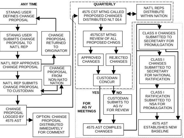
1. This Allied Engineering Documentation Publication (AEDP) by the NATO NADSI Custodial Support Team (CST) in response to user community requests for
implementation guidance, related test plan and configuration management plan of STANAG 4575.
2. Questions or comments should be directed to the Custodian for this document.
Custodian, AEDP-6
Lt. Col. Dennis Caron, USAF
SAF AQIZ
1060 Air Force Pentagon Washington, DC 20330-1060
United States
Phone: 703-588-6414
FAX: 703-696-4337
AEDP-6 (Edition 1) TABLE OF CONTENTS
NATO LETTER OF
PROMULGATION………....ii
RECORD OF CHANGES ……….………...iii
FORWORD……….………....iv
TABLE OF CONTENTS……….………….v AEDP Overview………1-4 Annex A: Background and Application Scenarios………..A-1 Annex B: Rationale for Interface Selection……….…………B-1 Appendix 1 to Annex B: Example of NADSI File Implement…...…B-1-1 Annex C: Acquisition Guidance………..C-1
Appendix 1 – Specification Template for Acquisition Platform – Advanced Data Storage System Characteristics.………C-1-1
Appendix 2 - Specification Template for Ground Station to Meet NADS
Interface Requirements……….…C-2-1
Annex D : Compliance Test and Certification……….…………D-1 Annex E: Configuration Management Plan……….………E-1 Annex F: Application Notes………..………..F-1 Annex G Glossary………...G-1
v
NATO UNCLASSIFIED
1
ALLIED ENGINEERING DOCUMENTATION PUBLICATION (AEDP-XXX) NATO ADVANCED DATA STORAGE INTERFACE (STANAG 4575)
NADSI IMPLEMENTATION GUIDE
1. NADSI Objectives. The primary objective of the NATO Advanced Data Storage Interface (NADSI) standard (STANAG 4575) is to define a data transfer interface for a Removable Memory Module (RMM), which will download any data to any NATO ground station, within a set of defined constraints.
2. NADSI Philosophy. Conformance with the NADS Interface requirements will allow any compliant ground station to download data from any NADSI compliant data storage removable memory module. Individual files, file segments or the full contents of the memory module can be downloaded using sequences of SCSI Read commands. The NADSI standard relies on existing commercial standards and definitions whenever possible. A straightforward directory and file structure is used, that is specific to the NADSI interface but was created using common techniques.
The NATO NADSI working group defined an interface to allow download and transfer of information at high transfer rates and with a low error rate. Multiple industry and government organizations participated in this development. Since multiple data storage technologies and techniques can be used for the storage media, the interface has been defined to allow all media to be read via this protocol. This allows for wide variation in the implementation of the standard.
3. AEDP SCOPE. This document provides the technical information that was developed during the production of the STANAG and updated with results and lessons learned based on use and testing in subsequent years. This information was identified as important to the acquisition communities of the member Nations, but inappropriate for the STANAG. This information is divided into seven discrete sections, each provided in the Annexes to this AEDP as shown in Figure-1.
Annex A explains the NADSI background and application scenarios. Annex B provides the rationale for the selection of the elements of the interface. Since most aspects of the interface were chosen after considerable discussion, it was appropriate to document that discussion and include it for future reference. Annex C provides specific guidance to the acquisition communities in the form of recommendations for
specifications for the airborne recorder and ground NADS Interface of a reconnaissance or surveillance system. Many of the parameters are important to the operation of the recorder, but do not affect the interface. Annex D includes the Compliance Test and Certification procedures for verifying that a product meets the standard. This Annex has two parts: part one providing the certification information for the airborne equipment, and part two for the ground systems. Annex E includes the configuration management plan for managing the STANAG and this documentation. Annex F provides application notes and lessons learned for advanced memory systems. Finally, Annex G is a global glossary for the entire AEDP.
3
Glossary
Rationale For Standard Acquisition Guidance
Compliance Test & Certification Part 1: Airborne Equipment Part 2: Ground Systems
Application Notes Configuration Mgmt Plan Background & Application Scenarios
A
E
D
P
Annex G Annex F Annex E Annex D Annex C Annex B Annex A Figure-1 AEDP Structure NATO UNCLASSIFIED4. Applicable or Referenced Documents:
AEDP-2 NATO ISR Interoperability Architecture (NIIA)
AEDP-3 Declassification/Sanitization Procedures
ANSI/NCITS TR19-1998 Fibre Channel - Private Loop SCSI Direct Attach (FC-PLDA)
ANSI/NCITS 352-2002 Information Technology - Fibre Channel Physical Interfaces (FC-PI) ANSI/NCITS 373-2003 Information Technology - Fibre Channel Framing and Signaling
Interfaces (FC-FS)
ANSI/NCITS 405-2005 Information Technology - SCSI Block Commands 2(SBC-2)
ANSI/NCITS 408-2005 Information Technology - SCSI-3 Primary Commands 3(SPC-3)
ANSI X3.270-1996 SCSI-III Architecture Model
ANSI X3.272-1996 Information Technology - Fibre Channel Arbitrated Loop (FC-AL)
ANSI X3.269-1996 Information Technology - Fibre Channel Protocol for SCSI (FCP)
DOD 5220.22-M National Industrial Security Program Operating Manual
EIA/RS-422 Electronic Industries Association RS for serial transmissions
IEC 61000-4-2 Testing and measurement techniques for Electrostatic Discharge
immunity test
ISO/IEC 4873 Information technology - ISO 8-bit code for information interchange –
Structure and rules for implementation
ISO/IEC 7498-1 Information Technology – Open System Interconnection – Basic
Reference Model.
ISO/IEC 10641 Information technology - Computer graphics and image processing -
Conformance testing of implementations of graphic standards
ISO/IEC 10646-1-1993 Information Technology - Universal Multiple-Octet Amd 2: 1996
Coded Character Set (UCS) - Part 1: Architecture and Basic Multilingual Plane - Amendment 2: UCS Transformation Format 8
ISO 9001 Quality Assurance in Design, Development, Production
Installation and Servicing
MIL-DTL-24308E Connectors, electrical, rectangular, non-environmental, miniature,
polarized shell, rack and panel, general specification for
MIL-DTL-38999 Connectors, electrical, circular, miniature, high density, quick
disconnect (bayonet, thread, and breech coupling), environmental resistant, removable crimp and hermetic solder contacts, general specification for.
MIL-STD-130 Identification Marking of U.S. Military Property
MIL-HDBK-217F Reliability Prediction of Electronic Equipment
MIL-HDBK-454 Standard General Requirements for Electronic Equipment
MIL-HDBK-740 e Noise Measurement of Shipboard Equipment
MIL-HDBK-5400 Electronic Equipment, Airborne, General Guidelines
MIL-STD-461 Requirements for the Control of Electromagnetic Interference
MIL-STD-704 Aircraft Electrical Power Characteristics
MIL-STD-810 Environmental Engineering Considerations and Laboratory Tests
MIL-STD-882 System Safety
MIL-STD-1472 Human Engineering
MIL-STD-1553 Digital Time Division Command/Response Multiplex Data Bus
5
STANAG 4545 NATO Secondary Imagery Format
STANAG 4559 NATO Standard Imagery Library Interface
STANAG 4575 NATO Advanced Data Storage Interface
STANAG 4607 Ground Moving Target Indication
STANAG 4609 NATO Digital Motion Imagery Standard
STANAG 7023 Air Reconnaissance Imagery Data Architecture
STANAG 7024 Imagery Air Reconnaissance Cassette Tape Recorder Standard
STANAG 7085 Interoperable Data Links For Imaging Systems
ANNEX A
BACKGROUND AND APPLICATION SCENARIOS
1. Background. As ISR systems transitioned to digital sensors, the existing
Standardization Agreements, based on film cameras and tape recorders, no longer defined the necessary interfaces to achieve interoperability. NATO Air Force Armaments Group (NAFAG), Air Group IV undertook a study to develop the NATO ISR Interoperability Architecture (NIIA), which defined the key electronic and physical interfaces needed to achieve interoperability between the forces of the respective nations. This architecture defined the interface between the airborne and ground elements as one element requiring standardization. The standards were developed based on the technologies available at the time. The interface consists of the imagery format, like STANAG 7023 or STANAG 4545, and either a wideband data link (STANAG 7085) and/or wideband digital tape recorder (STANAG 7024). The other key interface defined was the output of the ground station, providing standards for the textual report formats, annotated imagery, and imagery library interface.
As technologies have continued to advance, solid-state memories and hard disk drives became viable as airborne, non-volatile, mass memory systems. The format defined by STANAG 7024 for the tape recorders provided interchange in the form of the removable tape cartridge, but this is not applicable to some newer forms of ISR data storage. Further, as technology continues to advance, other forms of mass storage, including optical disk, optical tape, and holographic techniques, will be developed. Although some may lend themselves to interchange of only the media, there will still be a basic requirement to have interoperability at a higher level. A Removable Memory Module (RMM) of the airborne recorder can be removed from the platform and attached to a ground station to allow download of the ISR data. The interface defined in this STANAG provides a common connection that can be used with this RMM for most technologies.
2. Application Scenarios.
2.1 Levels of Interoperability. In the NATO ISR Interoperability Architecture (NIIA) document AEDP 2, NATO defines four levels or Degrees of interoperability. They are:
1. Degree 1: Unstructured Data Exchange. Involves the exchange of human interpretable unstructured data such as the free text found in operational estimates, analysis and papers.
A-2
2. Degree 2: Structured Data Exchange. Involves the exchange of human interpretable structured data intended for manual and/or automated handling, but requires manual compilation, receipt and/or message dispatch.
3. Degree 3: Seamless Sharing of Data. Involves the automated sharing of data amongst systems based on a common exchange model.
4. Degree 4: Seamless Sharing of Information. An extension of degree 3 to the universal interpretation of information through data processing based on cooperating applications.
It should be noted that the objective of the NIIA is to achieve interoperability at Degree 2, with some specific interfaces achieving Degree 3. Degree 4 can be considered a long-term objective, but it was determined that lower degrees of interoperability should not be delayed in favor of ultimately achieving a higher degree. Degree 2
interoperability is a significant accomplishment, and will provide a high level of capability to NATO and coalition forces. Higher degrees of interoperability will be addressed once Degree 2 is achieved and demonstrated.
2.1.1 Levels of Interoperability for Memory Systems. In evaluating the interface
definitions possible with advanced memory systems, three levels of interoperability were identified. All relate to degree two above, and include operational implications. The highest level of interoperability provides complete cross servicing of the ISR aircraft. That implies that all RMMs have the same form factor (size and shape), and be connected to the recorder in exactly the same fashion using identical interfaces. A unit servicing an aircraft of a different nation would be able to remove the RMM and replace it with a new, completely initialized module so that the aircraft could return to its mission. The used RMM could then be transferred to a ground station for complete exploitation. The middle level of interoperability would provide for only access to the data in an intelligent fashion. When the RMM is removed from the aircraft, it could be connected directly to the ground station and the ISR data could be accessed for download or exploitation within normal reporting timelines. For example, if a file was saved within the RMM that included all of the event marks recorded during a mission, it could be identifiable. This could enable priority targets in these files to be examined first. The lowest level of interoperability would provide only a mass dump of the data. Depending on the amount of data collected during the mission and the transfer capabilities of the ground station, a mass dump of the data could be a lengthy and time consuming process. Only after downloading all of the mission data could the ground station interpret the data and identify where files are located, which files contain which information, and how the data should be exploited.
2.1.2 STANAG Exclusions. It should be noted that this STANAG does not include all elements of a complete interface to exchange and exploit data. The higher levels of the
complete interface, including the format of the stored user data, must be defined in other Agreements (for example, STANAGs 4545 or 7023 for imagery).
2.2 Preferred Approach. In discussions with both operational and developmental
personnel, the middle level interoperability option was selected as the preferred approach for the memory system.
The highest level of interoperability requires that the interface between the RMM and the recorder be precisely defined. This implies that the architecture of all recorders be identical as well. Given that many manufacturers have already developed products and some are already in the field, it would be impossible to require all to adhere to an arbitrarily selected architecture and physical constraints. Further, in some cases, the developers of the ISR systems require that the recorders have some unique attributes and trade-offs in the design, due to needed memory capacity, data rate, environmental
hardening, or a designated size or space for the recorder. If we define a specific form factor for the RMM, then the ISR system developers would be very limited in their ability to fit the recorder to the requirements.
The lowest level of interoperability does provide for complete interchange of the data. However, in order to achieve that interchange, precious time is lost performing the mass dump of the data and possibly much more definition would be required of the ground station capabilities. Requiring the complete transfer of the data into the ground station prior to exploitation would not provide the required data exploitation capability within the time constraints imposed by typical operational requirements.
2.3 File Interpretation. As files are written to the Advanced Data Storage System (ADSS), the directory of the files will be retained in the RMM and can be read through the interface defined by this document. This makes it possible for the ground station to find and recover discrete files. It should be noted, however, that it is not intended that the memory system will have "knowledge" of the information stored in it. This is analogous to a tape recorder being able to play back data from specific portions of the tape based on track set ID, but the recorder doesn't know if the data is directories, infrared, radar, or voice. The ground station will be required to identify the content of the memory and to read from the RMM to download the appropriate portion of the data. The ground station must also be able to interpret the contents of the files.
2.4 Operational Scenarios. It is recognized that the optimal use of advanced ISR data storage technologies will only be achieved when the media is replayed in a unit
specifically designed for that purpose, such as in its companion ground station. In most cases, the ground station defined for operational use with a particular sensor system will include a playback unit designed for the RMMs used in the aircraft. For example, a ISR system using a solid-state recorder in the aircraft will likely provide a playback unit compatible with the solid state RMMs in the appropriate ground station. This will allow
A-4
The third scenario in which this interface can be used is for the direct download
r
n the
sion complete use of the memory system's capabilities. However, there are numerous
occasions when the RMMs may be provided to a different ground station for exploitation of the data. This will require that the secondary ground station be able to access the data. It was accepted by the technical team defining this document that the retrieval would be done using data blocks that have been structured into files in accordance with this STANAG. This provides the ability to use the mission tasking and other information (such as an event mark file) to identify the priority data and download that imagery for immediate exploitation. The requirement for this type of operation is based on three operating scenarios.
The first scenario involves a limited action where coalition forces are operating with limited resources. If more than one nation were to provide ISR capabilities, the deployment could be accomplished using one ground station from one of the nations. The primary sensors associated with that ground station would have full operational capabilities, while the other sensors would be exploited using the interface defined in STANAG 4575. All of the ISR data could be exploited in the single ground station without the need for duplicate capabilities in the theater of operations.
The second scenario involves a larger scale operation. It is assumed that multiple ground stations have been deployed and that an aircraft has diverted to a base other than its main operating location. The aircraft may have diverted due to mechanical problems, battle damage, hostile action at its main operating location, or ground station failure. Use of the interface defined in this document, would allow the ISR data collected to be
rapidly accessed and exploited, limiting the possible mission degradation due to the diversion.
of ISR data while on the flight line. In some cases, portable equipment, conceptually ranging from backpacks to full aerospace ground equipment (AGE) carts or portable connections to local area networks (such as on an aircraft carrier), can be used to
download the data without physically removing the RMMs from the aircraft. When this equipment is available, the data port defined by this standard can be used and no other connection needs to be defined. As such, ground equipment designed to be used with a specific advanced data recorder through the interface defined in this STANAG can be used with any other STANAG-compliant recorder. In this scenario, the RMM should only be powered by the aircraft through the recorder’s normal power interface. Also fo this scenario, only the NADS data/control interface should be used to download data from the RMM, but it is possible that the ADSS was being controlled via its native control interface at the time the NADS interface was to be used. Contention betwee recorder’s native control interface and the NADS interface must be avoided. The ADSS must also be placed in an operational state where its NADS interface is functional. In general it may not be possible to sequence power to the ADSS to enable its normal power-up NADSI discovery process. It is therefore recommended that at the conclu of all airborne recording operations, the ADSS be commanded into a recorder state
e
. Assumptions and Ground Rules
enabling the NADS interface and that all further airborne control communications b suspended. This procedure should be defined in the mission application scenarios.
3 . The basic operation, architecture, physical make-up,
ard. .1 RMM Capability
and required interfaces for the NATO Advanced Data Storage Interface Standard were discussed during the initial working group meetings. The users and manufacturers agreed on the following assumptions and ground rules for development of this stand 3 . The data acquisition recorder will have a removable memory
m
3.2 RMM Port(s)
capability, which incorporates the NADS Interface. This means that either the whole recorder can be treated as an RMM and be easily removed from the acquisition platfor and taken to a ground station for data download, or the recorder will contain one or more RMMs, which can be easily removed from the recorder and taken to a ground station for data download.
. The removable memory portion of the recorder (as defined in 3.1 as
3.3 Interface
above) will have port(s) for data download / control and power, as described in this STANAG for the transfer of data to a ground station. The NADS interface is defined the essential interface between the removable RMM and a NATO ground system. The NADS interface will be capable of interfacing with “flying leads”.
. The STANAG 4575 interface defines the physical connector(s), power he
.4 NADSI Connector Accessibility
requirements, the command set, the data interface (electrical and signal protocol), and t file structure.
3 . The STANAG 4575 interface provides two RMM
te
he
.5 File Recovery
connector options that compliant ground systems must support: 1) A single 50-pin D subminiature connector providing both power and data/control interfaces or 2) Separa military 38999 type connectors for the power and data/control interfaces. Consideration should be given to the installed accessibility of the NADSI connectors for all NADSI operating scenarios (see paragraph 2.4). For RMMs implementing 38999 connectors, t 37-pin power connector may be located to inhibit access when mated to its IU within the aircraft (power safety) as long as it is accessible for operating scenario 2.
3 . File recovery will be possible from the RMM when single or
.6 Parameters Outside Control of the STANAG
multiple channels of independent sensor data are recorded. Files can be randomly accessed from the download port based on directory listings.
3 . The NADSI STANAG does not
nology to be used within the removable RMM.
control the physical size, performance levels, configuration and form factor for the recorder and the removable RMM. Due to the variation in capacity/rate/ cost requirements of the users, the NADSI STANAG also does not specify the tech
A-6
3.7 Data Download Alternatives. A minimum of three alternatives are anticipated for ownload of data from the recorder or RMM. These are: (1) normal operation between
e
a d
an acquisition platform and its normal ground station, (2) removal of the RMM from th acquisition platform and connection via the NADS interface to a “different” ground station and (3) download from the acquisition platform to a “different” ground station through the NADS interface via either an intermediate data storage unit or directly to ground station via cable.
3.7.1 Normal Operation. Normal operation means that an acquisition platform and its ssociated ground station are fully integrated and provide maximum system capability.
d a
This capability is to be achieved in one of two ways and either method allows the groun station to fully meet its operational requirements. The first way is removal of the RMM from the acquisition platform and insertion into the ground station interface unit, which is fully integrated into the ground station. The second way would be transfer of the data to the ground station via either a dedicated cable or a dedicated intermediate storage unit. 3.7.2 Direct Download to Compliant Ground Station. Operation with a STANAG 4575
ompliant ground station will allow transfer of all stored data or download of specific c
files via the NADS interface on the RMM. This allows data download rather than
providing full recorder capability. This download can be accomplished by removal of the RMM and connection to the ground station via the NADS interface.
3.7.3 Download Via Intermediate Media or Cable. The third option is to transfer the ored data via the NADS interface to an intermediate storage unit or to the ground
n
er During Download st
station via NADSI-compliant cable while the recorder is still installed in the acquisitio platform.
3.7.3.1 Pow . When the data is downloaded from the RMM via the ADS interface to a compliant ground station and the RMM remains installed in the
om N
aircraft, recorder power will be supplied by the aircraft, not from an intermediate storage unit or cable. When the RMM is removed from the aircraft, power will be supplied fr the ground station via the NADS interface.
ANNEX B
RATIONALE FOR INTERFACE SELECTION
1. Scope. This Annex provides the rationale for the selections of the various elements of the interface.
2. RMM Intelligence and Internal Processing. Initial discussions focused on the allocation of functions to the elements of a recorder system. It was important to ensure that if a RMM was removed from the platform, the data could be recovered without special processing requirements. This required that processing performed by the recorder that affects the data (e.g. error detection and correction (EDAC), error masking,
compression, or memory management schemes) be transparent to the user. If these functions are part of the application, then the recorder should not change it, but functions and processing provided by the recorder must be removed before the data is transmitted through the interface. This can require intelligence in the removable memory module unit.
Further, although some technology applications would require virtually no processing in a memory unit, the application of multiple technologies to storing easily recoverable data in a common format, also leads to the incorporation of basic processing capability in the RMM. The processing allows data in the RMM to be recovered based on a directory and the associated file structure in the RMM.
3. Rationale for Selecting Fibre Channel Interface. Fibre Channel was selected as the Physical and Signaling Interface after a thorough study of all the viable alternatives and consideration of the application scenarios intended for the use of this STANAG.
3.1 Alternatives Considered. A number of alternatives were examined as candidates for this interface. The first step in this process was to define the criteria for the selection. The criteria selected were the following:
1. Commercial standard (ISO, ANSI) 2. Not proprietary to any single company
3. Standard definition readily available to community
4. Data transfer rate: Current capability of 1 Gbps or better with planned growth by a factor of 2 or better
Because of the wide selection of possible candidates, a matrix of options was created and reviewed. The complete matrix included 17 different candidate protocols with 16 different parameters on each. A selection of the primary candidates is shown in Table B-1.
B-2 TABLE B-1
Candidate Protocols For NADSI (August 1999)
Protocol Data Rates Connections
SCSI Wide Ultra3 1.28 Gbps 68 wide parallel,
80 pin connector
SCSI Wide Ultra3 640 Mbps 68 wide parallel,
80 pin connector
SCSI Wide Ultra3 320 Mbps 68 wide parallel,
80 pin connector
SCSI Fast and Wide 160 Mbps 68 wide parallel,
80 pin connector
USB 12 Mbps 4 pin serial
Fibre Channel 100 Mbps – 4 Gbps CAT5 T.P., fibre, or coax
serial
Firewire 400 – 800 Mbps 6 pin serial
Ethernet 1.25 Gbps CAT5 T.P. serial
ATM 622 Mbps – 2.48 Gbps Copper, fibre
PCI 1 Gbps 120 pin parallel
SSA 640 Mbps 4 pin serial
HIPPI 6400 6.4 Gbps 20 wide copper,
10 wide fibre
3.2 Fibre Channel Selection. Fibre Channel was chosen because of a desire to use an industry standard interface, rather than developing a new custom interface or adopting an existing proprietary interface. Fibre Channel is already widely accepted for similar applications (rapid movements of large amounts of data) and several contributing vendors already have relevant experience.
The base Fibre Channel standards contain multiple options. There are some features that are mandatory, while others are optional. In addition, there are optional ways of implementing features; for example one can choose electrical or optical
transmission media, different signaling rates, etc. So by themselves, the base standards do not ensure interoperability. The Fibre Channel community approaches the
interoperability issue by developing profiles that tend to follow market areas. The most active market area is the storage industry. There are three main Fibre Channel
interoperability documents for storage as listed below.
1. FC-PLDA FIBRE CHANNEL PRIVATE LOOP SCSI DIRECT ATTACH [NCITS TR 19:1998]
. FC-TAPE FIBRE CHANNEL TAPE AND TAPE MEDIUM CHANGERS
r SCSI
to the preferable to developing new custom requirement specifications. Most, if not all,
comme
d
t
. are needed in the future, copper to ber adapter modules are commercially available. The rationale behind connector selectio
y at the application level. If needed, data encryption and/or compression should be performed independent of and transparent to the STANAG 4575 interface requirements.
2. FC-FLA FIBRE CHANNEL FABRIC LOOP ATTACHMENT [NCITS TR 20:1998]
3
[in approval]
The NADSI Technical Support Team chose the FC-PLDA profile because of its flexibility and because it is optimized for the Small Computer System Interface (SCSI) as the command set that uses Fibre Channel as a transport mechanism. ANSI developed the FC-PLDA profile by selecting options from the FC-FCP Fibre Channel Protocol fo [ANSI X3.269-1996], FC-AL Fibre Channel Arbitrated Loop [ANSI X3.272-1996], and the SCSI-3 architecture model [ANSI X3.270-1996]. SCSI –3 was selected as the
command protocol for this NADSI standard because it is well suited to large file transfers and most of the contributing vendors have existing experience with SCSI. The Fibre Channel PLDA specification provides implementation details for mapping SCSI on Fibre Channel interface. Use of these existing, commercially accepted documents is
rcially available FC chips and adapter boards support the FC-PLDA profile. These profiles typically do not specify the lowest physical level of behavior, so the selection of signaling rates, media type (optical or electrical and variants thereof), an connectors must also be made in order to ensure interoperability. A 1 Gbps signaling rate was initially selected because it was the fastest speed available at the time (200-2001), but with the promulgation of Edition 3 of the STANAG that rate was changed to 2Gbps. Copper cable was chosen instead of optical fiber because reliable copper connections tha run at 2 Gbps are available. Optical fiber is more difficult to work with, and optical fiber connectors are not yet well suited to frequent mate-demate cycles, especially in harsh environments. The main advantage of optical cable is for extended length connections At 2 Gbps, copper provides a 10-meter run length, which is considered more than adequate for this application. If longer run lengths
fi
n is described in section 6.0 of this Annex.
It should be noted that the FC-3 level in the Fibre Channel protocol defines common services that may be available across multiple ports in a network. These include mandatory services such as "Login Server" but they also include optional services such as "Data Compression" and "Encryption" which are prohibited in the NADSI STANAG and should be avoided in selecting services for the FC-3 level. However, this in no wa prevents the system from using encryption or compression
B-4 4. Rationale for the STANAG 4575 SCSI Control Protocol. Fibre Channel has been selected as a well-defined, high-speed interface best suited for rapid download of ISR mission data from a removable memory cartridge via a simple connection. Fibre Channel supports a number of mapping layer (FC-4) protocols including SCSI, IPI, HIPPI, LE and SBCCS. Of these, the SCSI protocols are the most widely used in computer peripheral storage devices. The Fibre Channel Private Loop SCSI Direct Attach (FC-PLDA, ANSI NCITS TR19-1998) interoperability profile has been selected as a requirement document for STANAG 4575. Table 17 of the FC-PLDA document specifies a control protocol using a subset of SCSI-3 commands, features and parameters for SCSI Disk and Controller Devices. FC-PLDA defines SCSI command, feature and parameter usage categories of “Required”, “Allowed”, “Invokable” and “Prohibited” between the SCSI Initiator and its Target. FC-PLDA Table 17 definitions assume that the Target device is a magnetic disk drive or equivalent device.
The STANAG 4575 control protocol must support a number of data storage media technologies. Therefore the usage definitions of FC-PLDA Table 17 have been redefined for STANAG 4575. Only the minimum set of SCSI commands required to download ISR mission data from the memory cartridge are defined as “Required”. These five STANAG 4575 “Required” SCSI commands are:
1. Test Unit Ready 2. Inquiry
3. Read Capacity
4. Read (10) Logical Block 5. Request Sense
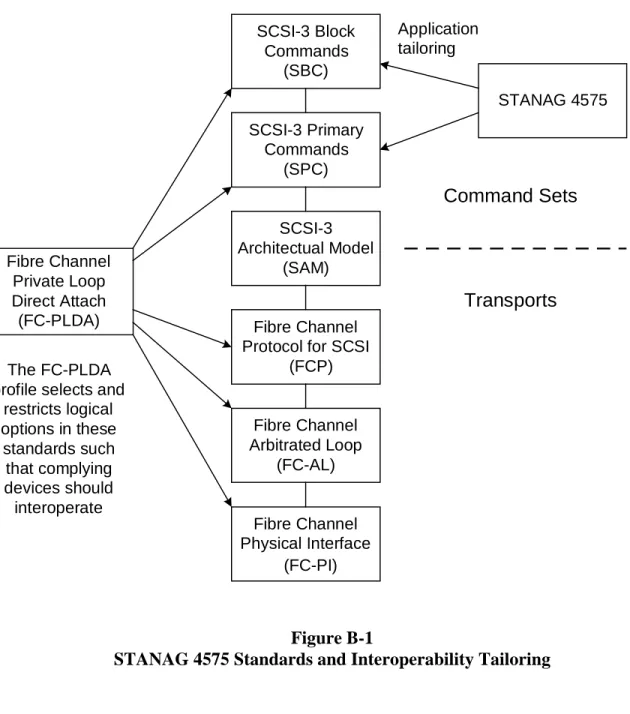
Figure B-1 illustrates the selected standards, how the FC-PLDA profile selects and restricts logical options in these standards to achieve interoperability and how STANAG 4575 further tailors the “Required” SCSI command set.
In addition, it is recognized that some applications will be required to write to the RMM as well. Initially for Editions 1 and 2 of the STANAG, commands required to format and/or write to an RMM were defined as “Recommended”. Those commands were not required for any STANAG 4575 RMM implementation. However, it was recommended that if the functions were incorporated into an application, the “Recommended” commands should be used to preclude a proliferation of unique commands. All other “Required” FC-PLDA SCSI commands, features and parameters not defined as “Required” or “Recommended” for STANAG4575, were (and still are) redefined as “Allowed” such that they may be implemented as appropriate. Table B-1 in Editions 1 and 2 of the STANAG provided the five “Required” STANAG 4575 SCSI commands and two “Recommended” commands and their features and parameter usage definitions. However in 2008, based on testing results, it was determined that the
Recommended “Write” commands were actually in conflict with the NADSI format and it was decided to delete those commands in Edition 3 of the STANAG. Note: For more details see section 6.0 of Annex F on page F-4 in this document.
Fibre Channel Physical Interface (FC-PI) Fibre Channel Arbitrated Loop (FC-AL) Fibre Channel Private Loop Direct Attach (FC-PLDA) SCSI-3 Block Commands (SBC) SCSI-3 Primary Commands (SPC) SCSI-3 Architectual Model (SAM) Fibre Channel Protocol for SCSI
(FCP)
Transports Command Sets
The FC-PLDA profile selects and
restricts logical options in these standards such that complying devices should interoperate STANAG 4575 Application tailoring Figure B-1
STANAG 4575 Standards and Interoperability Tailoring
Figure B-2 shows an example STANAG 4575 mission data download command sequence following application of power to the compliant Memory Cartridge.
B-6 T e s t U n i t R e a d y SCSI Op Code 0x00 I n q u i r y S C S I O p C o d e 0 x 1 2 R e a d C a p a c i t y SCSI Op Code 0x25 R e t u r n S t a t u s = G o o d R e t u r n I n q u i r y D a t a R e t u r n B l o c k S i z e a n d A d d r e s s o f L a s t B l o c k R e a d L o g i c a l B l o c k 1 , 1 ( R e a d 1 B l o c k S t a r t i n g a t Ad d r e s s 1 ) S C S I O p C o d e 0 x 2 8 R e t u r n S T AN AG D i r e c t o r y R e a d L o g i c a l B l o c k M , N ( R e a d M B l o c k s S t a r t i n g a t Ad d r e s s N ) S C S I O p C o d e 0 x 2 8 R e a d L o g i c a l B l o c k P , Q ( R e a d P B l o c k s S t a r t i n g a t Ad d r e s s Q ) S C S I O p C o d e 0 x 2 8 R e t u r n R e q u e s t e d M i s s i o n D a t a R e t u r n R e q u e s t e d M i s s i o n D a t a
Host Controller
Recorder
Figure B-2Example STANAG 4575 Mission Data Download Command Sequence
st
CSI e
SI compliant devices ust have a method of indicating unsupported or illegal commands.
a to
. then the host can safely issue the corresponding mandatory SPC and SBC commands.
Example Illustrating a Recorder’s Response to an Unsupported SCSI Command Figure B-3 shows an example of a command sequence where the NADSI Ho Controller issues a command not supported by the Memory Cartridge and how the Memory Cartridge responds using protocols defined by the SCSI-3 Architecture Model. (SAM). The SCSI-3 Architecture Model (SAM) defines SCSI status codes and Initiator-Peripheral protocols to be used when the peripheral receives unsupported or illegal S commands. These protocols require the Peripheral to respond to an unsupported or illegal command with a CHECK CONDITION status and to subsequently respond to th Initiator’s Request Sense command with appropriate SENSE KEY and SENSE CODE information. Since it is anticipated that ground download facilities will issue SCSI commands other than just those “required” by STANAG 4575, NAD
m
NADSI compliant recorders, as a result of STANAG 4575 tailoring to the SCSI SPC and SBC mandatory command sets, may respond to the Inquiry command with 00h SCSI Version code and the ground/shipboard NADSI host must be prepared accept this response and restrict SCSI commands issued to the STANAG 4575
mandatory set. RMM support for STANAG 4575 defined “Allowed” commands can be determined by the host and the SAM defined Check Condition/Request Sense protocols If an RMM responds to an Inquiry command with a specific SCSI version compliance,
SCSI Command not
supported by Recorder Return Status =
Check Condition
Sense Key = Illegal Request
Sense Code = Invalid Command Operation
Code Request Sense
SCSI Op Code 0x03
Host Controller
Recorder
B-8 5. Rationale for Chosen File System Implementation. The recommended File System for the STANAG 4575 is unique but quite simple. It is flexible enough that it can be
implemented in any media type. The file system provides a single directory that contains basic information about each recorded file and also contains pointers to the beginning of each file and block count for each file. The files described by the directory are the containers for all other recorded data. No assumptions are made regarding the contents of the files, any content and structure is permitted. Each file is required to be contained within strictly sequential logical memory locations.
5.1 Alternatives Considered. Commercial and modified commercial alternatives were considered in order to meet the needs of both embedded airborne files structures as well as the ground stations that may use commercial file structures.
5.1.1 Commercial Alternatives. Existing commercial file systems were examined for their suitability for this application. These included (but were not limited to):
5.1.1.1 UDF (CD-ROM and DVD file format). UDF is a new format, now used for recording data on CD-ROM and DVD media. Software was not available to write data in this format for any of the available embedded operating systems likely to be used by recorders. Software was likely to be available to read this file system in many
commercial operating systems used at ground stations. Its complexity was judged too difficult at this time to implement for most acquisition systems. There was concern about the actual commercial support for media block sizes other than 2K. This was important; especially for some of the media types that require large media block sizes.
5.1.1.2 ISO-9660 (CD-ROM file format). ISO-9660, with its various extensions, is the standard format used for recording data on CD-ROM media. Software was likely to be available to read this file system in all commercial operating systems used at ground stations. The ISO-9660 file system’s complexity was judged too difficult to implement by most of the recorder vendors. There was also a concern with this file system about actual support for various media block sizes.
5.1.1.3 NTFS (Microsoft Windows NT File System). The NTFS has attractive fault tolerance features, and permits very large files and a very large total address space. Its design is proprietary and it is judged to be very difficult to implement in the commonly used embedded operating systems used by many recorders. Multiple versions of NTFS have been released by Microsoft, and they are not necessarily compatible with each other. Thus broad compatibility with the installed base of NT workstations cannot be assured.
5.1.1.4 FAT (Microsoft Windows File System). FAT –16 was immediately rejected due to its file size limitations. FAT-32 is supported by both embedded and workstation operating systems. The total data permitted to be stored is large, however a single file is
limited to a maximum of 4 gigabytes. This would require very large files to be broken down into multiple files. Common implementations are not optimized for very high-speed transfers and some modifications or tests would be required of existing systems. 5.1.1.5 XFS (Silicon Graphics File System). The XFS file system is widely regarded as extremely high performance, with regard to sustainable data rates and file sizes and total file system sizes. It is being placed into the public domain by SGI for use by Linux based systems. Unfortunately the file system is quite complex. The source code released to date is tens of thousands of lines of code. Understanding and porting the relevant
portions of this code to embedded systems was considered a prohibitively expensive task. Only SGI workstations support this file system at this time.
5.1.2 Modified Commercial Alternatives. The option to modify an existing standard was also considered. These were considered because of the diverse architectures available with advanced memory systems. The options examined include:
5.1.2.1 Logically Sequential Access Mode. A very simple approach of placing all data in logically sequential files was proposed from within the group. Code would need to be developed by both the recorder and ground segment devices to access data in this format. Although new code would need to be developed by all parties, its implementation is expected to be quite simple.
5.1.2.2 Hybrid Sequential/Random Access Mode. A more complex approach was proposed that allowed for alternate means of addressing data. The data would be permitted to be placed either strictly sequentially (as preferred by solid state recorder vendors) or to be placed interleaved with other data (as preferred by rotating disk recorder vendors). This proposal also provided for multiple volumes or partitions (with their individual directories) to be defined within one physical media and for one volume to be constructed from multiple physical media. Although simple to implement for the recorders, this is complex to implement for the ground segments.
5.2 Conclusion. The two modified commercial alternatives developed widely polarized positions within the industry participants. There was no compromise position developed to bridge these views. The government participants concluded that no common solution was going to be developed. In a government-only session, an agreement was reached to ensure that the interface was as simple as possible and that the interface places the minimum burden on the ground station. The “Logically Sequential Access Mode” approach was selected as the file system to be used for this STANAG.
An example of the chosen NADSI approach is provided in Appendix 1 to this Annex for four sample files to be stored in a file system with an arbitrary block size of 300 bytes. This will allow a maximum of two file entries per directory block, given the size of the Directory block and File entries provided in the STANAG (Figures B-2 and B-3).
B-10
6. Physical and Power Interface Selection Rationale. The rationale used in selecting the connectors and power is discussed in this section. The choices made in this
determination were primarily based on the STANAG 4575 Interface Requirements as provided below.
Primary consideration in connector selection was given to the D-sub connectors and MIL-STD-38999 round twist-lock military connectors. Of these, the D-sub
connectors were commonly available, proven with Fibre Channel, lower cost, and had been used successfully in an aircraft environment. However, some applications in pods, aircraft and on the flight line will require MIL twist lock connectors in order to meet requirements for grounding, EMI, RFI, environmental covers and other considerations. Therefore, the standard will include provisions for both styles so that the acquisition office responsible for a particular application can choose between the most rugged or the lower cost. The ground station must support both connector types. The use of adapter cables or multiple cable sets is anticipated.
The original power (both voltages and the associated currents) was estimated by the manufacturers for all anticipated RMMs. The working group reviewed this data and a worse case set of voltages and currents was compiled. Subsequently, this list was reviewed and revised downward to the current STANAG requirement.
6.1 STANAG 4575 Interface Requirements. The interface was based on the following requirements:
1. Support the 3 operational scenarios for data download
2. Maintain Fibre Channel signal integrity and impedance control 3. Provide regulated, noise-free secondary power voltages to the RMM
4. Meet applicable EMI/EMC requirements in the NATO Processing Facility and on the Flight Line when the STANAG 4575 interface is connected
5. Meet applicable EMI/EMC requirements within the acquisition platform when the STANAG 4575 interface is not connected (captive EMI/dust connector cover)
6. Provide an environmental seal on the RMM
7. Provide an easy and secure connection (connector retention mechanism) 6.2 Connector Considerations.
6.2.1 Connector Characteristics Considered. The specific characteristics of the connectors that were of concern are as follows:
1. Physical Characteristics: a. Size and Mounting
b. Environmental Qualifications/Hermetic Seal/Corrosion Resistance c. Covers, caps and seals
d. Retention and Release
B-12 f. Mate/De-mate Cycles
g. Carrier Deck Operations 2. Electrical Characteristics:
a. Copper versus Fibre connections b. Converters and Adapters available c. Voltage/Current and Sense Requirements d. Grounding, Bonding and Shielding e. EMI/EMC
3. Practical Application Characteristics: a. Availability and Cost
b. Repair ability
c. Commercial Standards
6.2.2 Specific Connector Considerations. Areas of emphasis are highlighted below. 6.2.2.1 Fibre Channel Performance. The requirement for simultaneously maintaining Fibre Channel signal integrity and impedance control plus providing noise-free power in a common interface was thoroughly analyzed during the development of the STANAG. Gigabit Fibre Channel has bit cells less than one nanosecond in width. Fibre Channel relies on high signal integrity interconnect and provides no embedded Forward Error Correction (FEC) mechanisms. Users are specifying recorders with Bit Error Rates better than 10-12. This level of performance will not be met if the download interface introduces data errors. At its 2Gbps data rate, Fibre Channel can also be a very significant noise radiator.
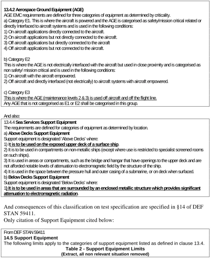
6.2.2.2 EMI/EMC Considerations. EMI/EMC must be taken into consideration for all three configurations of the RMM, including the case where cables are attached to the RMM in the acquisition platform. EMC standards such as MIL-STD-461 (US) or DEF STAN 5941 (UK) are typically invoked in these applications. The various EMC
standards available require a range of conducted and radiated emission and susceptibility testing and typically specify that testing must simulate actual installation and usage, e.g., shielded cables or shielded leads (including power leads and wire grounds) within cables should be used only if they have been specified in installation requirements. Cables should be checked against installation requirements to verify proper construction
techniques such as use of twisted pairs, shielding, and shield terminations. Details on the cable construction used for testing must be included in the EMI Test Procedure (EMITP). In the case of the single 50-pin connector, it was thought that the CE and RE tests may be difficult to pass with expected out-of-specification energy at the Fibre Channel baud rate and at the power supply switching frequency and its harmonics. The two-connector approach was considered in order to resolve this issue and to provide an alternative connection method when necessary. Testing of the 50-pin connector and cable is required in order to identify and resolve any EMI/EMC issues.
NATO UNCLASSIFIED
Another issue considered was that conducted susceptibility testing as described in MIL-STD-461 and other EMC standards include subjecting the unit’s power lines to tests
which inject voltage/current spikes, pulses and damped sine wave waveforms. Passing some of these tests requires the use of protection devices that are not considered
appropriate for secondary input voltages such as 3.3VDC and therefore, those tests may not apply to all the NADS power interface applications. However, since Mil-STD 461-E (Appendix) requires that all interfaces be tested, alternate means for providing protection to those circuits must be found or revised test requirements must be addressed.
6.2.2.3 Connectors/Cables Considered. Various MIL and Commercial connectors were considered for use. The RMM is expected to blind mate into its housing, therefore both blind mate and other mounts were considered. MIL connectors and the associated connectors are invariably a high cost alternative to standard computer type connectors and cables. Data transfer during download is expected to be 1 to 2 Gigabits per second, which will require high integrity of the signal path including the connector chosen. Naval Air Warfare Center Weapons Division (NAWCWD) at China Lake investigated Fibre Channel connector use in Navy aircraft systems and found that both D-Sub and MIL Circular connectors were being used. They provided available test data and flight experience to the working group. In the selection of connector type, both fibre optic and copper connectors are defined for the Fibre Channel interface and each was considered in the selection process.
6.2.3 D-sub connector Considerations. The use of D-sub connectors was strongly desired by some members of the working group, based on size, expense and availability. However, a significant number of questions were raised concerning their physical and performance characteristics. A number of commercial and military users had test data and good experience with both 9 pin D-sub and other low pin count D-sub connectors. However, a single 50 pin D-Sub connector was being considered in order to support both the signal and power requirements for NADSI. A summary of the trade-offs between the single and two connector approach is provided in 6.2.3.3. Test data for the 50 pin D-sub connector with acceptable gigabit rate Fibre Channel performance was not available at the time. A number of groups agreed to technically investigate its performance, perform testing and report to the TST.
6.2.3.1 D-sub Connector Testing. The following specific tests and investigations were performed to determine adequacy of the D-sub connector:
1. One of the test groups at Naval Air Warfare Center Aircraft Division (NAWCAD) at Pax River had been investigating Fiber channel copper
connections. They provided a test demonstration of the D-sub 9-pin connector with camera data. The 9-pin D-sub connector was clearly adequate for 1 Gbit data transmission.
2. NAWCWD China Lake provided some preliminary test reports in conjunction with Raytheon testing.
3. General Dynamics Advanced Information Systems (GDAIS) tests of the 50-pin D-sub connector showed acceptable performance with no power supply voltages applied.
B-14 4. Miltope EMI/EMC Tests of Dec 1999- Miltope passed EMI (MIL-STD-461C
)on the Raytheon Mass Storage Unit that contained four cartridges and each cartridge was configured with a 50-pin D-sub I/O connector for power and data. The test data was provided to the TST at the March 01 meeting.
6.2.3.2 Locking Mechanisms for D-sub connectors. In the case where a D-sub connector is used for download on the flight line, a locking mechanism is required. Multiple
locking methods were evaluated and the Positronics Corporation approach was
determined to be the best. Documentation, part numbers and permission to specify the connectors based on ANSI Policies and Guidelines were obtained from Positronics Corporation.
6.2.3.3 Use of one D-sub connector for power and signal vs. two connectors. Although the 9 pin D-sub connectors were proven for both signal and power applications, meeting the power requirements for all RMMs would require a minimum of a 37-pin power connector. The use of a 9 pin and a 37-pin connector would have used much more space on the RMM than a single connector. The expense for two connectors, covers and locking mechanisms was contrary to the philosophy of minimum cost and size when using the D-sub connectors. The single 50-pin D-sub connector was seen as the best alternative.
6.2.3.4 Power/signal distribution for the D-sub connector. The power connections in the 50-pin D-sub connector are in the center with the signal connections at the ends. This allows separation of the input and output high data rate signals and optimum distribution of the power connections. The number of pins allocated to each voltage is dependent on the maximum required current for each voltage. Sense wires for each voltage are
incorporated and additional pins are reserved.
6.2.3.5 Mate/Demate Cycles. The specified number of mate/demate cycles was
investigated for the 50 pin D-Sub connector, to insure that it would be able to support a reliable connection to the ground stations over a long life. The socket connection is the primary factor controlling the number of mate-demate cycles of the connector set. The 50 pin connectors that were defined in the STANAG had a minimum mate-demate cycle specification in excess of 10,000. This was greater than the estimated number of cycles over the life of the RMM.
6.2.4 MIL-Circular Connector Considerations. A number of applications will require a MIL qualified connector for the NADS interface. The working group determined that both the D-sub and MIL connectors will be allowable on the RMM and that the ground stations will provide the adapter such that either version can be connected to the system. 6.2.4.1 Use of two MIL-Circular connectors for power and signal. In order to preserve the maximum performance and allow for the highest potential currents in the power connector, separate connectors for power and signal were chosen for the case where MIL
connectors are required.
6.2.4.2 Investigation into MIL-Circular twist lock connectors. A number of circular MIL-DTL-38999 connectors were considered and test data was investigated. A non-shielded multi-pin connector could be used for the copper Fibre Channel connection, however, it was questioned if this configuration would meet crosstalk, EMI, RFI and bandwidth requirements. Test data were provided on the W.L. Gore & Associates, Inc. inserts for the size 11 shell MIL circular connectors that showed the best bandwidth and least interference performance in a shielded Fiber Channel connector. The
four-connection configuration allows for a balanced and shielded data input and output. A separate MIL-DTL-38999 connector was chosen for use as the power input. The power connector will separate the effects of the power supply/connection from the signal I/O while allowing maximum current for all voltages used.
6.3 Aircraft Power Availability and Power Safety Interlocks. Members of the working group investigated the potential effects of an inadvertent connection to both the aircraft power and ground support equipment (GSE) power while downloading data from the RMM. Multiple interlock methods, both active and passive, were suggested. Each method increased the complexity of the RMM interface for the connector and ground station. No simple method was foolproof. The working group questioned the need for GSE power and the CONOPS that governed aircraft power. The country POCs
investigated the availability of acquisition platform power during download of the RMM while installed in the acquisition platform and determined that power would be available in every case. It was therefore agreed by all members that power will not be applied by the GSE for data download of the RMM while the RMM is in the acquisition platform. 6.4 STANAG Selections. The STANAG provides for two alternate configurations for the signal and power connections to the RMM. The D-Sub connector with 50 pins is the low cost, small size option that is primarily intended for use on small, commercial, or low cost RMMs. The circular military connectors, such as with the W.L. Gore & Associates, Inc. (or equivalent) insert and cable, is intended for harsh environment (fighter/pod) use where circular military specifications are required. It also provides options for use in specific applications or operating scenarios.
6.4.1 D-sub Military Connector. A 50 contact male D-sub (pin contacts), Amp P/N 746790-1 or equivalent, may be utilized on the RMM for the signal and power interface. The pin assignments are provided in the STANAG and the quantity of pins supports the required currents. In applications requiring a positive locking mechanism, a Positronic Corporation 50 contact male D-sub connector, part number HDC50M32S0V30 (non-hermetic), SAVAC50M ((non-hermetic), or equivalent will be utilized. The mating cable will utilize a 50 contact female D-sub connector, Amp P/N M24308/2-346F (solder) or T&B P/N 622-50S (mass terminated) or equivalent, with the Positronic Corporation 50 contact female D-sub connector with quick release locking mechanism and EMI backshell, part
B-16 number RD50F10GVL0 (non-hermetic), SAVAC50F (hermetic), or equivalent for the applications requiring a positive locking mechanism. In no case will a connector use fittings that would preclude mating with the positive locking mechanism defined above.
Figure B-4 provides a drawing of a typical STANAG 4575 cable assembly using the 50 Pin D-sub Military mating connector for the RMM side (J2) and an HSSDC connector (J1) for the Ground Station (GS) side of the cable assembly. It is important to note the required pin-out descriptions for the connections between J1 and J2, that is: Tx- on the GS side must go to Rx- on the RMM side. Similarly, Tx+ on the GS side must go to Rx+ on the RMM side. The same pattern must be applied to the other 2-wire set of connections in the cable assembly.
Figure B-4
Typical STANAG 4575 Cable Assembly using the 50 Pin D-sub Mil Connector
NATO UNCLASSIFIED
6.4.2 Circular Military Connectors. Two connectors were chosen for use in this configuration, one for the data, and one to provide power. A chassis mount connector,
part number W.L. Gore & Associates, Inc. FCN 1058 or FCN 1060, or equivalent is used for the data in this configuration of the interface. (Note - The Amphenol connector, TV06RW-11-54P, is listed as an equivalent connector and has been used successfully for this application.) The mating cable utilizes the W.L. Gore & Associates, Inc. FCN 1059 connector or equivalent. A chassis mount connector, part number
MIL-DTL-38999/20WD35SN, or equivalent, is used for the power in this configuration of the interface. The mating cable uses the MIL-DTL-38999/26WD35PN connector, or equivalent.
Figure B-5 provides a drawing of a typical STANAG 4575 cable assembly using the Circular Military FCN-1509N mating connector for the RMM side (J4) and an HSSDC2 connector (J3) for the Ground Station (GS) side of the cable assembly. It is important to note the required pin-out descriptions for the connections between J3 and J4, that is: Tx- on the GS side must go to Rx- on the RMM side. Similarly, Tx+ on the GS side must go to Rx+ on the RMM side. The same pattern must be applied to the other 2-wire set of connections in the cable assembly.
Figure B-5
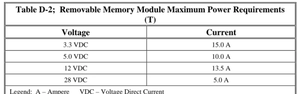
Typical STANAG 4575 Cable Assembly using the Circular Mil. Connector 6.4.3 Power Connector and Pin Assignments. The Power Interface for the STANAG 4575 port will be implemented in the RMM for the chosen connector configurations. The voltage, currents and power pin definitions are specified in the STANAG, for each
connector configuration. Power supply regulation is required to be +/- 5% for 3.3, 5.0, and 12 VDC, and +/- 10% for 28 VDC. These values were set, based on expected operation of known RMMs in a controlled environment such as a ground station, by the manufacturers in the working group.
6.4.4 Power Availability Policy. There are two scenarios that were considered in determining the power availability policy. The first scenario involves removal of the RMM from the acquisition platform and transportation to a ground facility to process the
B-18 collected mission data. In that scenario the RMM will be powered through the STANAG 4575 power interface.
In the second scenario, the RMM remains on the acquisition platform, mounted within its native Interface Unit (IU). In that scenario the RMM will be powered via acquisition platform power only, using the recorder’s native power supply located within its IU. The STANAG does not define or require RMM power protection logic for the potentially damaging case of both acquisition platform and STANAG power being simultaneously applied to the RMM. Power should never be applied by the download equipment in this scenario. This determination was based on an investigation regarding all participating countries into availability of acquisition platform power for data
download after a mission.
APPENDIX 1 to ANNEX B
EXAMPLE OF NADSI FILE IMPLEMENTATION.
1. Example description. This appendix describes an example of the NADSI
implementation for the storage of four files in NADSI block 1 and block 2 in terms of the hexadecimal and decimal representation for the file structure. The assumption is a block size of 300 bytes, which would mean that a maximum of two file entries per directory block is possible (64bytes + 112 + 112 = 288 bytes). The spread sheet has 600 lines, representing the 2 x 300 byte blocks. Each line is a byte, with both the hex and decimal representation of which byte should be there. It can be assumed (as per the STANAG) that multiple byte numbers are stored with their MSB in the first memory address and with their LSB in the last memory address. Strings are represented as Left Justified, and are terminated with the ASCI 0x00 NULL character (EOS – End Of String). The file size parameter assumes that the file occupies the whole of each block, hence the total is a multiple of 300. This is perhaps unlikely in a real world scenario, but was made simple for the example.
Filename : NADSITESTFILEalpha
File Size
:
70,500,000 Bytes File Start Address : 100 decFile Block Count : 235,000 dec File Create Date : 02 Oct 2002 File Create Time : 13:04:27.00
Filename : NADSITESTFILEbravo
File Size : 151,310,100 Bytes File Start Address : 236,000 dec File Block Count : 504,367 dec File Create Date : 02 Oct 2002 File Create Time : 17:07:15.03
Filename : NADSITESTFILEcharlie
File Size : 47,220,000 bytes File Start Address : 741,000 dec File Block Count : 157,400 dec File Create Date : 03 Oct 2002 File Create Time : 08:09:59.07
Filename : NADSITESTFILEdelta
File Size : 419,346,300 bytes File Start Address : 899,000 dec File Block Count : 1,397,821 dec
B-1-2 * File Create Date : 03 Oct ----
* File Create Time : 09:59:----
* Note: The year and the seconds are not defined in the fourth file to show an example of how the file system should work when portions of the field are unavailable.
2. NADSI Block Layout. The layout for NADSI blocks 1 and 2 is provided below for the four files described above.
NADS Block 1 & 2 Layout for 4 files (a,b,c,d) with a block size of 300 bytes
Byte Element
Number Element Byte File HEX DEC
(1-600) Number 1 Magic Number (8) 1 46 70 "F" 2 2 4F 79 "O" 3 3 52 82 "R" 4 4 54 84 "T" 5 5 59 89 "Y" 6 6 74 116 "t" 7 7 77 119 "w" 8 8 6F 111 "o"
9 Revision Number (1) 1 01 1 Edition 1
10 Shutdown (1) 1 FF 255 Good
11
Number of File Entries
(2) 1 00 0 2 files 12 2 02 2 13 Reserved (4) 1 FF 255 14 2 FF 255 15 3 FF 255 16 4 FF 255 17 Volume Name (32) 1 4E 78 "N" 18 2 41 65 "A" 19 3 44 68 "D" 20 4 53 83 "S" 21 5 54 84 "T" 22 6 45 69 "E" 23 7 53 83 "S" 24 8 54 84 "T" NATO UNCLASSIFIED
25 9 52 82 "R" 26 10 4D 77 "M" 27 11 4D 77 "M" 28 12 31 49 "1" 29 13 00 0 EOS Null 30 14 00 0 EOS Null 31 15 00 0 EOS Null 32 16 00 0 EOS Null 33 17 00 0 EOS Null 34 18 00 0 EOS Null 35 19 00 0 EOS Null 36 20 00 0 EOS Null 37 21 00 0 EOS Null 38 22 00 0 EOS Null 39 23 00 0 EOS Null 40 24 00 0 EOS Null 41 25 00 0 EOS Null 42 26 00 0 EOS Null 43 27 00 0 EOS Null 44 28 00 0 EOS Null 45 29 00 0 EOS Null 46 30 00 0 EOS Null 47 31 00 0 EOS Null 48 32 00 0 EOS Null 49
Forward Directory Link
(8) 1 00 0
50 Block 2 2 00 0
51 "Next Directory Block" 3 00 0
52 4 00 0 53 5 00 0 54 6 00 0 55 7 00 0 56 8 02 2 57
Reverse Directory Link
(8) 1 00 0 58 Block 1 2 00 0 59 "This Block" 3 00 0 60 4 00 0 61 5 00 0 62 6 00 0 63 7 00 0
B-1-4 64 8 01 1 65 File Name (56) 1 a 4E 78 "N" 66 2 a 41 65 "A" 67 3 a 44 68 "D" 68 4 a 53 83 "S" 69 5 a 54 84 "T" 70 6 a 45 69 "E" 71 7 a 53 83 "S" 72 8 a 54 84 "T" 73 9 a 46 70 "F" 74 10 a 49 73 "I" 75 11 a 4C 76 "L" 76 12 a 45 69 "E" 77 13 a 61 97 "a" 78 14 a 6C 108 "l" 79 15 a 70 112 "p" 80 16 a 68 104 "h" 81 17 a 61 97 "a" 82 18 a 00 0 EOS Null 83 19 a 00 0 EOS Null 84 20 a 00 0 EOS Null 85 21 a 00 0 EOS Null 86 22 a 00 0 EOS Null 87 23 a 00 0 EOS Null 88 24 a 00 0 EOS Null 89 25 a 00 0 EOS Null 90 26 a 00 0 EOS Null 91 27 a 00 0 EOS Null 92 28 a 00 0 EOS Null 93 29 a 00 0 EOS Null 94 30 a 00 0 EOS Null 95 31 a 00 0 EOS Null 96 32 a 00 0 EOS Null 97 33 a 00 0 EOS Null 98 34 a 00 0 EOS Null 99 35 a 00 0 EOS Null 100 36 a 00 0 EOS Null 101 37 a 00 0 EOS Null 102 38 a 00 0 EOS Null 103 39 a 00 0 EOS Null 104 40 a 00 0 EOS Null NATO UNCLASSIFIED
105 41 a 00 0 EOS Null 106 42 a 00 0 EOS Null 107 43 a 00 0 EOS Null 108 44 a 00 0 EOS Null 109 45 a 00 0 EOS Null 110 46 a 00 0 EOS Null 111 47 a 00 0 EOS Null 112 48 a 00 0 EOS Null 113 49 a 00 0 EOS Null 114 50 a 00 0 EOS Null 115 51 a 00 0 EOS Null 116 52 a 00 0 EOS Null 117 53 a 00 0 EOS Null 118 54 a 00 0 EOS Null 119 55 a 00 0 EOS Null 120 56 a 00 0 EOS Null
121 File Start Address (8) 1 a 00 0
122 Block 100 2 a 00 0 123 3 a 00 0 124 4 a 00 0 125 5 a 00 0 126 6 a 00 0 127 7 a 00 0 128 8 a 64 100
129 File Block Count (8) 1 a 00 0
130 235,000 blocks 2 a 00 0 131 0x0395F8 3 a 00 0 132 4 a 00 0 133 5 a 00 0 134 6 a 03 3 135 7 a 95 149 136 8 a F8 248 137 File Size (8) 1 a 00 0 138 70,500,000 bytes 2 a 00 0 139 0x0433BEA0 3 a 00 0 140 4 a 00 0 141 5 a 04 4 142 6 a 33 51 143 7 a BE 190 144 8 a A0 160 145 Create Date (8) 1 a 30 48
B-1-6 /2/2002 146 10 2 a 32 50 147 3 a 31 49 148 4 a 30 48 149 5 a 32 50 150 6 a 30 48 151 7 a 30 48 152 8 a 32 50 153 Create Time (8) 1 a 31 49 154 13:04:27:00 2 a 33 51 155 3 a 30 48 156 4 a 34 52 157 5 a 32 50 158 6 a 37 55 159 7 a 30 48 160 8 a 30 48
161 Time Type (1) Zulu 1 a 00 0
162 Reserved (7) 1 a FF 255 163 2 a FF 255 164 3 a FF 255 165 4 a FF 255 166 5 a FF 255 167 6 a FF 255 168 7 a FF 255 169 Vendor Unique (8) 1 a FF 255 170 2 a FF 255 171 3 a FF 255 172 4 a FF 255 173 5 a FF 255 174 6 a FF 255 175 7 a FF 255 176 8 a FF 255 177 File Name (56) 1 b 4E 78 "N" 178 2 b 41 65 "A" 179 3 b 44 68 "D" 180 4 b 53 83 "S" 181 5 b 54 84 "T" 182 6 b 45 69 "E" 183 7 b 53 83 "S" 184 8 b 54 84 "T" 185 9 b 46 70 "F" 186 10 b 49 73 "I" NATO UNCLASSIFIED