Doc. no. PAB-OM-H005-D
PRODUCT NAME
Process Pump
MODEL / Series / Product Number
1
Contents
Safety Instructions - - - P2. to 3
1. Precautions for handling - - - P.4
2. Precautions for installation - - - -P.5
3. Description and function of individual port - - - -P.5
4. How to use - - - -P5. to 6
5. Maintenance and check - - - -P.6
6. Specification and how to order - - - P.6 to 7
7. Discharge capability - - - P.8 to 9
8. Troubleshooting - - - P.10 to 11
9. Construction and operating principle - - - P.12
10. Operating principle - - - -P.12
2
Safety Instructions
These safety instructions are intended to prevent hazardous situations and/or equipment damage.
These instructions indicate the level of potential hazard with the labels of “Caution,” “Warning” or “Danger.”
They are all important notes for safety and must be followed in addition to International Standards (ISO/IEC)1) , and other safety regulations.
1) ISO 4414: Pneumatic fluid power -- General rules relating to systems.
ISO 4413: Hydraulic fluid power -- General rules relating to systems.
IEC 60204-1: Safety of machinery -- Electrical equipment of machines.(Part 1: General requirements)
ISO 10218-1992: Manipulating industrial robots -Safety.
etc.
Caution
Cautionin minor or moderate injury. indicates a hazard with a low level of risk which, if not avoided, could resultWarning
Warningresult in death or serious injury.indicates a hazard with a medium level of risk which, if not avoided, couldDanger
Dangerin death or serious injury.indicates a hazard with a high level of risk which, if not avoided, will resultWarning
1. The compatibility of the product is the responsibility of the person who designs the equipment or decides its specifications.
Since the product specified here is used under various operating conditions, its compatibility with specific equipment must be decided by the person who designs the equipment or decides its specifications based on necessary analysis and test results.
The expected performance and safety assurance of the equipment will be the responsibility of the person who has determined its compatibility with the product.
This person should also continuously review all specifications of the product referring to its latest catalog information, with a view to giving due consideration to any possibility of equipment failure when configuring the equipment.
2. Only personnel with appropriate training should operate machinery and equipment.
The product specified here may become unsafe if handled incorrectly.
The assembly, operation and maintenance of machines or equipment including our products must be performed by an operator who is appropriately trained and experienced.
3. Do not service or attempt to remove product and machinery/equipment until safety is confirmed.
1. The inspection and maintenance of machinery/equipment should only be performed after measures to prevent falling or runaway of the driven objects have been confirmed.
2. When the product is to be removed, confirm that the safety measures as mentioned above are implemented and the power from any appropriate source is cut, and read and understand the specific product precautions of all relevant products carefully.
3. Before machinery/equipment is restarted, take measures to prevent unexpected operation and malfunction.
4. Contact SMC beforehand and take special consideration of safety measures if the product is to be used in any of the following conditions.
1. Conditions and environments outside of the given specifications, or use outdoors or in a place exposed to direct sunlight.
2. Installation on equipment in conjunction with atomic energy, railways, air navigation, space, shipping, vehicles, military, medical treatment, combustion and recreation, or equipment in contact with food and beverages, emergency stop circuits, clutch and brake circuits in press applications, safety equipment or other applications unsuitable for the standard specifications described in the product catalog.
3. An application which could have negative effects on people, property, or animals requiring special safety analysis.
4. Use in an interlock circuit, which requires the provision of double interlock for possible failure by using a mechanical protective function, and periodical checks to confirm proper operation.
3
Safety Instructions
Caution
1.The product is provided for use in manufacturing industries.
The product herein described is basically provided for peaceful use in manufacturing industries. If considering using the product in other industries, consult SMC beforehand and exchange specifications or a contract if necessary.
If anything is unclear, contact your nearest sales branch.
Limited warranty and Disclaimer/Compliance Requirements
The product used is subject to the following “Limited warranty and Disclaimer” and “Compliance Requirements”.Read and accept them before using the product.
Limited warranty and Disclaimer
1. The warranty period of the product is 1 year in service or 1.5 years after the product is delivered, whichever is first.2)
Also, the product may have specified durability, running distance or replacement parts. Pleaseconsult your nearest sales branch.
2. For any failure or damage reported within the warranty period which is clearly our responsibility, a replacement product or necessary parts will be provided.
This limited warranty applies only to our product independently, and not to any other damage incurred due to the failure of the product.
3. Prior to using SMC products, please read and understand the warranty terms and disclaimers noted in the specified catalog for the particular products.
2)
Vacuum pads are excluded from this 1 year warranty.A vacuum pad is a consumable part, so it is warranted for a year after it is delivered. Also, even within the warranty period, the wear of a product due to the use of the vacuum pad or failure due to the deterioration of rubber material are not covered by the limited warranty.
Compliance Requirements
1. The use of SMC products with production equipment for the manufacture of weapons of mass destruction(WMD) or any other weapon is strictly prohibited.
2. The exports of SMC products or technology from one country to another are governed by the relevant security laws and regulation of the countries involved in the transaction. Prior to the shipment of a SMC product to another country, assure that all local rules governing that export are known and followed.
Return of Product
If the product to be returned is contaminated or is possibly contaminated with substances that are harmful to humans, for safety reasons, please contact SMC beforehand and then employ a specialist cleaning company to decontaminate the product. After the decontamination prescribed above has been carried out, submit a Product Return Request Sheet or the Detoxification/Decontamination Certificate to SMC and await SMC’s approval and further instructions before attempting to return the item.
Please refer to the International Chemical Safety Cards (ICSC) for a list of harmful substances. If you have any further questions, please don’t hesitate to contact your SMC sales representative.
4
1. Precautions for handling
Warning
1) Operating environment
- When dangerous fluid or fluid possibly harmful to human is used, take measure to isolate human from the pump. Should the external leakage of transported fluid come out, the serious damage to human could be caused.
- When flammable or highly corrosive fluid is transported, keep the fire source away from the pump. Otherwise, the fire and explosion could be caused.
- Prevent splash of corrosive fluid or other solvents to the external face of the pump.
- If attachment of unknown liquid is found on the external face of the pump, do not touch it without care.
2) External leakage of transported fluid
- When flammable or dangerous fluid is transported, keep the fire source and corrosive material away from the pump. For this purpose, prepare the vessel for possible leakage and take other measures to prevent contact with the fire source and corrosive material. Otherwise, the fire and explosion could be caused.
- During operation of pump, the transported fluid could leak due to life out of the diaphragm. In this case, take prevention for the leakage to avoid adverse effect to human or facility.
- Do not touch the leakage of fluid without care. If the fluid has high temperature or is chemical, the contact could result in burn and other injuries.
3) Disassembly
- Do not disassemble the pump.
Caution
1) Quality of supplied air
- Mount the filter with filtration of approx. 0.01μ. For the quality of air to be used, refer to
Compressed Air Cleaning Equipments Catalog No. 5*
Typical circuit shown on No.5
Compressor→HAW(after cooler)→AT(air tank)→AFF(main line filter)→IDF(refrigerating air
dryer)→AM(mist separator)→AMD(micro mist separator)→PAF
- If the amount of foreign materials generated from air supply (carbon powder etc.) is large, mount super mist separator etc. to reinforce prevention for attachment of dust. Deposit of foreign materials could increase resistance and prevent smooth operation.
2) Quality of transported fluid
- If it is known solid materials enter the transported fluid, mount the filter with filtration of 0.2mm at least on fluid in.
3) Life and replacement
- Suspend operation and replace the diaphragm before it reaches the end of life. If the diaphragm breaks, the transported fluid leaks inside the pump and exhaust port, and the internal parts of the pump are damaged and the air blows FLUID OUT port.
-Calculation of life of diaphragm (depending on operating conditions) Referential life date (days) =
50 million cycles (reference number of cycles in service life) Operating frequency of solenoid valve (Hz) x 60 (sec)
x Operating time per day (hour) x 60 (min)
- The discharge amount per one cycle is about 0.050L when there is no piping resistance. The pump internal capacity is about 100mL.
4) Pilot air
- Confirm the supplied pilot air is within specified range from 0.2 to 0.5MPa. The air out of this range could cause malfunction, stop of operation, damage of internal parts and external leakage.
5) Discharge amount and suction head
- Given discharge rate and suction head are for the condition with fresh water, room temperature, atmospheric pressure and no piping. Thus, they are varied by physical characteristic of transported fluid, and in some cases, enough suction head can’t be obtained.
6) Max. Discharge amount
- Given max. discharge rate is for the condition with supplied pressure of 0.5MPa, piping I.D. of 10mm,piping length of 0.5m, solenoid valve VQZ3000 mounted, cycle of 4Hz and no load.
7) Operating temperature
- The pump is available from 0 to 90 OC, but should be cared not to freeze. (Avoid exposure to heat
5
2. Precaution for installation
Caution
1) Mounting
- Only horizontal mounting is available. When the pump is not mounted horizontally with its bottom faced down, it may cause sucking failure.
- Use two M5 bolts (four M6 bolts for foot bracket) to mount the pump. If the bolts are not tightened firmly, the pump could be exposed to the vibration and eventually damage.
2) Piping
- Perform flushing enough for piping to avoid intrusion of cutting chips and sealant debris created by screwing the piping and fitting. If the tape is used for sealing, leave two threads exposed.
3) Material of fitting
- The threaded part is made of resin. Thus, do not tighten the metal fitting to avoid collapse of the thread.
4) Tightening torque
- Insufficient tightening torque could cause external leakage and excessive one could damage threaded part and parts. Keep adequate value for tightening.
Connection thread 適正締付トルクN・m
Rc, NPT, G 1/8” 0.4 to 0.5
Rc, NPT, G 3/8” 2 to 2.5
3. Description and function of individual port
Suction port (FLUID IN) - - - To suck transported fluid. Connect suction piping.
Discharge port (FLUID OUT) - - - To discharge fluid sucked inside the pump. Connect discharge piping.
Pilot air port (P1, P2) - - - -To supply and exhaust the air at set pressure. Connect air piping.
4. How to use
Caution
1) Start and stop
(1) Connect the supply and exhaust port ”P1”, “P2” with air piping and suction port “FLUID IN”and
discharge port “FLUID OUT” with transported fluid piping respectively. If it is concerned
molecular of transported fluid permeates PTFE diaphragm and gives adverse effect on the solenoid valve, mount compatible quick exhaust valve before the solenoid valve to prevent exposure to exhausted fluid.
(2) Set pilot air pressure in a range from 0.2 to 0.5MPa.
Keep the throttle at discharge side open. When the solenoid valve at air supply side is
energized, the air is supplied for “P1” and “P2” and the pump starts. The solenoid valve is
adjusted to switch at 2 to 4Hz. Then, after a while, the fluid starts flowing from suction port “FLUID IN” to “FLUID OUT”.
(3) To stop the pump, cut off the supply of air and exhaust the air inside the pump.
●Typical circuit
Air supply
Regulator
5 port solenoid valve (Exhaust center) P1 Transfer fluid FLUID OUT FLUID IN Process Pump Air filter Strainer Throttle P2
6 2) Adjustment of discharged flow rate
(1) The discharged flow rate is adjusted by opening and shutting level of the throttle connected at discharge side or solenoid valve. Sudden close of these valves could cause surge and shorten the life of pump remarkably, and so must be avoided.
5. Maintenance and check
1) During operation- During operation of pump, it is necessary to check leakage of fluid and air and operating condition periodically. If any abnormality or concern is seen, stop the pump immediately and contact local supplier or SMC.
- When touching the pump for maintenance, put the protective tool such as glove which isn’t affected by transported fluid to prevent burn.
2) During stop
- If the pump is stopped for a few hours, exhaust the air at supply side.
- If the pump is left unused for extended period, clean inside of the pump to prevent adherence and sticking of transported fluid over the time which could cause abnormal operation.
3) Check and repair
- Replace the diaphragm before it reaches referential life cycles (specified cycles). If the pump is continued after the life of diaphragm, the check valves of wetted part as well as the diaphragm are deteriorated and operating failure could be caused.
6. Specifications and how to order
●Specifications
Each value of above represents at normal temperatures with fresh water.
Note 1) Calculated for atmospheric condition, 20 oC (ANR)
Model PAF3413
Actuation Air operated
Port size
Main fluid:
Suction/Discharge port
Rc・G・NPT 3/8” Female thread,
1/2” Tube extension, With nut (size 4, 5) Pilot air:
Supply/Exhaust port Rc, G, NPT 1/8”
Material
Body wetted areas newPFA
Diaphragm/Seal PTFE
Check valve newPFA, PTFE
Discharge flow rate 1 to 15L/min
Average discharge pressure 0 to 0.4MPa
Air consumption 230L/min (ANR) or less Note 1)
Suction lift Dry Up to 1m (inside the pump is dry)
Wet Up to 4m (with fluid inside the pump)
Operating fluid temperature 0 to 90 oC (No freezing)
Ambient temperature 0 to 70 oC (No freezing)
Recommended operation cycle 2 to 4 Hz
Pilot air pressure 0.2 to 0.5MPa
Withstand pressure 0.75MPa
Mounting Horizontal (mounting on the bottom surface)
7
●How to order
Female thread, Tube piping
With nut
P
A
F
3 4 1 3
※※
● Operation type ● Tube port ● Female threadB
● Option Thread style NIL N F Rc NPT G Port size 03 3/8 Tube size P13 1/2 Thread style NIL Rc NPT N F G NIL Body B With foot 3 Air operated typeSymbol Style Symbol Port size
Symbol Option Symbol Operation type
Symbol Main fluid port Symbol Style
P
A
F
3 4 1 3 S
1
Operation type ●B
● Option NIL Body B With foot 3 Air operated typeSymbol Option Symbol Operation type
Symbol Fitting type 1 LQ1
● Fitting size
In side Out side Symbol 13 1319 1913 19 4 5 4 5 5 4 ● Thread style Symbol Style NIL Rc N F NPT G Fitting type ●
S ※※
8
7. Discharge capability
1) Flow characteristicWith reference to flow characteristic graph (shown below), operating condition of the pump can be set.
Recommended typical condition A:
Calculate air pilot pressure in case of discharge rate 6L/min and pressure 0.25MPa
<Assumption; Fresh water (viscosity 1mPa・s, specific gravity1.0) is used as transported fluid> 1. Plot the cross point between line with discharge rate 6L/min and line with pressure 0.25MPa. 2. Calculate pressure of transported fluid based on the point. In this example, the point is located
between discharge curves (full line) with 0.3MPa and 0.4MPa and it can be found required air pressure at this point is approx. 0.38MPa in proportional relation.
Caution
- The above flow characteristic graph is for fresh water (viscosity 1mPa・s, specific gravity 1.0). Thus, if the fluid with higher viscosity such as oil is used, convert the fluid to fresh water with reference to viscosity characteristic graph.
- The discharge rate is affected by characteristic of transported fluid (viscosity, specific gravity, concentration of slurry) and operating conditions (temperature, pump head, transporting distance) etc. and should be confirmed before use.
- In the application where the back pressure is applied from discharge port “FLUID OUT”, the
result of (pilot air pressure - back pressure, i.e. pressure difference) is pilot air pressure on the graph. Also, it should be noted discharge rate decreases compared with normal condition. - If required output of compressor is calculated from air consumption, consider the output is 0.75
kW per air consumption of 100L/min (ANR) for reference.
2Hz 流量特性 0 0.1 0.2 0.3 0.4 0.5 0 5 10 15 20 流量(L/min) 吐出 圧力 (M Pa ) SUP=0.5MPa 0.4MPa 0.2MPa 0.3MPa Flow characteristics at 2Hz Dis c h a rg e p re s s u re [ M Pa ]
Discharge rate [L/min]
4Hz 流量特性 0 0.1 0.2 0.3 0.4 0.5 0 5 10 15 20 流量(L/min) 吐 出 圧 力 (M P a) SUP=0.5MPa 0.4MPa 0.3MPa 0.2MPa Dis c h a rg e p re s s u re [ M Pa ]
Discharge rate [L/min] Flow characteristics at 4Hz
9 粘度 (cp) 1 60~80 340 950 1500 3150 9800 0 100 1000 10000 切 削 油 45 医 療 用 バ リ ウ ム 150 ト マ ト ジ ュ | ス 2~ 3000 ト ン カ ツ ソ | ス 2650 蜂 蜜 4500 水 サ ラ ダ 油 潤 滑 油 シ リ コ ン 油 2) Viscosity characteristic
With reference to viscosity characteristic graph (shown below), discharge amount of transported fluid with higher viscosity can be calculated.
Recommended typical condition B:
Calculate discharge amount of fluid with viscosity 100mPa・s in case of discharge rate 4.5L/min and discharge pressure 0.1MPa.
1. Find ratio of discharge rate to fresh water for the fluid with viscosity 100mPa・s from the graph. Then, it is found to be 45%.
2. After that, convert it to discharge rate of fresh water.
Since discharge rate 45% of fresh water is equal to 4.5L/min of the fluid, with the following calculation;
4.5L/min÷0.45=10L/min
It is found discharge rate 10L/min is necessary for fresh water.
3. Then, refer to flow characteristic graph and calculated air pilot pressure.
Referential viscosity of various fluid(at 20 OC)
Caution
- The viscosity of fluid is affected by operating conditions(temperature, transporting distance etc.) and fluctuation of ambient temperature.
- Viscosities up to 1000mPa・s can be used.
W ate r V eget ab le oi l Lubri cant S ilicon e oi l C ut tin g oi l 45 M edi cal b ari um T omat o jui c e W oost er sourc e H on ey Viscosity mPa・s
粘 度(mPa・s)
清水に 対す る 吐出量 の比 率( %)1000
100
10
1
100
90
80
70
60
50
40
30
20
10
0
Viscosity (mPa・s) Rat io o f d is c h a rg e a m o u n t t o f re s h wa te r ( % ) 450010
8. Troubleshooting
If any abnormality is found, perform check along with the following list. If the abnormality can’t be eliminated, return the pump to SMC.
Warning
- Exhaust dangerous fluid out of the pump before check.
- Do not return the pump with dangerous fluid left. Be sure to substitute it with DI water. Otherwise, the fluid could cause burn and other damages on human during transportation.
Trouble Possible cause Remedy
1) Supply of air can’t move the pump.
- Internal air piping is clogged with dust.
- Suction side(FLUID IN)or discharge side(FLUID OUT) is closed or has large resistance. - Defect inside the body.
- Insufficient supplied air pressure.
- Intrusion of foreign materials into pump chamber.
- Damaged diaphragm.
- Cleaning or replacement of pilot air switching part. - Review of piping at
suction or discharge side and removal of restrictor. - Replacement of pump. - Supply of air at adequate
pressure. - Cleaning. - Replacement of pump. 2) The pump starts, but doesn’t discharge. The pump doesn’t suck.
- Check valve is clogged. - Check valve is damaged or
worn.
- The filter at suction side (FLUID IN) is clogged. - Excessive required suction
head.
- Incorrect mounting direction. - The diaphragm is damaged or
comes off.
- Sealing failure of fitting at suction side (FLUID IN). - Excessive viscosity of
transported fluid.
- Incorrect insertion of check valve.
- Cleaning.
- Replacement of pump. - Cleaning of filter.
- Reduction to suction head covered by the pump. - Remounting in normal
direction.
- Replacement of pump. - Secure mounting of seal. - Use of fluid with lower
viscosity. - Remounting in correct direction. The pump sucks, but doesn’t discharge
- Check valve or fitting at discharge side (FLUID OUT) is clogged.
11
Trouble Possible cause Remedy
3) The discharge amount is insufficient.
- Check valve at suction side (FLUID IN) or discharge side (FLUID OUT) is clogged. - Excessive viscosity of
Transported fluid.
- Excessive required suction or discharge pressure.
- The filter of suction side(FLUID IN) is clogged.
- The filter of discharge side(FLUID OUT) is clogged. - Insufficient air supply.
- Too small port size of Transported fluid piping. - Application of back pressure
From discharge side(FLUID OUT). - Cleaning. - Non-conformance. - Reduction of required head. - Cleaning or replacement. - Cleaning or replacement. - Supply of air at adequate
pressure.
- Increase of air supply. - Removal of back pressure
or increase of supplied air pressure.
4)A lot of air bubble come out from discharge side (FLUID OUT)
- Air is sucked by suction side (FLUID IN).
- Sealing failure of fitting at suction side(FLUID IN). - Damaged diaphragm.
- Looseness of diaphragm fixing bolt.
- Prevention of suction. - Secure mounting of seal. - Replacement of pump. - Retightening.
5) Transported fluid comes out from exhaust port of solenoid valve.
-Damaged diaphragm. - Replacement of pump.
6) Transported fluid or air leaks from jointed part to outside.
- The diaphragm is damage or comes off.
- Looseness of bolts which fix the parts at each port (port, elbow fixing flange, port fixing flange, air port cover).
- Replacement of pump. - Retightening.
12
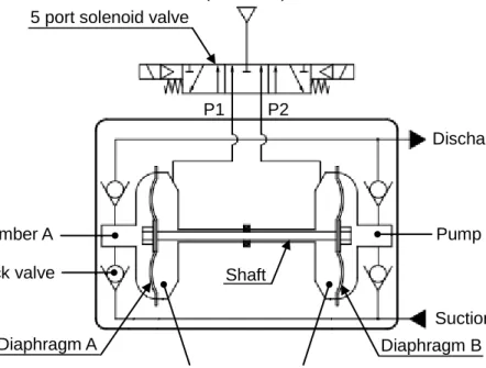
9. Construction and operating principle
First, the air is supplied for switching valve mounted outside the pump. Then the signal is given from timer etc. and the air starts flowing into each actuating chamber in turn and moves diaphragm up and down.
10. Operating principle
As shown on Fig. 1, when the air flows into actuating chamber A, the fluid is discharged away
from the pump chamber A and sucked toward the pump chamber B.
Then, the solenoid valve is switched by timer etc. and the reverse operation is performed. (Fig. 2). The pump repeats these two operations in turn and performs suction and discharge of fluid continuously. Actuating chamber A Actuating chamber B Discharge port Pump chamber B Pump chamber A Suction port Pump chamber A Diaphragm Suction port Discharge port Pump chamber B Actuating chamber A Actuating chamber B
Fluid flow Air flow
Fig. 1 Fig. 2
Air supply port (AIR SUP)
Discharge port (FLUID OUT)
Suction port (FLUID IN)
Pump chamber B
Drive chamber B
Diaphragm A Diaphragm B
P1 P2
5 port solenoid valve
Drive chamber A Check valve
Pump chamber A
13
11. Sensor mounting (leakage sensor)
Series PAF can have a sensor for detecting diaphragm breakage. If liquid leaks in the pump through the diaphragm, this sensor responded it, and detects diaphragm breakage.
<Mounting>
1. Remove the round head Philips screws below the AIR SUP port of the pump. Then, remove the leakage sensor cover, plug, and O-ring (Fig. 1). The O-ring, leakage sensor cover, and round head Philips screws are used again later. Do not throw them away.
2. Mount the O-ring again to the part from which it is removed, and insert 2 leakage sensors there. Put the leakage sensor cover back to the part with the round head Philips screws (tightening
torque: 0.125N・m) (Fig. 2).
3. Insert optical fibers to the amplifier, and set the amplifier to “Percent tuning”. At this time, the
ratio at the threshold level is set to 20~25% (※1).
Name of components
① O-ring 2pcs
② Plug 2pcs
③ Leakage sensor cover 1pcs
④ Round head Philips screw 2pcs
⑤ Leakage sensor 2pcs
Note1 This value is a reference value. Please inquire of local supplier or SMC when you cannot confirm operation even if the proportion at the threshold level is set.
Note2 Two sets of fluid-leakage sensor "KT-PAF3-47" are required for one pump.
Also, one piece of amp "HPX-EG00-1S-L02" manufactured by Azbil Corporation is required for one sensor to detect the fluid leakage (two amps are required in total).
Note2)
Caution
Tighten two ④round head Philips screws with torque
0.125N
・
m
. ① ③ FLUID OUT FLUID IN P1, P2 ② ④ ⑤ ① ③ ④14
Revision
18-Aug-2020 Revision D
- Completely revised by format change.
- Change the part number of amp for the sensor. - Delete Sensor mounting (stroke sensor).
4-14-1, Sotokanda, Chiyoda-ku, Tokyo 101-0021 JAPAN Tel: + 81 3 5207 8249 Fax: +81 3 5298 5362
URL https://www.smcworld.com
Note: Specifications are subject to change without prior notice and any obligation on the part of the manufacturer.