Obstacle Sensing Autonomous Mobile (OSAMO) Robot By
Effidz Syufrie bin Muhd. Shukor
Dissertation Report submitted in partial fulfillment of the requirements for the
Bachelor of Engineering (Hons) (Electrical & Electronics Engineering)
CERTIFICATION OF APPROVAL
OBSTACLE SENSING AUTONOMOUS MOBILE (OSAMO) ROBOT
By
Eflidz Syufrie bin Muhd. Shukor
A project dissertation submitted to the Electrical & Electronics Engineering Programme
Universiti Teknologi PETRONAS in partial fulfillment of the requirement for the
BACHELOR OF ENGINEERING (Hons) (ELECTRICAL & ELECTRONICS ENGINEERING)
Approved by:
Dr. Noohul Basheer Zain Ali Project Supervisor
UNIVERSITI TEKNOLOGI PETRONAS TRONOH, PERAK
CERTIFICATION
OF ORIGINALITY
This is to certify that I am responsible for the work submitted in this project, that the original work is my own except as specified in the references and acknowledgements, and that the original work contained herein have not been undertaken or done by unspecified sources or persons.
ABSTRACT
The objective of this project is to design and produce an Obstacle Sensing Autonomous Mobile (OSAMO) Robot that can be use in the industrial or for domestic purpose. Robots may be used to perform tasks that are too dangerous or difficult for human, such as radioactive waste clean-up, or maybe perform a simple task and various daily activities domestically such as delivers some package to the
specific destination or cleaning the house. The Scope of Study will cover areas of research done to fulfil design requirements of the project with its objective and functionality. The areas of design requirements will include movement mechanism, speech and voice recognition, sensors, controller and programming. Consultation with supervisors and other FYP students had aid the author in completing the project.
ACKNOWLEDGEMENTS
First and foremost the author would like to take this opportunity to express her appreciation to all the parties that is involved in making Final Year Project (FYP) a success. The undergoing of this project would have not been possible without the assistance and guidance of certain individuals and organization whose contributions have helped in its completion.
The author would like to express his deepest appreciation to his project supervisor, Dr. Noohul Basheer Zain Ali for his endless support, guidance and consultation regarding this project throughout the year.
Special thanks to lab technologist; Mdm. Siti Hawa who has given countless technical support to the author in providing both advice and components, hardware, or software the author requires in completion of the project.
Last but not least, the author would like to give out her thanks to all those who have contributed directly or indirectly to the success of this project.
TABLE OF CONTENTS CERTIFICATION OF APPROVAL ... ii CERTIFICATION OF ORIGINALITY ... iii ABSTRACTT ... iv ACKNOWLEDGEMENT ... v LIST OF FIGURES ... ix LIST OF TABLES ... xi CHAPTER l: INTRODUCTION 1.1 Background of Study ... 1 1.2 Problem Statement ... 2 1.3 Objective ... 3
1.3.1 To design a simple movement mechanism for the robot... 3 1.3.2 To he able to avoid obstacle collision ... 4 1.4 Scope of Study
... 4 1.4.1 Controllers and Programming ... 4 1.4.2 Electrical Circuits and Sensor ... 4 1.4.3 Robotic Movement Mechanism
... 5
CHAPTER 2: LITERATURE REVIEW
2.1 History ... 6 2.2 Overview ... 7 2.3 Types of Robots ... 8 2.3.1 Manipulator/Industrial Robots ... 8 2.3.2 Mobile Robots ... I1
2.4 Building Blocks of the Robots ... 13
2.4.1 Controllers ... 14
2.4.2 Sensors and Transducers ... 14
2.4.3 Analyzers ... 15 2.4.4 Actuators ... 15 2.4.5 Drivers ... 15 2.5 Controllers ... 16
2.5.1 Programmable Logic Controller (PLC) ... 16
2.5.2 Programmable Input Controller (PIC') ... 16
2.6 Electronics Circuits ... 18
2.6.1 Collision Avoidance and Detection ... 18
2.6.1.1 Infrared Sensor ... 18
2.7 Mechanical Drives ... 23
2.7.1 Choosing the Right Motor for the Job ... 23
2.7.2 Robot locomotion with DC Motors ... 24
CHAPTER 3: METHODOLOGY 3.1 Procedure Identified ... 3.2 Tools and Equipments Required ... 26
3.3 Project Works ... 27
3.3.1 Intensive Literature Reviews ... 27
3.3.2 Mechanical and Electrical Design Drawings ... 28
3.3.3 Structure Fabrication for Mobile Robot ... 28
3.3.4 Troubleshooting and Testing ... 28
CHAPTER 4: RESULT AND DISCUSSION 4.1 The Overall Design ... 29
4.3 Microcontroller ... 32 4.4 Line Tracking ... 34 4.4.1 Infrared Sensor ... 34 4.5 Power Regulation ... 36 4.5.1 Regulate at a set voltage ... 36 4.5.2 Supply a minimum required amount of power ... 36 4.6 Collision Avoidance and Detection
... 37 4.5.1 Ultrasonic Receiver ... 37 4.5.2 Ultrasonic Transmitter ... 38 4.7 Source Code ... 40 4.7.1 Choosing a mode ... 40 4.7.2 Obstacle Following Mode
... 42 4.7.3 Obstacle Sensing Mode
... 43
CHAPTER 5: CONCLUSION AND RECOMMENDATION
5.1 Conclusion ... 44 5.2 Recommendation ... 45 REFERENCES ... 46 APPENDICES ... 47
Appendix A GANTT CHART OF PROJECT FLOW
Appendix B PROGRAM SOURCE CODE
Appendix B PIC 16F87X DATASHEET
Appendix C L78XX VOLTAGE REGULATOR DATASHEET Appendix D L298N H-BRIDGE DRIVER DATASHEET
LIST OF FIGURES
Figure 1: Diagram of spherical robot ... 9
Figure 2: Diagram of articulated robot ... 9
Figure 3: Diagram of cylindrical robot ... 10
Figure 4: Building block components of robot and automation ... 13
Figure 5: PIC 16F87X controller ... 14
Figure 6: Example of sensors and transducers ... 14
Figure 7: Example of actuators ... Figure 8: Using Infrared to Detect Obstacle ... 18
Figure 9: Circuit Diagram for Infrared Light Transmitter/Sender ... 19
Figure 10: Circuit Diagram for Infrared Light Receiver ... 20
Figure 11: Schematic of 40 kHz ultrasonic transmitter ... 21
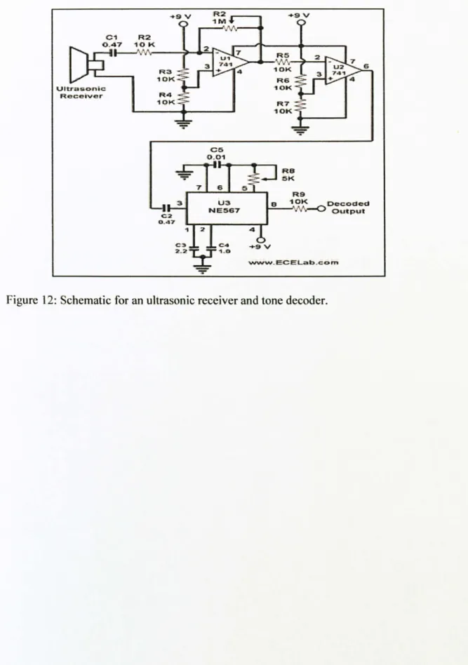
Figure 12: Schematic for an ultrasonic receiver and tone decoder ... 22
Figure 13: Direction of mobile robot with differential drive locomotion ... 24
Figure 14: Flow Chart of Project ... 25
Figure 15: Overview of the robot circuitries with the microcontroller ... 29
Figure 16: Design of the robot from the upper view ... 31
Figure 17: The box to place the microcontroller board ... 31
Figure 18: Design of the robot from the downside view ... 31
Figure 19: PIC 16F877 layout ... 32
Figure 20: Warp 13 programmer board ... 33
Figure 21: Line tracking using Infrared Light ... 34
Figure 22: Line tracking circuitry ... 35
Figure 23: Power regulation schematic ... 36
Figure 24: Schematic Diagram for ultrasonic receiver ... 37
Figure 28: Source code for Mode Selecting ... 40
Figure 29: Mode selecting mechanism flow chart ... 41
Figure 30: Source code for Object Following Mode ... 42
LIST OF TABLES
Table 1: Comparison between PIC Controller and PLC Controller ... 17 Table 2: Tools and Equipments Required ... 26
CHAPTER I
INTRODUCTION
1.1 Background of Study
A robot can be defined as an electro-mechanical machine that can be programmed to perform some specific tasks autonomously. [11 A robot doesn't need to possess intelligence, but does need a basic set of instructions that enable it to function in the environment it is placed in. Robots may be used to perform tasks that are too dangerous or difficult for human, such as radioactive waste clean-up, or maybe perform a simple task and various daily activities domestically such as delivers some package to the specific destination or cleaning the house. Robots also can be used to perform repetitive works that needed high precision and high focus as human tends to become careless and tired if works in a long time.
Robots today are being utilized in a wide variety of industrial applications. Any job that involves repetitiveness, accuracy, endurance, speed, and reliability can be done much better by robots, which is why many industrial jobs that used to be done by humans are increasingly being done by robots. For example, for the past 30 years or thereabouts robots have progressively taken over the fully automated production lines of the automobile industry, wherein a chassis of a vehicle is transported along a conveyor belt and is welded, affixed, painted, and assembled by a succession of robot stations. [2]
1.2 Problem Statement
On a daily basis, there are many activities needed to be done by human from a simple task of delivering package to its drop off locations; i. e. to deliver mails to the neighbors, or maybe a dangerous or difficult task to be completed in the volcano, and sometimes human just do not have the time to do it all. Either domestic or industrial use, the robot is the perfect candidate to replace human to perform this entire task thus can reduce the human labor. As the robot will work directly with human, a simple speech system will make the robot appears friendlier and funnier to the users.
However, the cost to build a robot is a major concern especially for domestic or small scale purpose. The success of designing an inexpensive autonomous robot would attract users domestically.
This has given the author an idea to design an inexpensive, autonomous robot for domestic use. The robot should be able to turn and move around, sensing obstacle, and also greet people in friendly manner.
1.3 Objective
The objective of this project is to design and construct a robot which would be able to turn and move around, able to avoid collision of obstacles along its pathway and also will greet people in a friendly manner. The robot also can be use to deliver packages to assign person or maybe to be a messenger to deliver a simple message to the assign person. Cost will be minimized to achieve minimal expenses throughout project.
On the first semester of the FYP, the author will make a lot of research in literature review in designing a wholly functioning robot meets the required criteria, and on the second semester, the author will build the actual design and construction while modifications will be done along the way to improve the initial design. Programming and integrating systems will be done after the author has finished designing the whole robot.
There are a few objectives need to be achieved by the end of project completion.
1.3.1 To design a simple movement mechanism for the robot.
The design of the movement mechanism for the robot must be simple yet effective. This is to make sure that the objective can be achieved in the given period. A simple mechanism also can reduce the complexity of the programming of the robot and reduce cost.
1.3.2 To he able to avoid obstacle collision.
The robot moves by itself and will not be controlled by the human. So, the robot must be able to avoid obstacle collision along its pathway. Fail to do so will cause the damage to the robot and also failure to move due to the obstacle blocking its way thus the objective of the robot unmet.
1.4 Scope of Study
The scope of study can be divided into four subsections. In which interdependency and coordination between all four subsections must be developed to produce a functioning mobile robot.
1.4.1 Controllers and Programming.
Controllers can be assumed as the brain of the robots. The author will directly save the programming and all the instruction to the memory in the controller. The controllers will control the robot as per the programming and instructions that has been set by the author. The author will use PIC microcontroller rather than PLC microcontroller because the former is cheaper than the latter. The programming language required for this controller is C programming.
1.4.2 Electrical Circuits and Sensors
Suitable sensors are needed for collision avoidance system. Electrical circuits are needed to supply regulated and stable power for the robot. The electrical circuit for the speech system is also needed to be done maybe by using speaker or buzzer.
1.4.3 Robotic Movement Mechanism
The movement mechanism will be provided by using proper motors and actuators. The motors and actuators are the "muscles" of the robot. A specific design of motors and actuators are needed to produce the desired output and tasks.
CHAPTER 2
LITERATURE
REVIEW
2.1 History
The first recorded design of a humanoid robot was done by Leonardo Da Vinci (1945). Da Vinci's notebooks, rediscovered in the 1950s, contain detailed drawings of a mechanical knight now known as Leonardo's robot, able to sit up, wave its arms and move its head and jaw. [3]
The first known functioning robot was created in 1783 by Jacques de Vaucanson, who made an android that played the flute.
Nowadays, there are many robots that can do different tasks. The most recognizable is ASIMO (Advanced Step in Innovative Mobility) created by Honda, which is a humanoid robot that can walk, run and also can interact with human.
2.2 Overview
A robot is defined as an electro-mechanical machine that can be programmed to perform some specific tasks autonomously. A robot doesn't need to possess
intelligence, but does need a basic set of instructions that enable it to function in the environment it is placed in. Robot can be use in the industrial or for commercial purpose.
Robots are used to perform tasks that are too dangerous or difficult for human, such as radioactive waste clean-up, or maybe perform a simple task and various daily activities domestically such as delivers some package to the specific destination or cleaning the house.
Robotic technology has improved vastly from a robot that can only do simple task to a robot that can operate the whole factory. Many factory jobs are now performed by robots. This has led to cheaper mass-produced goods, including automobiles and electronics industry which needed high precision workmanship.
2.3 Types of Robots
Generally, the types of robots can be divided into two categories in which:
I. Manipulator/industrial robot: Robot stationed in one location and able to move other objects such as the robotic arm for material sorting process.
2. Mobile robot: Robots which are able to move about.
2.3.1 Manipulator/Industrial Robots
A robot that is stationed in one location and able to move other objects such as the robotic arm for material sorting process for example factory automation with industrial robots for palletizing food products like bread and toast. These robots are able to perform quality of work due to fatigue or weariness and they are able to operate for long hours. Some examples of industrial robots used in the market
include:
a) SCARA robot
Commonly used in assembly applications, this selectively compliant arm for robotic assembly is primarily cylindrical in design. It features two parallel joints that provide compliance in one selected plane. The name SCARA means Selective Compliance Assembly Robot Arm which was introduces in the late 1970 as a robot ideally suited for assembly task. One of the main reasons this robot excels is because of the compliance feature it offers. "Compliance" is a robotic term that means that the robot is capable of adjusting to accommodate misalignment. [4]
b) Spherical robot
It is able to handle machine tools, spot welding, die-casting, gas welding and arc welding. It is a robot whose axes form a polar coordinate system and create a
spherical-shaped work envelope. [4]
Figure 1: Diagram of spherical robot
c) Articulated robot
A robot which resembles a robotic arm, used for assembly operations, die- casting, fettling machines, gas welding, arc welding, and spray painting. It is a robot whose arm has at least three rotary joint. Each joint is called an axis and provides an additional degree of freedom, or range of motion. Industrial robots commonly have
tour or six axes. 141
d) Cylindrical robot
Normally used for assembly operations, handling at machine tools, spot welding and handling at die-casting machines. It is a robot whose axes form a cylindrical coordinate system. Cylindrical robots operate within a cylindrical-shaped work envelope. [4]
rcýM
i
ý. Ti
2.3.2 Mobile Robots
Also known as Automated Guided Vehicles, or AGVs, these are used for transporting material over large sized places like hospitals, container ports, and warehouses, using wires or markers placed in the floor, or lasers, or vision, to sense the environment they operate in, These robots have the ability of performing tasks that are non-sequential and non-repetitive in environments that are complex. [2] Such ability allows the robots to be used in various fields such as:
a) Underwater exploration
Robotic underwater rovers are used to explore and gather information about many facets of our marine environment. Project Jeremy, is collaboration between NASA and Santa Clara University. An underwater telepresence remotely operated vehicle (TROV) was sent by scientist into the freezing Arctic Ocean waters to investigate the remains of a whaling fleet list in 1871. The TROV was cable operated, which carried power and instructions down to the robot and the robot returned video images. The TROV can also collect artifacts and gather information about the water conditions. [l]
b) Duct Cleaning
In the hazardous and tight spaces of a building's duct work, many hours can he spent cleaning relatively small areas if a manual brush is used. Robots have been
used by many duct cleaners primarily in the industrial and institutional cleaning markets, as they allow the job to he done faster, without exposing workers to the harmful enzymes released by dust mites. For cleaning high-security institutions such as embassies and prisons, duct cleaning robots are vital, as they allow the job to be completed without compromising the security of the institution. Hospitals and other government buildings with hazardous and cancerogenic environments such as nuclear reactors legally must be cleaned using duct cleaning robots, in countries such as Canada, in an effort to improve workplace safety in duct cleaning. [I]
2.4 Building Blocks of the Robots
Robots and automation is made up of various building blocks, in which are interdependent to each other for the successful implementation and function of the robot. Failure in one of these blocks will affect the overall process of the automation. The building blocks of a robot consist of
1. Controllers
2. Sensors and Transducers 3. Analyzers
4. Actuators 5. Drivers
External Device (Timer and Circuits)
Actuator
a
V
Analyzer (DAC) Vv
Controller (PLC/PIC) SensorsE:
*
Figure 4: Building block components of robot and automation.
2.4.1 Controllers
Controllers can be assumed as the brain of the robots. The author will directly store the programming and all the instruction to the memory in the controller. The controllers will control the robot as per the programming and instructions that has been set by the author.
The author will use PIC 16F87X microcontroller rather than PLC microcontroller because the former is cheaper than the latter. The data and the information will be inputted to the controllers, processed according to the program defined and executed via the outputs. The programming language required for this controller is C programming.
-, 1 o
Figure 5: PIC 16F87X controller 2.4.2 Sensors and Transducers
Sensors are the devices that generated output signal for the purpose of sensing a physical phenomenon. Manual switch will be used as the on-off switch for the robots. Another type of sensors is those that do not require physical contact. These proximity sensors are capable of sensing the presence of nearby objects without touching it; i. e. infrared sensors, photoelectric sensors and the ultrasonic sensors.
2.4.3 Analyzers
The function of the analyzers is to register and analyze the output signals produced by the sensors or devices. It will convert the input signal from analogue to digital by using ADC (analogue to digital converter) that can be understand by the robots.
2.4.4 Actuators
After the signal is sensed and analyzed, actuators will perform direct physical action for a particular process. Actuators may include solenoid and cylinders.
Cylinders usually for pneumatic types and may be used in robots that grips. [5]
Figure 7: Example of actuators
2.4.5 Drives
Like actuators, drives take some action from the process command from the controller or to other analyzer. The difference is that actuators are used to affect a short, complete, discrete motion (usually linear) and drives executes more continuous movements typically motors. [5]
2.5 Controllers
Controller can be assumes as the brain for the robot. In order to build an effective but inexpensive robot, a suitable controller needed to be used. Below are the comparisons between the two microcontrollers that might be used in the author project.
2.5.1 Programmahle Logic Controller (PLC)
The PLC is a digitally operating electronic apparatus which uses a programmable memory for the internal storage of instructions by implementing specific functions such as logic sequencing, timing, counting, and arithmetic to control, through digital or analogue input/output modules. [6]
2.5.2 Programmable Input Controller (PIC)
The PIC microchips are used for embedded designs. The Microcontroller is able to perform various functions according to the user programming codes (Assembly Language/C Programming). The microcontroller is able to perform task which is once difficult to be implemented on normal logic circuit.
Table 1: Comparison between PLC and PIC controllers.
CRITERIA PLC PIC
Control Device (Hardware)
General purpose Specific purpose but programmable
Control Scale Medium and large Small scale is likely to succeed Change or Addition of
Specification
Easy Moderate (depends on the
programming skills of the user) Delivery Period Almost immediate Almost immediate
Maintenance Easy Moderate
Reliability Very high Not able to withstand industrial
environment
---- -
Economic Efficiency Advantage on large scale operation
--- --- - Cheap
2.6 Electronic Circuits
2.6.1 Collision Avoidance and Detection
There are two different types of detection system. One is passive detection system, where the robot only changes direction after the collision happens. To make sure that the robot can avoid the obstacle, an active detection system must be used. The system would detect an obstacle from a defined distance while depending on the sensitivity of the sensors), and changes course of direction before collision.
2.6.1.1 Infrared Sensor
Light may always travel in a straight line but it bounces off nearly everything. This is advantageous to build an infrared collision detection system. The circuit below in Figure 8 is an example on how the infrared LED can be used for the purpose of detecting obstacle like a wall or an object in its path.
IR LI1: DSý
1D
- m ý
! 11\II I1 1) II:
a) Infrared Transmiller
The transmitter LED is composed of an infrared LED (D2) in series with a 470 Ohm resistor, yielding a forward current of 7.5 mA. For this design, the light transmitting range can be varied from 1 to 10 cm depending on the ambient light in the environment. The resistor provides means to increase or decrease the range of the light transmission. [7]
h) lnfrured Receiver
For the receiver part, the 2 resistor R5 and R6 forms a voltage divider which provides 2.5V at the anode of the infrared LED. When the LED (DI), receive the light from the reflection, the voltage drop increases, the cathode's voltage of DI may go as low 1.4V depending on the light intensity. The voltage drop is detected by the OP-AMP. The variable resistor, R8 is adjusted so that the voltage at the positive input of the OP-AMP would be somewhere near 1.6V. So, when D1 receive the light, the
voltage drop at the cathode of Dl become lower than 1.6V and the output becomes high. [71
h) Ultrasonic Sensor
Sound can be used to detect the proximity of objects in much the same as for infrared light. Ultrasonic sound is transmitted from a transducer, is reflected by a nearby object, and then received by another transducer. The advantage of using sound is that it is not sensitive to objects of different color and light reflective properties, However, there are some materials that reflect sound better than others, and some even absorb sound completely. In comparison, proximity detection with sound is
more fool proof.
The circuit below provides a practical circuit for building ultrasonic proximity detector. A stream of 40 kHz pulsed is produced by a 555 timer wired up as an
astable multivibrator. The output of the 555 provides more than enough power for the transducer. A piece of foam between the transducers is needed to eliminate direct interference between the two. [8]
ý+12V R1 IOK R2 1K C2 O. 1 Cl 0.0033
BL
VDD 555 OUT GNOI
R4 2.2 K 2N2222 3 R3 1.2 K www_ECELab. com Ultrasonic Transducer2.7 Mechanical Drives
2.7.1 Choosing the Right Motor f or the Job
Motors are the muscle of the robot; whether to move other objects or to move the robot itself. There are several types of motor normally used by robots, which are the stepper motors, DC continuous motors and the servo motors.
DC Motor: The most common motor normally used to drive continuously in one direction. It only stops when the power supply is removed.
Stepper Motor: Application of power causes the shaft to rotate a few degrees and then stop. Continuous rotation of the shaft requires the power to be pulsed to the motor.
Servo Motor: Strong motors normally used as joints for robots. It can only move 180 degrees in direction.
2.7.2 Robot Locomotion with DC Motors
Most robot designs use two identical motor to spin two wheels. These wheels provide forward and backward momentum, as well as left and right steering. Stopping one motor, would allow the robot to change direction. Reversing both motors in relative to one another, robot turns by spinning on its wheel axis. This would cause sharp right and left turns. [91
Forward Reverse I ý Rightturn I
molloot-i
Left turn I sommmon--i4
ýHard right turn Hard left turn
CHAPTER 3
3.1 Procedure Identification
Below in Figure 14 is a flow chart describing the project methodology step- by-step in more detail, including intensive literature reviews, the mechanical and electrical design drawings and the structure fabrication for mobile robot.
METHODOLOGY
Intensive Literature Reviews and Research T Robot Mechanism and Control T PIC Programming v
Figure 14: Flow chart of project
Mechanical and Electrical Design Drawing
Structure Fabrication for Mobile Robot Troubleshooting, Testing and Improvements Sensors and Coordination Final Product
3.2 Tools and Equipments Required
Below in Table I are the expected tools and equipments needed for completion of the autonomous robot. These tools are obtainable for use from UTP Hardware Store and UTP Mechanical Engineering Laboratory and the software needed can be downloaded from the internet for free.
Table 2: Tools and Equipments Required
No Parts Materials Tools
I. Structure 1. Metal 1. Drill
2. Welding
2. Movement 1. DC motor with gears(2) I. Screw drivers
2. Casters(2) 2. Pliers
3. Nuts and Screws 4. Plastic wheel coupled(2)
3. Power 1. Batteries(I 2V) 1. Solder & flux
distribution 2. Connectors & Wires 2. Multimeter
3. Ribbon Cable 3. Screw drivers
4. Sensors 1. Infrared LEDs 1. PSpice
2. Ultrasonic Sensor 2. Breadboard
3. Electronic Components 3. Solder & flux 4. Multimeter 5. Oscilloscope
5. Microprocessor 1. PIC Controller 16F87X 1. Breadboard 2. PIC Programmer Board 2. Electronics 3. PIC 16F87X Target Board components
3. Oscilloscope 4. Programming
3.3 Project Works
3.3.1 Intensive Literature Reviews
Intensive literature reviews has been done on mobile robot fabrication. There are seven references that the author used for gaining knowledge on how to build a mobile robot. Resources from related books, internet and online journals have been accessed. The reviews are crucial to identify the method, tools and equipments that are needed for implementation of the robot. The literature reviews cover four
important areas which are:
a) Robot Mechanism and Control
Mechanical trajectory and dynamics calculation needed to be done to identify the type of locomotion to be used, the torque of the motor needed and mechanisms that would be implemented to the design.
b) Sensors and Coordination
Identify the best suited sensor for the obstacle avoidance of the robot which is the active detection system.
c) PIC Programming Language
Learning the programming language (C++) which will be used to program the microcontroller selected for this robot which is the PIC chip.
3.3.2 Mechanical and Electrical Designs Drawings
The mechanical structures are drawn out by using specific software such as AutoCAD which includes the details in which the real robot would resemble. The electrical design will be done by using Multisim Electronic Workbench software for simulation purpose to test the theory and check the sufficiency of voltage and current supplied to the circuitry.
3.3.3 Structure Fabrication for Mobile Robot
The fabrication of this robot will be the final step after all the research has been done thoroughly. The body of the robot will be constructed and all the major components of the robot will be combines. After the fabrication completed, various tests will be done to make sure that the robot will function perfectly.
3.3.4 Troubleshooting and Testing
Troubleshooting is needed to ensure a functioning robot is produced at the end of the project period.
CHAPTER 4
RESULT AND DISCUSSION
4.1 The Overall Design
RCL OO 5V 4.0MHz Left Motor
Line Tracking via Infrareds
AO Al A2 Microcontroller 16F877 VDD DO CLKIN Dl C4 C6 C5 C7 H-bridge I79RN LLý- Right Motor
Figure 15: Overview of the robot circuitries with the microcontroller.
Ultrasonic Sensors Other Circuitry
4. I. 1 Component Functions and Interaction
With the reference to the Block Diagram shown in Figure 9, the functions of the components are described below:
a) PIC 16F877 Microcontroller
The overall process of the robot is determined by this chip. The chip receives inputs from the sensors and processes it to execute appropriate instructions according to the program written by the programmer. The controller also controls the drives such as the DC motor according to the path planning codes written.
b) DC Motors
The DC motors are used to move the robot about. The motor has sufficient
amount of torque in order to successfully move the whole structure.
c) Line Tracker
The line tracker is essential for movement from point to point of the robot. The line tracker is design to follow white lines over work area to get around.
d) Ultrasonic Receiver/ Transmitter
The ultrasonic sensor is essential for the obstacle avoidance feature in this robot. When an obstacle is detected along the predetermined path of the robot, a signal would be sent to the microcontroller by the ultrasonic sensors. The obstacle avoidance program would then be executed to avoid any collision of the robot.
4.2 Structure and Design
The author has designed the robot to make sure that it meets the required criteria. On the front of the robot, there are Ultrasonic sensors (transmitter and receiver) to detect the obstacle. There is also a box on the robot to place the microcontroller board.
Figure 16: Design of the robot from the top view
Figure 17: The box to place the microcontroller board
4.3 Microcontroller
The author had decided to make use of the 16F877 by the manufacturer Microchip. Please find attached in Appendix the datasheet for the microcontroller. The PIC 16F877 shown in Figure 19, features 256 x8 bytes of EEPROM data memory, self programming, an 1CD, 5 channels of 10-bit Analog-to-Digital (A/D) converter, 2 additional timers, 2 capture/compare/PWM functions, the synchronous serial port can be configured as either 3-wire Serial Peripheral Interface (SPIT"') or the 2-wire Inter-integrated Circuit (IZCTM) bus and a Universal Asynchronous Receiver Transmitter (USART).
40-Pin P DIP b1ýLR'' "=p -ý ? ^L: AN0 ý-+ ? A3'AWý''lae't ýw ?'`: AýI4''J. `'s'l. ýr ti I "--" ? Eý: Fý. 'ýJO ý--« V» : `ý sý CSCVvL, - GSvZ'CLP: 0 -S0"T'ý150'T'Cý . ýý =C1: TIGSI:, ^. CPý . --r RC2: Z'-CP1 ý--. P. C? 'SvP: SCL +-+ RCC =3P0 ---ý RC1: =SP1 t1 iý 14 J° *1 ý -, - ý- , - ,G Z4 P. U: PGD
Figure 19: PIC 16F877 layout.
P. 6tv PG" P. 65 +-- P64 ., -. P6SýPG', 1 r--. P62 ý--ý R6? -ýý PKN- -º P. C?: =3P6 RC;: =3P5 ý. RCt: vP4 RC?: PJ; CT . -ý RCa-TXICK. P. C! ''_-'DC . -"- RCt: Q_DI-, CA P, CT=3P3 -"-+ RC? ý=3Pý
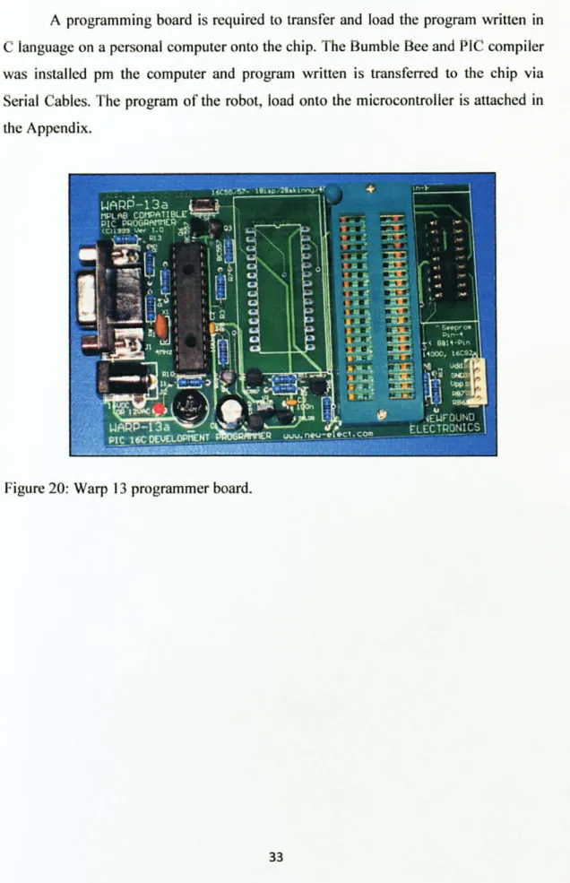
A programming board is required to transfer and load the program written in C language on a personal computer onto the chip. The Bumble Bee and PIC compiler was installed pm the computer and program written is transferred to the chip via Serial Cables. The program of the robot, load onto the microcontroller is attached in the Appendix.
Figure 20: Warp 13 programmer board.
{. r ý 1Y ýI = {rr {r Ir" {. r {P r {. r 1. C ºP0 º! or d I1P. ý R-!. ý. ýj, ý" pýý ýýrpR"ý Ifa pý ý tu_ti º+ ýý
4.4 Line Tracking
4.4.1 Infrared
. Sensor
The basic idea is to send infrared light through infrared LEDs (transmitter), which is then reflected by the embedded white lines on the floor. Then the reflected light is received by the exact same type Infrared LED (receiver).
The receiver LED produces a voltage difference across its leads when it is subjected to light. In order to detect a small voltage change, an Operational Amplifier (OP-AMP) is used. v L i7 L ý "J , ý... V. // V 1ý1
i2ý
e
V ý ý ý ü ý.. VJ , ý/ ONlf7'
1'. 'lute im reflective Black: or non-re fle.: tn-e -all face
Figure 2 I: Line tracking using Infrared Light.
The line tracking circuitry will make use of one IR emitters on each side of the white line and one in the center of the line. These IR emitters are programmed to avoid the white line hence aligning the robots movement to actually follow the white line. This line tracking will act as guidance for the robot to move on the constructed testing track. 1; _n Zý-r- R 1-r R28 ; t. -- i R29 t ý--- 4 I : U'ý ý'. ý R1ý S. 1 j ýpl' Si > ýRLS S N, }R[u Sl 1 -1: 1ý ýZ : ý2 N. 11 GSJý Rl: rsBuý LmuI ffu 11: 3, 11 ý
ýýJ
, ýý
ý-ýt
J yi ý ,ýý , 5= ýý ýý' ,: 'K'ý
;ýlJ ýý
ý
L% 1324 O[; n vý. Lý- L'ý tw Ltlw VI GND L\_+- L\. 4- 1\? L\3- O[: r. z OlT3ýi r2ý
Figure 22: Line tracking circuitry
P ý-. 9+ s t'Fa , LEDý " Sý r_rn ý r l) o ý' R_'_, w _su ý--1 660 -
However sunlight can flood the sensors to the point of being useless. Our sun emits large quantities of light in the infrared spectrum, and although the human eye is
blind to it, electronics are not. For obvious reasons the IR emitter/detector circuit is quite sensitive to even the smallest amount of sunlight. So, it is important to develop a shield that blocks the light.
4.5 Power Regulation
A power regulator circuit basically ensures control of the robots' power source. A power regulation circuit must do the following for the robot.
-l. 4.1 Regulate al a sel voltage.
For efficiency, optimally it would be best to use a power source closest (yet slightly above) the desired voltage input required. However this is rarely easy or even feasible. For a start, different electronics require different voltages. A microcontroller will require 5V, motor perhaps 12V, a voltage amplifier perhaps both 20V and -20V. Batteries are never at a constant voltage. A 6V battery will be at around 7V when fully charged, and can drop to 3 to 4V when drained.
4.4.2 Supply a minimum required amount of power.
The sum required power of all the robot components needs to be below the amount the power circuit can supply. If power drops even for a fraction of a second below what the robot requires, things like the microcontroller could reset, or sensors would give bad readings, or motors won't work very well.
Si 0 I S'1%. -,. fide D' L\t'ý'if-Saý 1N 106' 'i J V4 -11 , +c io
r
0. luF 7 Cs-0 iTa
IL:
251'. i'L' 5V<<. ýýLID_mm
R10 fy$f
4.6 Collision Avoidance System
4.6.1 Ultrasonic Receiver
The circuit has been designed based on the schematics shared on the internet by the electronic hobby kit webpage. The design circuit in Figure 24 allows the relay switch to activate when the receiver detects ultrasonic waves.
The circuit works based on the ultrasonic transducer when sensing ultrasonic signals. it converts it to electrical input with the same frequency. These signals are amplified by transistors T3 and T4. Then the amplified signals are the rectified and filtered. The filtered DC voltage is given to inverting pin of op-amp 1C2. The non inverting pin is connected to a variable DC voltage in which the threshold value of ultrasonic signal received can be manipulated. The output of op-amp is used to bias transistor T5 which will then bias the transistor T6. When transistor T6 conducts, it actuates the relay. The relay can be used to control any electrical or electronic equipment such as the controller.
4.6.2 Ultrasonic Transmitter
The ultrasonic transmitter uses a 555 based astable multivibrator. It oscillates at frequency of 40 to 50 kHz. The transmitter is powered from a 9V or 12V supply. The value of 4.7k with ±10k (pin 7) and the value of 18k (pin 6) and Cl of 680picoFarad was chosen to generate a 40 kHz to 50 kHz frequency. The 40 kHz
frequency can be calculated using the formula below.
f-
ýC-. GY. Gr r : u"ý _ýL-1
71 L '1. "1'-^ ia1- II .11 UJ -dr ft:. T 'rr; R -. - UPf=
1.44 (2R2+R1)C1 1.44 (2X18k+15k)68OpF f- 41.522 kHz[UJi r7 11i1i L. lzE I klrl
LM ý_ ý. ^_ýi: }' IC1 666 ýý+ i5
-T-c--.
2
ý C: 1`IS141Figure 25: Schematic of ultrasonic transmitter.
ý- ý .. ýx,
CSC
ý ý ý? 5 «Ga: )_" IrI: i; JT. :.: T- 1; inr Tw T_ý_F... ... ... ... ... ... v1. ... ... ... . ... ... . ... . -. .... . ... ... . ý. i . ... . ... ... ... ...: RS' - -I II F- i... ... ...::::::: --ýVV1- ... 226A ... ... . ... . ý:::: ... ... ... R1 ý .. ýý ý ... . .... I^^ ... , Jr....,:. 1... : :. '... - ... .... N'... I.. :1... ... . ... . ... . ... . ... ... H' . .. -vvr-,. ... . ... . ... p2. 1: l7kCl .... :I::: . ... .. ý.. INJ1J8 .... . ... ý .... "ý .. i.... ýý. ... ý.. ý...: nc. mon ý. ý. _.. ý... 8. .
ý ýI.. . ... ... ý_ I(-;
r:::...
.
.... ... " .. I ... I ... ... 1. ý ... t... ... .. ... ... 1*111H . ... I I.. .... ... .... BC177AP. I l1 I G2 Lfi1555CM "'G80pF " 1DnF::: 1::::::::: T : : T::::::
::::::::: ::::: :.
... ... ... . ... ... ... ... ... ... ... ... ... . ... ... ... ... ... ... ... ... ... ...Figure 26: Simulation for Ultrasonic Transmitter on Electronic Workbench.
" ý rFan p. T .. .ý RZ ... .... "ý ... . lskf) ... 0 :3...
-I::::::::
ua, ) :; ika L ý ýý., __1 r__-__. _ý . ýT J, . xsci... ýX _. --- -- --- -ý@ N991! 02 r_ . r_ --ý- Em-f- ýji:; Jr9
4.7 Source Code
The complete source code will be attached in Appendix A.
4.7.1 Choosing a mode i void main(void) unsigned char m--0, i =0; dclay(20000), 'nit'); buzzer = I; Icd_clro ,
send string("Select male`); Icd goto(20); send_string(modcjmj ); buzzer = 0; while(1) I il7 ! swl) w-hile(! swl ); m++;
I/ initiate cnfiguration and initial condition // inditcate the circuit is on with beep // clear the LCD screen
//display "select mode" move to 2nd line
display string according to the mode // stop beep
// loop
// f1' button SW I is pressed H wait until button is released if( m>2)m=0; Icd_goto(20); send _string(modcjm j); scnd_string(" "); if(! sw2)
// if mode is added more than to, set to zero // start display at 20
// display string depend on mode // space to overwrite long words // if button SW2is pressed while(! sw2); I/ wait until button is released
switch(m) If check what is the current mode, execute the mode
i
case 0: line follow(. /l mode IA ne follow break;case I: object-follow(). mode 2: object following mode break;
case 2: analog scnO; // mode 3: analog sensor mode break;
default
1
I
s
s
START INITIALIZE PIC BUTTON 1 PRESSED? YES INCREASE MODE EXECUTE CURRENT MODE % ý\. - -ý ßV TTO N3 `ýýý PRESSED?
Figure 29: Mode selecting mechanism flow chart
Based on the flowchart in Figure 29 above, the steps in choosing the mode for the robot are as below:
1. Turn on the power for the microcontroller and the PIC will be initialized. 2. Press button U switch I to increase the mode. Starting mode is Mode I. The
current mode will be displayed on the robot's LCD. Mode I: Line following
Mode 2: Object following
Mode 3: Analog Sensor/Obstacle Sensing 3. Press button 2/switch 2 to execute the mode. 4. Press button 3/switch 3 to reset the whole process.
4.7.2 Object Following Mode
void object_foltou(void)
I
int distance;Icd_ctr )
send string("Distance");
variable for distance measuring clear lcd // display string while(l) Icdgoto(20): rcad_adc(CIIANNELI ); distance = result; dis_num(result); lcd goto 2nd line
read ade channel I( analog distance sensor input) assign distance as the result oIl he reading // display the value
if (distance> 333) slop(); buzier = 0; else if(distancc> 280) backward(); SPI: FDI. = 255; SPEEDR = 255, buzzer = 0; l
//check if'distance more than 333 // stop
// check if distance more than 280 H backward with medium speed
Figure 30: Source code for Object Following Mode
In Object Following mode, the robot will actually follow a particular object so that it can maintain the distance between the robot and the object. Backward in the source code does not mean that the robot will move in a reverse motion. The analog sensor is installed on the backside of the robot thus backward in this source code is actually a forward for the robot. From the source code, the robot will maintain its distance for about 333 IR Sensor values which is equal to 14.5cm from the object. The IR Sensor value can be converted into centimeters by using the equation I below,
3027.4 1.2134
4.7.3 Obstacle Sensing f Icdgoto(20); read_adc(G{ANNIThI ); distance = result, dis_num(result), if (distance< 200) t backward( 1; SI'LLDL = 255; SPE[-'. DR = 255; burzcr - (1, I else if (distancc< 250) backward(); SPEIiDI. = 230; SI'GGDR = 230; bu7ý. cr = 0; else ill distance < 300)
1
J/ variable for distance measuring clear led
il display string
led gold 2nd Iine
read adc channel I( analog distance sensor input) assign distance as the result oft he reading // display the value
// check if distance less than 200 // backward with full specd
// check ifdistance less than 250 // backward with medium speed
// check if distance less than 300
stopO; // stop buzzer = 0. } else
c
right( ): SI'LIiUI. = 230; SPI: F. DR = 230; burl. cr = 1. void analog_xn(void) int distance; Icd_clr(; send_slri ng("Distance" ). while(l) i ý// else, distance more than 300 //right with medium speed and on burger
Figure 31: Source code for Obstacle Sensing mode.
In obstacle sensing mode, when the robot sensed an obstacle in a distance of 200 IR Value (27cm), it will still move forward with Full speed. When the distance from the obstacle becomes 250 IR Value (20.6cm), the robot speed will be decreased but still moving forward. Lastly, when the distance between the robot and the obstacle reach 300 IR Value (16.5cm), the robot will move to the right to avoid the obstacle collision.
CHAPTER 5
CONCLUSION
5.1 Conclusion
This project needs a very careful study and consistent works. There will be many obstacles that needed to be handled and overcame in completing the tasks. However with the guidance from the supervisor and other Electrical & Electronics Engineering Lecturers, it is hoped that the author can successfully completed the job according to the schedules.
In this project, an autonomous mobile robot is designed and constructed. The robot has achieved its main objectives which are being able to detect and avoid obstacles. This PIC controlled robot project will be the stepping-stone for the future UTP undergraduates to develop new and better robotics systems. Implementing knowledge gained from the class will be different from the knowledge gain from the hands-on experience. Having all the basics for developing a good robot in house will give strong future on robotics later.
5.2 Recommendations
Some of the recommendations the author plan to look into given no time constraint are as the following.
a) User Friendly Features
The author plans to add on user-friendly features to the robot, since its function to offer a helping hand to human daily activities. In order to make sure that the robot can communicate with human, a speech recognition component must be installed. A simple speech system will be installed that will make the robot can produce voices such as "excuse me", or "hello". The output devices that will be used are speaker and buzzer.
h) Neater Design
The author plans to install housing for the robot to not only protect the frame and circuitry, but also can result in a neater robot. The author also wants to give the robot a pleasant face which can make the robot become more attractive.
REFERENCES
[I] Robot, 25 August 2009, Retrieve from htip: //en. wikipedia. org/wiki/Robot.
[21 Rita Putatunda, "Types of Robots", 9 Sept 2010
Retrieve from http: //www. buzzle. com/articles/types-of-robots. htmi
[3]
Mario Taddei, 2007. "1 Robot di Leonardo Da Vinci's Robots", 1" Edition, Leonardo3[4] Robot Types, 9 Sept 2009, Retrieve from
http: //www. robots. com/faq. php? question=robot+types
[5] Electraulics Actuator and Drives, Application Notes, 2009, REXA
[6] Programmable Logic Controller, 29 Sept 2009
Retrieve from http: //en. wikipedia. org/wiki/Programmable_logic_controller
[7]
[8]
[9]
Ibrahim Kamal, "Using an IR LED as a Sensor", 5 March 2010 Retrieve from http: //www. ikalogic. com/ir_prox_sensors. php
Ultrasonic Transmitter, 29 Sept 2009, Retrieve from http: //www. ecelab. com/circuit-ultrasonic-t. htm
Angelles, Jorge 2006. "Fundamentals of Robotic Mechanical System" Canada, John Wiley & Sons, Inc.
[101 Dominique Estival, 2009 "Inlegration of Speech and Vision in a Small Mobile Robot ", University of Melbourne
[11] Gordon McComb, Myke Predko, 2006. Robot Builder's Bonanza, 3rd Edition, McGraw-Hill
[12] Bates, Martin 2004. "Introduction to Microelectronic Systems, The PIC 16F84 Microcontroller". Great Britain, Arnold.
APPENDIX A: Gantt Chart
No. Detail/Week 12 3 4 5 6 7 8 9 10 11 12 13 14 15 16 17
1 Mechanical and Electrical Design Drawing
2 Submission of Progress Report 1
' - t - 3 Structure Fabrication for Mobile Robot
4 Submission of Progress Report 2
5 Poster Exhibition (ElectrEx) EXAM
WEEK 6 Submission of Draft Report
7 Submission of Dissertation (softbound)
8 Troubleshooting and Testing
APPENDIX B
#include <pic. h>
_CONFIG ( Ox3F32 );
/*define*/
#define swl REO
#define sw2 RE1
#define motor ra RCO
#define motor_rb RC3 #define motor -la RC4 #define motor lb RC5 #define s _left RBO #define s mleft RB1 #define s_mright RB2 #define s_right RB3
#define buzzer RE2
#define rs RB7
#define a RB6
#define lcd_data PORTD
#define b_light RB5
#define SPEEDL CCPRIL
/*global variable*/
unsigned char data [4] = {0};
tonst unsigned char line [] = ("1. LINE FOLLOW");
tonst unsigned char OF[] = ("2. Object Following");
tonst unsigned char AS[] = {"3. Analog Sensor"};
tonst unsigned char *mode [3] = {&line[0], &OF[0], &AS[0]};
unsigned int result;
unsigned int To=O, T=O, TH=O;
unsigned char REC;
unsigned char i=O, raw;
unsigned int us-value (unsigned char mode);
/*function prototype*/
void init(void);
void delay(unsigned long data); void send_config(unsigned char data); void send_char(unsigned char data);
void e_pulse(void);
void lcd goto(unsigned char data); void lcd_clr(void);
void line_follow(void); void object_follow(void); void analog_sen(void);
void forward(void); void stop (void); void backward (void); void reverse (void); void Ieft(void); void right(void);
void read_adc(char config);
/*interrupt prototype*/ if (TMROIF)
{
TMROIF = 0; To +=OxlOO; } if(RBIF) { RBIF = 0;}
else TH = TMRO + To;
}
if(RCIF)
{
RCIF = 0;
if (RCREG =='R') data[i=0]= RCREG;
else if (RCREG == 100) data[i=0]= RCREG;
if ((data[0] =='R'))data [i++] = RCREG;
if (i>4) i=4;
}
} /*main function*/ void main(void){
unsigned char m=0, i =0; delay(20000); finit(); buzzer = 1; Icd_clr(); send_string("Select mode"); Icd goto(20);while(1)
{
if( ! swl){
while(! sw1); m++; if(m>2)m=0; Icd_goto(20); send_string(mode[m]); send_string(" ")-}
if (! sw2){
while(! sw2); switch(m) ( case 0: line-follow(); break; case 1: object-follow(); break; case 2: analog_sen(; break; default :/*initialize the microcontroller*/
void init()
{
// ADC configuration
ADCONI = Ob10000100;
If setup for capture pwm
RBIE = 1; // motor PWM configuration PR2 = 255; T2CON = Ob00000100; CCPICON = Ob00001100; CCP2CON = Ob00001100;
// Tris configuration (input or output)
TRISA = Ob00000011; TRISB = Ob00011111; TRISC = Ob10000000; TRISD = Ob00000000; TRISE = Ob00000011; // TMR 0 configuation TOCS = 0; PSA = 0; PS2 = 1;
TMROIE-1; TMRO=0; //setup UART SPBRG = 0x81; BRGH = 1; TXEN = 1; TX9 = 0; CREN = 1; SPEN = 1; RX9 = 0; RCIE = 1;
// enable all unmasked interrupt
GIE=1; PEIE = 1; // LCD configuration send_config(Ob00000001); send_config(Ob00000010); send_config(Ob00000110); send_config(Ob00001100); send_config(ObOO111000);
stop();
b_light = 0;
buzzer = 0;
stop();
}
/*mode 1: line follow*/
void line_follow(}
{
unsigned char memory; Icd_clr(); send_string(" Position"); while(1)
{
if ((s_left==1)&&(s_mleft==0)&&(s_mright==0)&&(s_right==0)){
forward(); SPEEDL = 0; SPEEDR = 255; memory = PORTB&Ob00001111; Icd_goto(20); send_string ("right ");}
else if ((s_left==1)&&(s_mleft==1)&&(s_mright==0)&&(s_right==0)){
forward(); SPEEDL = 180; SPEEDR = 255;} else if ((s_Ieft==0)&&(s_mleft==1)&&(s_mright==0)&&(s_right==0))
{
}
forward(); SPEEDL = 200; SPEEDR = 255; memory= PORTB&Ob00001111; Icdgoto(20); send_string ("m_rightl "); else if ((s_left==1)&&(s_mleft==1)&&(s_mright==1)&&(s_right==0)){
I
forward(); SPEEDL = 200; SPEEDR = 255; memory = PORTB&Ob00001111; Icd_goto(20); send_string ("m_rightl "); else if ((s_left==O)&&(s_mleft==1)&&(s_mrigiit==1)&&(s_right==O)){
}
forward(); SPEEDL = 255; SPEEDR = 255; memory= PORTB&Ob00001111; Icd_goto(20); send_string ("middle "); else if ((s_Ieft==0)&&(s_mleft==0)&&(s_mright==1)&&(s_right==0)){
forward(); SPEEDL = 255;else if ((s_left==0)&&(s_mleft==1)&&(s_mright==1)&&(s_right==1))
{
}
forward(); SPEEDL = 255; SPEEDR = 200; memory = PORTB&Ob00001111; Icd_goto(20); send_string ("m_Ieftl "); else if ((s_left==0)&&(s_mleft==0)&&(s_mright==1)&&(s_right==1)){
}
forward(); SPEEDL = 255; SPEEDR = 180; memory = PORTB&Ob00001111; Icd_goto(20); send_string ("m_Ieft2 "); else if ((s_Ieft==0)&&(s_mleft==0)&&(s_mright==0)&&(s_right==1)){
}
forward(); SPEEDL = 255; SPEEDR = 0; memory = PORTB&Ob00001111; Icd_goto(20); send_string ("left "); else if ((s_left==O)&&(s_mleft==0)&&(s_mright==O)&&(s_right==0)) { forward();if ((memory == Ob00000001) (memory
Ob00000011) ýý (memory == Ob0000O10) ýý (memory== Ob0000111))
{
else if ((memory == Ob00001000) II (memory ==
Ob0000100) II (memory == Ob00001100) 11 (memory == Ob0001110))
f SPEEDL = 255; SPEEDR = 0; 1
}
else if ((s_left==1)&&(s_mleft==1)&&(s_mright==1)&&(s_right==1)) { forward(}; }}
}/*mode 2: object following*/
void object_follow(void)
{
int distance; Icd_clr(); send_string("Distance"); while(l){
Icd_goto(20); read_adc(CHANNEL1); distance = result; dis_num(result);else if (distance> 280)
{
backward(); SPEEDL = 255; SPEEDR = 255; buzzer = 0;}
}
)/*mode 3: analog sensor*/
void analog_sen(void)
{
int distance; Icd_clr(); send_string("Distance"); while(1){
Icd_goto(20); read_adc(CHANNELi); distance = result; dis_num(result); if (distance< 200){
backward(); SPEEDL = 255;)
else if (distance< 250)(
backward(); SPEEDL = 230; SPEEDR = 230; buzzer = 0; )else if( distance < 300) { stop(); buzzer = 0;
}
else{
right(); SPEEDL = 230; SPEEDR = 230; buzzer = 1;}
}
)
/*read adc*/
void read_adc(char config)
{
unsigned short i;
unsigned long result_temp=O; ADCONO = config; delay(10000); for(i=200; 1>0; i-=1)
t
ADGO = 1; while(ADGO==1); result=ADRESH; result=result«8; result=result I ADRESL; result_temp+=result; } result = result-temp/200; ADON = 0;}
/*motor control functions*/ void forward ()
{
motor_ra = 0; motor_rb = 1; motor_la = 0; motor_rb = 1;}
void backward ()(
motor_ra = 1; motor rb = 0; motor la = 1; motor Ib = 0;}
void Ieft(){
motor ja = 1; motor-lb = 0; motor_ra = 0;void right()
{
motor_Ia = 0; motor_Ib = 1; motor_ra = 1; motor_rb = 0;}
void stop(){
m otor_la = 1; motor_lb = 1; motor_ra = 1; motor_rb = 1;}
/*LCD functions*/void delay(unsigned long data)
{
for( ; data>O; data-=1); }
void send_config(unsigned char data) {
rs=0;
e_pulse(}; }
void send_char(unsigned char data) { rs=1; Icd_data=data; delay(400); e_pulse(; ) void e_pulse(void) { e=1; delay(300); e=0; delay(300);
}
void Icd. goto(unsigned char data)
{
if(data<16) { send_config(0x80+data);}
else}
}
void Icd_clr(void){
send_config(OxOl); delay(350); )void send_string(const char *s) {
while (s && *s)send_char (*s++); }
void dis_num(unsigned long data) (
unsigned char hundred_thousand;
unsigned char ten_thousand;
unsigned char thousand;
unsigned char hundred;
unsigned char tenth;
hundred thousand = data/100000; data = data % 100000;
ten thousand = data/10000; data = data % 10000; thousand = data / 1000; data = data % 1000;
hundred = data / 100; data = data % 100;
data = data % 10; send_char(hundred_thousand + 0x30); send_char(tcn_thousand + 0x30); send_char(thousand + 0x30); send_char(hundred + 0x30); send_char(tenth + 0x30); send_char(data + 0x30);
}
APYF. NI)IX C PIC16F87X DATASHEET
OZ
MICROCHIP
PICI 6F87X
28/40-Pin 8-Bit CMOS FLASH Microcontrollers
Devices Included in this Data Sheet:
" PIC16F873 " PIC16F876 " PIC16F874 " PIC16F877
Microcontroller Core Features:
" High performance RISC CPU
" Only 35 single word instructions to learn All single cycle instructions except for program branches which are two cycle
" Operating speed: DC - 20 MHz clock input DC - 200 ns instruction cycle " Up to 8K x 14 words of FLASH Program Memory,
Up to 368 x8 bytes of Data Memory (RAM) Up to 256 x8 bytes of EEPROM Data Memory " Pinout compatible to the PIC16C73B/74B776/77 " Interrupt capability (up to 14 sources)
" Eight level deep hardware stack
" Direct, indirect and relative addressing modes " Power-on Reset (POR)
" Power-up Timer (PWRT) and Oscillator Start-up Timer (OST)
" Watchdog Timer (WDT) with its own on-chip RC oscillator for reliable operation
" Programmable code protection " Power saving SLEEP mode " Selectable oscillator options
" Low power, high speed CMOS FLASH/EEPROM technology
" Fully static design
" In-Circuit Serial ProgrammingT" (ICSP) via two pins
" Single 5V In-Circuit Serial Programming capability " In-Circuit Debugging via two pins
" Processor read/write access to program memory " Wide operating voltage range: 2.0V to 5.5V
" High Sink/Source Current: 25 mA
" Commercial, Industrial and Extended temperature ranges " Low-power consumption: -<0.6 mA typical @ 3V, 4 MHz - 20 µA typical @ 3V, 32 kHz Pin Diagram PDIP MCLRNcw RA1yAN0 - RAI/ANI RA2/AN2Mai- - RA3/AN3Mtcr. - RA4rtOCKI - RA51AN4/SS - REO/RD/AN5 - RE1MlR/AN6 - RE2/CS/AN7 - VaD - Vss OSC1/CLKIN -f OSC2/CLKOUT -
RCO/T 1 OSO/Tt CKI -
RCI/TIOSVCCP2 - RC2/CCPI - RC35CK/SCL - RDO/PSPO RD1/R"iPt - E 2 3 5 B 7 8 9 10 11 12 13 15 C r 16 17 18 19 20 40 7 71 39 38 36 35 34 33 32 31 30 29 28 21 26 25 24 23 22 21 11 - RB77PGD r-º RB6PGC - RBS w+ R64 - RB37PGM - R82 - RBI - RBOlINT +-- Voo - VSs RD7/PSP7 RD61PSP6 RD51PSP5 RD4rPSP4 RC7lRX1OT - RC6lTX1CK - RC55DO +-+ RC4ISOVSOA - R03lPSP3 - R02h'SP2 Peripheral Features:
" TimerO: 8-bit timer/counter with 8-bit prescaler " Timerl: 16-bit timer/counter with prescaler,
can be incremented during SLEEP via external crystal/clock
" Timer2: 8-bit timer/counter with 8-bit period register, prescaler and postscaler
" Two Capture, Compare, PWM modules - Capture is 16-bit, max. resolution is 12.5 ns
- Compare is 16-bit, max. resolution is 200 ns - PWM max. resolution is 10-bit
" 10-bit multi-channel Analog-to-Digital converter " Synchronous Serial Port (SSP) with SPI" (Master
mode) and 12C"' (Master/Slave)
" Universal Synchronous Asynchronous Receiver Transmitter (USART/SCI) with 9-bit address detection
" Parallel Slave Port (PSP) 8-bits wide, with external RD, WR and CS controls (40144-pin only) " Brown-out detection circuitry for