For Peer Review
Java software platform for the development of advanced robotic virtual laboratories
Journal: Computer Applications in Engineering Education Manuscript ID: Draft
Wiley - Manuscript type: Research Article Date Submitted by the
Author: n/a
Complete List of Authors: Jara, Carlos; University of Alicante, Physincs, System Engineering and Signal Processing
Candelas, Francisco; University of Alicante, Physics, System Engineering and Signal Processing
Pomares, Jorge; University of Alicante, Physics, System Engineering and Signal Processing
Torres, Fernando; University of Alicante, Physics, System Engineering and Signal Processing
Keywords: distance teaching, learning environments, Robotics, simulations, virtual laboratories
For Peer Review
Java software platform for the development of advanced robotic
virtual laboratories
Abstract
This paper presents an interactive Java software platform which enables any user to easily create advanced virtual laboratories for Robotics. This novel tool provides both support for developing applications with full 3D interactive graphical interface and a complete functional framework for modeling and simulation of arbitrary serial-link manipulators. In addition, its software architecture contains a high number of functionalities included as high-level tools, with the advantage of allowing any user to easily develop complex interactive robotic simulations with a minimum of programming. In order to show the features of the platform, the paper describes, step by step, the implementation methodology of a complete virtual laboratory for Robotics education using the presented approach. Finally, some educational results about the experience of putting into use this approach are reported.
Keywords: distance teaching, learning environments, Robotics, simulations, virtual laboratories.
1.
Introduction
Because of the explosive growth of the robotic systems in the last years, engineering students are required to know and to learn their rapidly expanding development. However, theoretical lessons do not provide enough knowledge to students, especially in the field of Robotics since this discipline integrates the knowledge of several scientific subjects such as mechanics, electronics and control systems [1]. Education in technical disciplines inevitably involves hands-on experiments, so the laboratory work is also needed to improve students’ learning with practical issues. Nevertheless, many problems exist in giving students sufficient and appropriate educational resources for Robotics. These include expensive equipment, limited time, and complicated experimental setups. As a solution to these problems, virtual laboratories (VLs) represent distributed environments which are intended to perform the interactive 3 4 5 6 7 8 9 10 11 12 13 14 15 16 17 18 19 20 21 22 23 24 25 26 27 28 29 30 31 32 33 34 35 36 37 38 39 40 41 42 43 44 45 46 47 48 49 50 51 52 53 54 55 56 57 58 59
For Peer Review
simulation based on a mathematical model of a real system [2]. By means of them, students can learn through the Internet in a practical way and thus become aware of physical phenomena that are difficult to explain from just a theoretical point of view. In particular, interactive VLs are effective pedagogical resources in engineering education, well suited for web-based and distance education [3]. Their interactivity allows students to simultaneously visualise the response of the simulation to any change introduced, and this immediate observation of the change is what really helps students to develop useful practical insight into robotic systems theory [4]. Moreover, the interactivity of VLs encourages students to play a more active role in the e-learning process and provides realistic hands-on experiences [5].
Robotics systems have highly complex behaviours. For this reason, with this kind of systems, a reliable mathematical model is indispensable to design a VL which enables users solving real problems by means of simulation. In this way, appropriate software platforms are needed to define the mathematical models and to design useful and comprehensive VL for Robotics. Nowadays, there are several simulation tools devoted to robotic systems. Among them, several graphical software environments designed to professional applications such as RoboWorks [6], Robot Assist [7] and Easy-ROB3D [8] have been created in the form of stand-alone business packages for well defined problems. Other open source packages are in the form of toolboxes such as RoboOp [9] (C++ library), SimMechanics [10], RobotiCad [11] and Robotics Toolbox [12] (Matlab-Simulink libraries). However, these tools are not suitable for developing robotic VLs because, on the one hand, they do not provide a powerful graphical support for creating an interactive graphical interface and, on the other hand, users must have programming skills in order to develop the simulation. In this way, currently science students and educators have to spend time and effort for developing a robotic VL. This supposes that up to now, there is not yet a specific tool to create interactive VLs for Robotics.
The approach presented in this paper provides a complete functional framework for modeling and simulation of Robotics systems. The main novel feature of this approach is that its software architecture 3 4 5 6 7 8 9 10 11 12 13 14 15 16 17 18 19 20 21 22 23 24 25 26 27 28 29 30 31 32 33 34 35 36 37 38 39 40 41 42 43 44 45 46 47 48 49 50 51 52 53 54 55 56 57 58
For Peer Review
contains a high number of functionalities in the same platform which are included as high-level tools, with the advantage of allowing users to easily create robotic applications with a minimum of programming. These tools provide several advanced features for serial-link robots. They cover functions for solving problems such as kinematics, trajectory planning, programming, dynamics, object interaction, world modeling, importation of 3D model files and so on. Moreover, the tasks of creating the user interface and developing the virtual environment of the simulation are quite simplified. Therefore, the software platform presented in this paper is a specific tool so that any user will be able to develop advanced interactive VLs for Robotics. This represents an approach which has not been implemented before in previous research projects.
Another meaningful problem of the previously commented tools is the platform dependency. Some C++ tools are not portable for all the operating systems. The tool presented in this paper is based on Java [13], a modern programming language which is platform independent. User requires only installing the corresponding Java plug-ins in order to execute Java applications. Moreover, Java allows users to share its computational resources in distributed environments.
The paper is structured as follows. Section 2 shows the software architecture of the tool. Section 3 explains the implementation methodology of a complete VL of a Scara robot using the approach presented in this paper. Afterwards, some advanced features are described with an experimental example. Next, in Section 5, the experience of putting this approach into use is explained and some educational results are presented. Finally, some important conclusions are discussed in Section 6.
2. Software architecture
There are two main blocks that represent the functional core of the software platform (Figure 1): an object-oriented Java library (EjsRL from this moment) which allows users to model arbitrary serial-3 4 5 6 7 8 9 10 11 12 13 14 15 16 17 18 19 20 21 22 23 24 25 26 27 28 29 30 31 32 33 34 35 36 37 38 39 40 41 42 43 44 45 46 47 48 49 50 51 52 53 54 55 56 57 58 59
For Peer Review
link robots; and Easy Java Simulations (Ejs), a powerful application for easily developing simulations with a higher graphical interface capacity [14]. The combination of both software blocks makes possible to easily and quickly create advanced robotic VLs (Figure 1).
Ejs is an open-source application developed in Java, specifically designed for the creation of interactive dynamic VL [14]. Ejs has been created for people who do not need complex programming skills. Users can easily and quickly create interactive simulations. They only need to provide the most relevant core of the simulation algorithm and Ejs automatically generates all the Java code needed to create a complete interactive VL. In addition, Ejs creates all the necessary files in order to run the final applications in three different ways: as an applet embedded in a web page, as a stand-alone Java application, and as a Java Web Start application.
EjsRL is a Java library specifically designed for Ejs, which provides a complete functional framework that enables Ejs to model, design and execute advanced Robotics applications within its environment. For a complete description of all the classes and packages, readers can see the on-line documentation available in the web page dedicated to the platform presented here: www.aurova.ua.es/rcv. There are two important modules which define the high-level API of the EjsRL: Robotics, and Matrix Computation. In relation to these modules, their functional structures are based on the following criteria: - The Matrix Computation classes perform the mathematical computations required for solving all the Robotics algorithms. They cover the fundamental operations of numerical linear algebra, such as matrix and vector arithmetic. Besides, this package incorporates methods to perform the essential mathematical computations for Robotics, for example the axis rotation XYZ and the transformations among Euler, Roll-Pitch-Yaw and Matrix representations.
- The Robotics module covers the fundamental engine for arbitrary serial-link Robotics computation such as kinematics (forward and inverse), trajectory planning and dynamics (forward and inverse). Most of the methods implemented are based in the well-known standard Robotics algorithms. In addition, an 3 4 5 6 7 8 9 10 11 12 13 14 15 16 17 18 19 20 21 22 23 24 25 26 27 28 29 30 31 32 33 34 35 36 37 38 39 40 41 42 43 44 45 46 47 48 49 50 51 52 53 54 55 56 57 58
For Peer Review
interpreter of Java code has been included to allow users the compilation and execution of programming routines for virtual robots in this language.
The software design is based on a hierarchical coordination between Ejs and EjsRL. Each of them is divided into subsystems which must communicate and interchange data in order to develop an advanced VL (Figure 1). In general terms, on the one hand, Ejs provides a complete 3D graphical interface support and model construction tools in order to easily build advanced VLs. On the other hand, EjsRL provides all the Robotics algorithms which are necessary to simulate the system behaviour within an Ejs application.
A specific VL within the Ejs’ environment includes the definitions of the model and the graphical interactive user interface (called view) as it is shown in Figure 1. Into the model, users can declare different types of variables (int, double, String, Object) in order to describe the real system. Java Object variable represents an abstract wrapper to call external objects from other Java libraries. The approach presented in this paper utilizes this last type to create “robot” objects from EjsRL to use them into the Ejs’ environment. Moreover, users can define the model by means of a built-in editor of Ordinary Differential Equations (ODEs) to establish how these variables change in time or under user interaction. Ejs offers different standard algorithms (Euler, Euler–Richardson, Runge–Kutta, Runge–Kutta–Fehlberg, etc.) to numerically solve these equations. In relation to the view or user interface, Ejs provides a set of standard Java components (as Figure 1 shows) in order to build the interface in a simple drag-and-drop way. Moreover, new features for 3D modeling based on Java 3D capabilities have been added to the last version of Ejs in order to improve its interface elements [15]. These features allow users easily and quickly creating very realistic applications and complex VL with sophisticated animations. Among them, it is worth mentioning texture loading or texture mapping, which permits to add surface textures from image files to 3D models, and importation of complex geometric shapes from external graphical files such as VRML (Virtual Reality Modeling Language), OBJ (Wavefront) or 3DS (3D Studio).
3 4 5 6 7 8 9 10 11 12 13 14 15 16 17 18 19 20 21 22 23 24 25 26 27 28 29 30 31 32 33 34 35 36 37 38 39 40 41 42 43 44 45 46 47 48 49 50 51 52 53 54 55 56 57 58 59
For Peer Review
All the graphical components of Ejs have certain properties that the user can connect with the model variables and set a link between the model and the view. This property can be used to establish a connection between the Java object created with EjsRL, which contains embedded all the Robotics algorithms and its methods, and the graphical components which simulate the system behaviour. Therefore, creating a VL that simulates a robot is greatly simplified.
3. Development of an advanced robotic virtual lab
This section describes the necessary steps to design and develop a complete robotic VL using the presented platform. It will be also emphasized as these steps are carried out in a simple way. The example application will be composed of an industrial Scara robot with 4 degrees of freedom (DOF) and its virtual workspace. Next, an outline of the implementation methodology of all the Robotics algorithms (kinematics, path planning, dynamics, programming and object interaction) will be explained.
3.1. Ejs set-up
As mentioned in Section 2, a VL inside of Ejs is composed of two interrelated parts: (1) the simulation of the mathematical model that describes the system; and (2) the interactive user-to-model interface or view. Figure 2 shows these parts that VLs developers have to define and the area to insert the Java code to create VL model. The first step in order to create a robotic VL is to insert the library EjsRL as an external resource (Figure 2). In this way, all the Robotics algorithms of this library can be used within Ejs’ environment to define the robotic model.
3.2. Creating the virtual robot and its environment
The second step in order to develop a robotic VL is to create a specific robot in the model section of Ejs’ environment. This action implicates to define the variables and to program a robot object specifying a minimum code.
3 4 5 6 7 8 9 10 11 12 13 14 15 16 17 18 19 20 21 22 23 24 25 26 27 28 29 30 31 32 33 34 35 36 37 38 39 40 41 42 43 44 45 46 47 48 49 50 51 52 53 54 55 56 57 58
For Peer Review
For creating an arbitrary robot arm object, users only have to know its Denavit-Hartenberg (DH) parameters [16], the type of joints (rotational or prismatic) and its range of motion. The DH parameters of the system proposed with the skeleton representation of the robot manipulator can be seen in Figure 3.
With the data previously mentioned, a Java object variable defined in Ejs has to be initialized using the robot constructor of the Robotics module of EjsRL. Figure 4 shows the Java code which must be inserted in the model part of Ejs (Figure 2, “Java code panel”) and the variables that must be created to program an industrial Scara robot arm of 4 DOF. The parameter type indicates the kind of each joint (rotational “R”, prismatic “P”) for the robot constructor. This Java code creates a robot object which includes the needed functions or methods to implement all the Robotics algorithms (kinematics, path planning, dynamics, programming and object interaction).
Once the robot object has been programmed, VL developers can build the graphical interface or view of the virtual robot and its environment. As stated, the new 3D framework of Ejs provides a wide variety of different elements, based on the Java 3D classes [15]. Users can drag any of these view elements provided in order to build the simulation view. The result is a tree-like structure as the one shown in Figure 5, which it is the view interface of the robot arm and its workspace. The component drawingPanel3D is the 3D environment where the robot and its workspace will be displayed in the simulation. Here, the 3D links of the manipulator are defined by means of 3DS components, which allow users to import models from existent 3DS files (see Figure 5). As mentioned before, all the interface components of Ejs have certain properties which are used for the VL’s simulation. Figure 5 also shows the properties of the 3DS component. The Position and Transform fields will be used to move the robot since they will be connected with the results which the robot object computes.
In the example considered, the main view elements which compose the 3D robot workspace are cubes with texture mapping and VRML models. In order to give a realistic appearance to the elements, it 3 4 5 6 7 8 9 10 11 12 13 14 15 16 17 18 19 20 21 22 23 24 25 26 27 28 29 30 31 32 33 34 35 36 37 38 39 40 41 42 43 44 45 46 47 48 49 50 51 52 53 54 55 56 57 58 59
For Peer Review
is only required to edit their properties and to associate the file path of the images and the 3D models, respectively. These properties allow users to develop high-performance 3D virtual robotic environments.
3.3. Kinematics simulation
This subsection explains how users can easily implement the kinematics simulation of an arbitrary serial link manipulator of n DOF by means of the software platform presented in this paper.
Robot kinematics deals with the analytical study of the motion of a manipulator. There are two well-known problems: the forward and inverse kinematics problems [17]. The Robotics classes of EjsRL implement both algorithms in order to give motion to the 3D links of a specific manipulator defined in an Ejs’ view.
The implementation of the forward kinematics problem is based on a sequential multiplication of the homogeneous transformations 0A1...n−1An that describe the spatial relation between the joint values and the spatial location of the end effector T[17]:
0 1 1
1 1 1 2 2
( ... )n ( ) ( )...n n( n)
T q q = A q ⋅ A q − A q (1)
Figure 6 shows the Java code to solve the forward kinematics computation of the Scara robot. The joint values are got from an interactive user interface developed in the view by means Java swing components such as a dialog panel and sliders (see Figure 6). The joint variables q1..q4 are connected with the sliders elements which call the forwardKinematics method for updating the DHTable array of the model. Afterwards, the homogeneous transformations of each link are computed using the function FKinematics of the Robotics module of EjsRL. These matrix objects (A01…A04) are prepared to directly be inserted in the property Transform (see Figure 5) of the 3DS view elements to move them according to this robotic algorithm.
3 4 5 6 7 8 9 10 11 12 13 14 15 16 17 18 19 20 21 22 23 24 25 26 27 28 29 30 31 32 33 34 35 36 37 38 39 40 41 42 43 44 45 46 47 48 49 50 51 52 53 54 55 56 57 58
For Peer Review
The library EjsRL implements a numerical method for solving the inverse kinematics problem. This algorithm is an iterative procedure where the initial position affects both the search time and the solution found. In addition, some solutions could not be possible if the joint values computed describe an end-point out of reach of the manipulator. Figure 7 shows the Java code for programming the inverse kinematics of the robot proposed. The method IKinematics receives the current joint values (variable q_current), and the position and orientation of the end effector from an interactive user interface where Cartesian variables X, Y, Z, Roll are connected with the sliders elements. The method also checks that the solution proposed is inside the area of reach of the manipulator using the values of the variable qLimits (see subsection 3.2, Figure 4). Finally, the robot is moved to the suitable position using the function for the forward kinematics explained before.
3.4. Path planning algorithms
The path planning problem consists of generating a time sequence of the values attained by a polynomial function interpolating the desired trajectory. The tool presented allows users to easily perform the simulation of path planning trajectories for n-axis robot arms. On the one hand, the built-in ODEs editor implemented in Ejs is employed to generate the position and velocity. This feature allows users to write differential equations to model the robot movement. On the other hand, the Robotics classes of EjsRL contain a path planning construction module which computes the acceleration parameters of several trajectories from their imposed constrains. This module implements a lot of methods for the simulation of the robot motion such as splines (third, fourth and fifth order), cubic interpolators, synchronous, asynchronous and linear trajectories.
In this way, two simple steps are necessary in order to implement the simulation of a path planning algorithm in the VL proposed: 1) To write the differential equations of the basic motion of a multi-body system. Figure 8 shows these equations in the ODEs editor of Ejs, which compute the sequence values of the position (q) and velocity (vpp) of all the robot joints from the acceleration of the 3 4 5 6 7 8 9 10 11 12 13 14 15 16 17 18 19 20 21 22 23 24 25 26 27 28 29 30 31 32 33 34 35 36 37 38 39 40 41 42 43 44 45 46 47 48 49 50 51 52 53 54 55 56 57 58 59
For Peer Review
trajectory (app); 2) To compute the acceleration of the path planning algorithm proposed using one of the functions provided by the Robotics module. The trajectory planning module returns the acceleration parameters of several trajectories which will be used in the motion equations. Figure 8 shows the Java code to program a 4-3-4 polynomial interpolator [16] in the VL proposed. This code computes the acceleration array for the differential equations of motion (app).
The generated joint values are given to the kinematics model to simulate the robot movement. Figure 9 shows the movement of this path planning algorithm in the Scara robot. Several plot controls of Ejs can be used to visualize the more interesting variables of the trajectory (Figure 9).
3.5. Dynamics solution
Robot dynamics is concerned with the equations of motion for n-axis robot manipulators which reflect the relationship between the forces acting on a robot mechanism and the accelerations produced [17]:
( )
( , )
( )
M q q C q q
G q
τ
•• •=
⋅ +
+
(2)In this formulation, M is the symmetric joint-space inertia matrix, C describes Coriolis and centripetal effects and G is the gravity loading. The solution to this equation is used to determine the torques caused in a particular spatial motion, i.e., the inverse dynamics problem, and to find the spatial motion produced by a particular set of torques or the forward dynamics problem. The Robotics module of EjsRL implements classes and numerical methods to solve both dynamics problems.
Figure 10 shows the Java code to implement the inverse dynamics simulation with an external force (object weight) in the robotic VL proposed. This method utilizes the recursive Newton-Euler algorithm [17] for computing the torque in each joint, given the velocity and acceleration of the robot in the joint space. Mass, inertias and viscous friction properties must be defined as variables in order to solve this 3 4 5 6 7 8 9 10 11 12 13 14 15 16 17 18 19 20 21 22 23 24 25 26 27 28 29 30 31 32 33 34 35 36 37 38 39 40 41 42 43 44 45 46 47 48 49 50 51 52 53 54 55 56 57 58
For Peer Review
robotic algorithm (Figure 10). The array of variables vpp and app belong to the velocity and acceleration of the path planning (see subsection 3.4).
The Robotics package also provides methods to compute separately the matrices M, C and G of the equation of motion (2). Thus, users can obtain in real-time all the values of the dynamics parameters involve in the equation. In the Figure 11, it can be seen how both these matrices and the torque joint value change during the robot movement.
3.6. Virtual programming
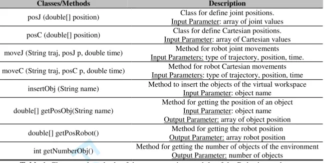
The Robotics package incorporates high-level functions for virtual programming issues which permit final users of the VL to program, compile and execute complex tasks in the robotic VL. The actions are described using the Java language, whereby final users can create variables, mathematical operations and objects in this language. The programming module implements specific classes and methods for both robot simulation and object interaction. For a detailed description of the available classes and methods see Table 1. The Robotics module of EjsRL provides a function which calls to the Java compiler and generates the binary code that is executed in the virtual robotic world. Thus, the compilation and execution of this Java code only requires the Java Development Kit (see Appendix A).
Figure 12 shows the implementation of virtual programming features in the VL proposed. It is only necessary to create an interactive user interface in the Ejs’ view view (like a dialog panel including a text filed and a button), to insert Java code, and to carry out the compilation and execution of this Java code using the functions provided by the Robotics module of EjsRL (see Figure 12).
The common structure that users must follow to program a specific task is the following: - Declaration of the positions (joint or Cartesian) and time in form of double variables and arrays. 3 4 5 6 7 8 9 10 11 12 13 14 15 16 17 18 19 20 21 22 23 24 25 26 27 28 29 30 31 32 33 34 35 36 37 38 39 40 41 42 43 44 45 46 47 48 49 50 51 52 53 54 55 56 57 58 59
For Peer Review
- Creation of the positions objects by means of classes posJ and posC. The parameters for these objects are the variables and arrays initialized before.
- Insertion of the virtual objects located in the workspace with the same name given in the Ejs view. - Declaration of the movement commands. Users can employ the methods moveJ and moveC for joint and Cartesian movements. The parameters for these methods are the objects posJ and posC created before.
Figure 13 shows a programming experiment which consists of doing a pick-and-place operation of a virtual object located in the table. As mentioned before, there are three different parts in the program’s structure: 1) declarations of the positions; 2) creation of the objects posJ; 3) insertion of the virtual objects; and 4) definition of the order movements. In these last methods, users can specify the trajectory that they want to use. In the example proposed, the task is performed by means of synchronous trajectories (parameter “Syn” in the method moveJ). Figure 13 also shows the states of the virtual robot during the execution of the pick-and-place experiment. The image sequence represents each of the joint positions programmed in the routine.
4. Advanced features
The Robotics package of EjsRL contains some functions for the development of image processing algorithms within Ejs’ environment. These functions implement image feature extraction algorithms in order to add sensor features in the robotic VL.
In order to show this advanced property, authors implement a computer vision algorithm in the virtual robotic environment previously created. The aim is to perform an Eye-In-Hand (EIH) vision servoing control, a complex robotic algorithm. A visual servoing is a well known approach to guide a robot by using visual information. The two main types of visual servoing techniques are position-based and image-based [18]. The first one uses 3-D visually-derived information when making motion control 3 4 5 6 7 8 9 10 11 12 13 14 15 16 17 18 19 20 21 22 23 24 25 26 27 28 29 30 31 32 33 34 35 36 37 38 39 40 41 42 43 44 45 46 47 48 49 50 51 52 53 54 55 56 57 58
For Peer Review
decisions. The second one performs the task by using information obtained directly from the image. In this section an image-based visual servoing system is implemented using Ejs and EjsRL.
A visual servoing control task can be described by an image function, et, which must be regulated to 0:
* t
=
-e
s s
(3)
where s = (f1, f2, … fM) is a M x 1 vector containing M visual features observed at the current state, while s* = (f1*, f2*, … fM*) denotes the visual features values at the desired state, i.e. the image features observed at the desired robot location. In Figure 14a) the eye-in-hand camera system is shown within virtual robotic environment where a virtual camera is located at the end-effector of the robot. In Figure 14b), an example of a visual servoing task is represented. This image shows the initial and desired image features from the camera point of view.
In a visual-servo control algorithm, the interaction matrix, Ls, relates the variations in the image (s&) with the variation in the velocity of the camera respect to the scene (r&), i. e.:
s
⋅
s = L r
&
&
(4)
where
r
&
indicates the velocity of the camera. By imposing an exponential decrease of et (e
&
t= −
λ
1 te
) it is possible to obtain the following control action for a classical image-based visual servoing:(
*)
c =−λ1ˆs − +
v L s s
(5) where
L
ˆ
+sis an approximation of the interaction matrix Ls [18].In order to implement this advanced experiment, firstly it is necessary to obtain a view projection from the end effector of the robot. For that end, Ejs has an option which allows users to obtain the projection of the virtual camera included in the 3D robotic environment. Figure 15 shows the projection 3 4 5 6 7 8 9 10 11 12 13 14 15 16 17 18 19 20 21 22 23 24 25 26 27 28 29 30 31 32 33 34 35 36 37 38 39 40 41 42 43 44 45 46 47 48 49 50 51 52 53 54 55 56 57 58 59
For Peer Review
of the EIH virtual camera in the window “Virtual Camera”. Secondly, this projection must be processed in order to extract the corner features of the object. Figure15 also shows the Java code which computes corner detection in the virtual camera’s image using the SUSAN algorithm [19], a method implemented in the EjsRL library. The classes ImageObject and ImageFunction belong to EjsRL library and they are used to develop image processing algorithms. In the window “Virtual Image”, it can be seen the point features detected of the virtual object (see Figure 15).
Figure 16 shows the final application developed which implements a visual-servoing algorithm that uses points as visual features. In the upper part of the Figure 16, the window “Virtual Camera” projects the virtual workspace of the EIH virtual camera. In the window “Virtual Image”, it can be seen the corner features detected using the SUSAN algorithm. The application also shows the 3D trajectory performed by the virtual robot to reach the final desired features s* (see equations (3) and (5)). Finally, the evolution of the velocity module is showed in order to validate the correct convergence of the visual servo task since the velocity described in (5) must be 0 at the end of the trajectory (the image error (3) is regulated to 0).
5. Educational use of the software platform
Developing a VL helps students connect the mathematical model to the real system they are trying to simulate [2]. In addition, designing and performing simulation experiments one-self magnifies student confidence in managing modeling techniques and makes them active players in the learning process, which increases motivation to further learning [4]. For these reasons, authors of this paper have been used this approach to allow both undergraduate/postgraduate students and teachers developing their own robotic VLs. 3 4 5 6 7 8 9 10 11 12 13 14 15 16 17 18 19 20 21 22 23 24 25 26 27 28 29 30 31 32 33 34 35 36 37 38 39 40 41 42 43 44 45 46 47 48 49 50 51 52 53 54 55 56 57 58
For Peer Review
At the moment, the software platform presented is being used in the course Robots and Sensorial Systems in the Computer Science Engineering degree at the University of Alicante. This course is organized so that robotic concepts are presented in the theoretical lessons in a manner that is directly parallel to the creation of a robotic VL using Ejs and EjsRL to make these concepts more concrete. Moreover, the software platform is being used by Computer Science students for their Final Project to fulfil their major requirements, by PhD students for their research experiments and by teachers for developing learning material.
5.1 Course organization
Computer science engineers typically have not background in Robotics. As commented, to solve this handicap, the course is structured so that students develop the robotic VL in a parallel way that they learn Robotics theory. In particular, the theoretical classes of the courses are organized as follows:
1) Mathematical tools for spatial transformation in Robotics 2) Manipulator kinematics
3) Robot dynamics
4) Robot programming languages
The practical experiments employ the software platform presented here. The educational methodology proposed for practises is based on the following criteria:
1) Students have to choose a specific real robotic system and to compute its DH parameters. Moreover, the 3D links of the robot must be modeled by means of CAD design software. These 3D solids are exported to VRML/3DS files for the Ejs’ environment.
2) Students are required to include the kinematics simulation in the VL.
3) Students must develop several path planning algorithms for the robot chosen. 4) Students must implement dynamics and programming features in the VL. 3 4 5 6 7 8 9 10 11 12 13 14 15 16 17 18 19 20 21 22 23 24 25 26 27 28 29 30 31 32 33 34 35 36 37 38 39 40 41 42 43 44 45 46 47 48 49 50 51 52 53 54 55 56 57 58 59
For Peer Review
5.2 Evaluation of the teaching technique and educational results
In order to evaluate the teaching technique, a study was carried out in order to verify its usefulness and efficiency. Questionnaire items were focused on two main issues:
1) Perception of the students about if they have learnt Robotics in the course and the degree of agreement with some statements about the effectiveness of the course (I1).
2) The development of their own VLs in the learning process using Ejs and EjsRL (I2).
Table 2 shows both the questionnaire made and the results obtained over 30 students from the course. Responses were rated on a five point Likert scale ranking from strongly agree (1) to strongly disagree (5). Analyzing the results, more than half of the students think that they have learnt more in this course than in an another course about Robotics. In addition, they recommended the course to other Computer Science students and the homework were helpful (issue I1). Moreover, almost all of students think that the VL is an efficient tool in the learning process and designing his/her own robotic VL using Ejs and EjsRL has been helpful in understanding the robotic concepts and to encourage them to learn Robotics (issue I2).
In addition the survey, a comparison between the final marks of the students who coursed the subject using the software tool presented in this paper (academic year 2010) and the student who not (academic year 2009), was performed. As can be seen in Figure 17, there is a high number of students who got better marks with the use of the software platform: 20% more with A qualification and 10% more with B qualification. The global qualification between two years increased from 7.1 to 8.3.
Finally, in the questionnaire performed, students were encouraged to write comments regarding the course. Most of the comments were such as: “I liked the emphasis on the simulations results rather than the mathematical model of the robotic system” or “This course has provided me with a lot of insight 3 4 5 6 7 8 9 10 11 12 13 14 15 16 17 18 19 20 21 22 23 24 25 26 27 28 29 30 31 32 33 34 35 36 37 38 39 40 41 42 43 44 45 46 47 48 49 50 51 52 53 54 55 56 57 58
For Peer Review
into how to model and design a robotic VL” or “I recommend this course to other Computer Science students who are interested in Robotics”.
5.3 Some final VLs developed
Computer Science students were able to develop advanced VLs of real robotic systems such as a Barrett Hand [20] (Figure 18a), a Scorbot RX of 5 DOF (Figure 18b) and a Mitsubishi PA-10 of 6 DOF (Figure 18c). A PhD student developed a virtual multi-robot system composed by two manipulators, since EjsRL allows users the instantiation of different robot objects in the Ejs’ environment (Figure 18e). Finally, a teacher was able to create a visual servo control of redundant robot of 7 DOF (Figure 18d). These complex VLs can be seen at www.aurova.ua.es/rcv.
6. Conclusions
In this paper, a free Java-based software platform for the creation of advanced robotic and computer vision applications has been presented. This new tool is composed by two blocks: 1) a high-level Java library called EjsRL, which provides a complete functional framework for modeling and simulation of robotic systems; 2) Ejs, an open-source tool which provides full graphical interface support. The integration of both parts permits to create complex and advanced robotic applications in an easy way.
EjsRL allows users to model complex robotic systems within Ejs. For modeling arbitrary serial-link manipulators, users only have to specify their DH parameters and their physical properties. Then, the Java platform creates an object which has embedded all the robot behaviour (kinematics, dynamics, programming, etc.). The user-friendly interface of Ejs enables users to easily and quickly create advanced Java applications. In addition to its full computer graphical support, this software provides several advanced features such as VRML, 3DS and OBJ extern file importation. All these features are complemented with a wide range of objects and operations for Robotics provided by EjsRL. Thus, the 3 4 5 6 7 8 9 10 11 12 13 14 15 16 17 18 19 20 21 22 23 24 25 26 27 28 29 30 31 32 33 34 35 36 37 38 39 40 41 42 43 44 45 46 47 48 49 50 51 52 53 54 55 56 57 58 59
For Peer Review
approach presented is very suitable to develop research and educational applications in the Robotics field apart from adding novel features that are not found in other toolboxes available today.
The paper has shown the simple steps to design and develop a complete VL for Robotics education. The implementation methodology of all the Robotics algorithms has been described as an easy development which can be done by any user. In addition, a teaching methodology was carried on using the presented approach. This educational framework required that students to develop their own robotic VLs to help them learn and retain Robotics. The results obtained show that students think that designing his/her own robotic VL using Ejs and EjsRL has been helpful in understanding the robotic concepts and to encourage them to learn Robotics. Finally, it is important to remark that different users (students and teachers) were able to develop high-level applications which illustrate the powerful of the proposed software platform.
Acknowledgments
This work is supported by the Spanish Ministry of Education and Science through the research project DPI2008-02647 02647 as well as the "Technology & Educational Innovation Vicepresident Office” of the University of Alicante through the aid "Technologic & Educative Research Groups".
Appendix A
EjsRL and EjsEjsRL can be obtained from www.aurova.ua.es/rcv. In this web page there is a lot of information about how to use the library and readers can execute all the examples showed in the paper. Ejs can be downloaded from http://fem.um.es/EjsWiki/ where readers can experiment with a lot of simulations developed with this software. In order to use them in any operative system, it is necessary to install two 3 4 5 6 7 8 9 10 11 12 13 14 15 16 17 18 19 20 21 22 23 24 25 26 27 28 29 30 31 32 33 34 35 36 37 38 39 40 41 42 43 44 45 46 47 48 49 50 51 52 53 54 55 56 57 58
For Peer Review
Java environments: JDK (Java Development Kit) 1.6 and Java 3D 1.5 or higher, higher, which are available for many platforms including MS. Windows and Unix based systems.
References
[1] V. Potkonjak, M. Vukobratović, K. Jovanović and M. Medenica, Virtual mechatronic/robotic laboratory – a step further in distance learning, Computers & Education 55 (2010), 465-475.
[2] S. Dormido, Control learning: Present and future, Annual Reviews in Control 28 (2004), 115–136. [3] C. Martín-Villalba, A. Urquía and S. Dormido, Development of an Industrial Boiler Virtual-Lab for Control Education Using Modelica (in press), Computer Applications in Engineering Education. DOI: 10.1002/cae.20449.
[4] T. Murphey, Teaching rigid body mechanics using student-created virtual environments, IEEE Transations on Education 51 (2007), 45-52.
[5] S. Dormido, R. Dormido, J. Sánchez and N. Duro, The role of interactivity in control learning, International Journal of Engineering Education 21 (2005), 1122–1133.
[6] “RoboWorks Software”. http://www.newtonium.com/. 2010. [7] “Robot Assist Software”. http://www.kinematics.com/. 2010. [8] “Easy-ROB Software”. http://www.easy-rob.com/. 2010.
[9] R. Gourdeau, Object-oriented programming for robotic manipulator simulation, IEEE Robotics and Automation Magazine 4 (1997), 21-29.
[10] A. Breijs, B. Klaassens and R. Babuska, “Matlab Design Environment for Robotic Manipulators,” Proceedings of the 16th IFAC World Congress, Prague, 2005.
[11] R. Falconi and C. Melchiorri, “Roboticad: An Educational Tool for Robotics,” Proceedings of the 17th IFAC World Congress, Seoul, 2008.
[12] P. Corke, A Robotics Toolbox for MATLAB, IEEE Robotics and Automation Magazine 3 (1996), 24-32. 3 4 5 6 7 8 9 10 11 12 13 14 15 16 17 18 19 20 21 22 23 24 25 26 27 28 29 30 31 32 33 34 35 36 37 38 39 40 41 42 43 44 45 46 47 48 49 50 51 52 53 54 55 56 57 58 59
For Peer Review
[13] “Java Sun Website”. http://java.sun.com. 2010.[14] F. Esquembre, Easy Java simulations: A software tool to create scientific simulations in Java, Computer in Physics Communications 156 (2004), 199-204.
[15] C. Jara, F. Esquembre, F. Candelas, F. Torres and S. Dormido, “New features of Easy Java Simulations for 3D modeling,” Proceedings of 8th IFAC Symposium on Advances in Control Education, Kumamoto, 2009.
[16] J. Denavit and R. Hartenberg,. A kinematic notion for lower-pair mechanisms based on matrices, Journal of Applied Mechanisms 22 (1955), 215–221.
[17] L. Sciavicco and B. Siciliano, Modeling and Control of Robot Manipulators.2nd Ed. Springer Verlag. London. 2005.
[18] F. Chaumette and S. Hutchinson, Visual servo control I. Basic approaches, IEEE Robotics and Automation Magazine 13 (2006), 82-90.
[19] S. Smith and J. Brady, SUSAN: a new approach to low level image processing, International Journal of Computer Vision 23 (1997), 45-78.
[20] “Barrett Technology” (Barrett Hand). http://www.barrett.com/. 2010. 3 4 5 6 7 8 9 10 11 12 13 14 15 16 17 18 19 20 21 22 23 24 25 26 27 28 29 30 31 32 33 34 35 36 37 38 39 40 41 42 43 44 45 46 47 48 49 50 51 52 53 54 55 56 57 58
For Peer Review
Figure and Table captions
Figure 1. Architecture of the software platform. Figure 2. Set-up of Ejs’ environment.
Figure 3. DH parameters and skeleton representation of the Scara robot.
Figure 4. Java code to be included in the VL model in order to create a 4 DOF Scara robot. Figure 5. Design of the view interface of the robot arm proposed and its workspace. Figure 6. Implementation of the forward kinematics simulation for the Scara robot. Figure 7. Implementation of the inverse kinematics simulation for the Scara robot.
Figure 8. ODEs of basic robot motion and Java code to program a 4-3-4 polynomial trajectory. Figure 9. Simulation of the 4-3-4 polynomial path planning algorithm in the VL proposed. Figure 10. Implementation of the inverse dynamics simulation with an external force. Figure 11. Simulation of the robot dynamics.
Figure 12. Implementation of virtual programming features in the VL.
Figure 13. Java code of the pick-and-place experiment and states of the virtual robot during the execution of this programming experiment.
Figure 14. a) Eye-in-hand configuration b) Current and desired visual features in an image based visual servoing task.
Figure 15. Implementation of the point detection of the EIH virtual camera projection. Figure 16. Simulation developed of a visual servoing task using point features. Figure 17. Comparison of students marks between the academic years 2009 and 2010.
Figure 18. Advanced robotic VLs developed by the students and teachers: a) the Barrett Hand simulation; b) a Scorbot RX of 5 DOF; c) a Mitsubishi PA-10 of 6 DOF; d) a visual servo control of a redundant 7 DOF robot manipulator; e) a multi-robot system.
Table 1. Classes and methods of the programming module of the Robotics package. Table 2. Student questionnaire and results obtained in percentage of agreement. 3 4 5 6 7 8 9 10 11 12 13 14 15 16 17 18 19 20 21 22 23 24 25 26 27 28 29 30 31 32 33 34 35 36 37 38 39 40 41 42 43 44 45 46 47 48 49 50 51 52 53 54 55 56 57 58 59
For Peer Review
Architecture of the software platform 164x101mm (150 x 150 DPI) 3 4 5 6 7 8 9 10 11 12 13 14 15 16 17 18 19 20 21 22 23 24 25 26 27 28 29 30 31 32 33 34 35 36 37 38 39 40 41 42 43 44 45 46 47 48 49 50 51 52 53 54 55 56 57 58
For Peer Review
Set-up of Ejs’ environment 196x96mm (150 x 150 DPI) 3 4 5 6 7 8 9 10 11 12 13 14 15 16 17 18 19 20 21 22 23 24 25 26 27 28 29 30 31 32 33 34 35 36 37 38 39 40 41 42 43 44 45 46 47 48 49 50 51 52 53 54 55 56 57 58 59
For Peer Review
DH parameters and skeleton representation of the Scara robot 198x106mm (150 x 150 DPI) 3 4 5 6 7 8 9 10 11 12 13 14 15 16 17 18 19 20 21 22 23 24 25 26 27 28 29 30 31 32 33 34 35 36 37 38 39 40 41 42 43 44 45 46 47 48 49 50 51 52 53 54 55 56 57 58
For Peer Review
Java code to be included in the VL model in order to create a 4 DOF Scara robot 261x108mm (150 x 150 DPI) 3 4 5 6 7 8 9 10 11 12 13 14 15 16 17 18 19 20 21 22 23 24 25 26 27 28 29 30 31 32 33 34 35 36 37 38 39 40 41 42 43 44 45 46 47 48 49 50 51 52 53 54 55 56 57 58 59
For Peer Review
Design of the view interface of the robot arm proposed and its workspace 140x140mm (150 x 150 DPI) 3 4 5 6 7 8 9 10 11 12 13 14 15 16 17 18 19 20 21 22 23 24 25 26 27 28 29 30 31 32 33 34 35 36 37 38 39 40 41 42 43 44 45 46 47 48 49 50 51 52 53 54 55 56 57 58
For Peer Review
Implementation of the forward kinematics simulation for the Scara robot 423x319mm (150 x 150 DPI) 3 4 5 6 7 8 9 10 11 12 13 14 15 16 17 18 19 20 21 22 23 24 25 26 27 28 29 30 31 32 33 34 35 36 37 38 39 40 41 42 43 44 45 46 47 48 49 50 51 52 53 54 55 56 57 58 59
For Peer Review
Implementation of the inverse kinematics simulation for the Scara robot 222x159mm (150 x 150 DPI) 3 4 5 6 7 8 9 10 11 12 13 14 15 16 17 18 19 20 21 22 23 24 25 26 27 28 29 30 31 32 33 34 35 36 37 38 39 40 41 42 43 44 45 46 47 48 49 50 51 52 53 54 55 56 57 58
For Peer Review
ODEs of basic robot motion and Java code to program a 4-3-4 polynomial trajectory 221x156mm (150 x 150 DPI) 3 4 5 6 7 8 9 10 11 12 13 14 15 16 17 18 19 20 21 22 23 24 25 26 27 28 29 30 31 32 33 34 35 36 37 38 39 40 41 42 43 44 45 46 47 48 49 50 51 52 53 54 55 56 57 58 59
For Peer Review
Simulation of the 4-3-4 polynomial path planning algorithm in the VL proposed 344x206mm (96 x 96 DPI) 3 4 5 6 7 8 9 10 11 12 13 14 15 16 17 18 19 20 21 22 23 24 25 26 27 28 29 30 31 32 33 34 35 36 37 38 39 40 41 42 43 44 45 46 47 48 49 50 51 52 53 54 55 56 57 58
For Peer Review
Implementation of the inverse dynamics simulation with an external force 252x113mm (150 x 150 DPI) 3 4 5 6 7 8 9 10 11 12 13 14 15 16 17 18 19 20 21 22 23 24 25 26 27 28 29 30 31 32 33 34 35 36 37 38 39 40 41 42 43 44 45 46 47 48 49 50 51 52 53 54 55 56 57 58 59
For Peer Review
Simulation of the robot dynamics 264x206mm (96 x 96 DPI) 3 4 5 6 7 8 9 10 11 12 13 14 15 16 17 18 19 20 21 22 23 24 25 26 27 28 29 30 31 32 33 34 35 36 37 38 39 40 41 42 43 44 45 46 47 48 49 50 51 52 53 54 55 56 57 58
For Peer Review
Implementation of virtual programming features in the VL 132x150mm (150 x 150 DPI) 3 4 5 6 7 8 9 10 11 12 13 14 15 16 17 18 19 20 21 22 23 24 25 26 27 28 29 30 31 32 33 34 35 36 37 38 39 40 41 42 43 44 45 46 47 48 49 50 51 52 53 54 55 56 57 58 59
For Peer Review
Java code of the pick-and-place experiment and states of the virtual robot during the execution of this programming experiment
167x191mm (150 x 150 DPI) 3 4 5 6 7 8 9 10 11 12 13 14 15 16 17 18 19 20 21 22 23 24 25 26 27 28 29 30 31 32 33 34 35 36 37 38 39 40 41 42 43 44 45 46 47 48 49 50 51 52 53 54 55 56 57 58
For Peer Review
a) Eye-in-hand configuration; b) Current and desired visual features in an image based visual servoing task 225x124mm (150 x 150 DPI) 3 4 5 6 7 8 9 10 11 12 13 14 15 16 17 18 19 20 21 22 23 24 25 26 27 28 29 30 31 32 33 34 35 36 37 38 39 40 41 42 43 44 45 46 47 48 49 50 51 52 53 54 55 56 57 58 59
For Peer Review
Implementation of the point detection of the EIH virtual camera projection 293x120mm (150 x 150 DPI) 3 4 5 6 7 8 9 10 11 12 13 14 15 16 17 18 19 20 21 22 23 24 25 26 27 28 29 30 31 32 33 34 35 36 37 38 39 40 41 42 43 44 45 46 47 48 49 50 51 52 53 54 55 56 57 58
For Peer Review
Simulation developed of a visual servoing task using point features 235x147mm (150 x 150 DPI) 3 4 5 6 7 8 9 10 11 12 13 14 15 16 17 18 19 20 21 22 23 24 25 26 27 28 29 30 31 32 33 34 35 36 37 38 39 40 41 42 43 44 45 46 47 48 49 50 51 52 53 54 55 56 57 58 59
For Peer Review
Comparison of students marks between the academic years 2009 and 2010 193x101mm (150 x 150 DPI) 3 4 5 6 7 8 9 10 11 12 13 14 15 16 17 18 19 20 21 22 23 24 25 26 27 28 29 30 31 32 33 34 35 36 37 38 39 40 41 42 43 44 45 46 47 48 49 50 51 52 53 54 55 56 57 58
For Peer Review
Advanced robotic VLs developed by the students and teachers: a) the Barrett Hand simulation; b) a Scorbot RX of 5 DOF; c) a Mitsubishi PA-10 of 6 DOF; d) a visual servo control of a redundant 7
DOF robot manipulator; e) a multi-robot system 225x160mm (150 x 150 DPI) 3 4 5 6 7 8 9 10 11 12 13 14 15 16 17 18 19 20 21 22 23 24 25 26 27 28 29 30 31 32 33 34 35 36 37 38 39 40 41 42 43 44 45 46 47 48 49 50 51 52 53 54 55 56 57 58 59
For Peer Review
Classes/Methods Description
posJ (double[] position) Class for define joint positions. Input Parameter: array of joint values posC (double[] position) Class for define Cartesian positions.
Input Parameter: array of Cartesian values moveJ (String traj, posJ p, double time) Method for robot joint movements
Input Parameters: type of trajectory, position, time. moveC (String traj, posC p, double time) Method for robot Cartesian movements
Input Parameters: type of trajectory, position, time insertObj (String name) Method to insert the objects of the virtual workspace
Input Parameter: object name double[] getPosObj(String name)
Method for getting the position of an object Input Parameter: object name Output Parameter: array of object position double[] getPosRobot() Method for getting the robot position
Output Parameter: array robot position
int getNumberObj() Method for getting the number of objects of the environment Output Parameter: number of objects
Table 1. Classes and methods of the programming module of the Robotics package.
3 4 5 6 7 8 9 10 11 12 13 14 15 16 17 18 19 20 21 22 23 24 25 26 27 28 29 30 31 32 33 34 35 36 37 38 39 40 41 42 43 44 45 46 47 48 49 50 51 52 53 54 55 56 57 58 59 60
For Peer Review
Table 2. Student questionnaire and results obtained in percentage of agreement.
Question Issue %Strongly
agree %Agree %Neutral %Disagree
%Stringly disagree Have you learnt more in
the course than in another course about Robotics you have taken?
I1 50 30 15 5 0
Do you think that homework has been helpful in understanding the material?
I1 62.5 20 15 2.5 0
Do you recommend the course to other Computer Science students?
I1 57.5 30 12.5 0 0
Do you feel that you can use robotic concepts learnt in practical situations?
I1 42.5 30 22.5 5 0
Do you think that the VLs help you to understand concepts about robotic systems?
I2 55 32.5 12.5 0 0
Do you think designing your own robotic VL have
been helpful in
understanding the mathematical model of a robot manipulator?
I2 62.5 25 12.5 0 0
Have you encouraged learning more about Robotics the development of your own VL using Ejs and EjsRL? I2 57.5 30 7.5 5 0 3 4 5 6 7 8 9 10 11 12 13 14 15 16 17 18 19 20 21 22 23 24 25 26 27 28 29 30 31 32 33 34 35 36 37 38 39 40 41 42 43 44 45 46 47 48 49 50 51 52 53 54 55 56 57 58 59 60