University of South Florida
Scholar Commons
Graduate Theses and Dissertations Graduate School3-14-2017
Initial Comparative Empirical Usability Testing for
the Collaborative Authentication System
Kim Bursum
University of South Florida, [email protected]
Follow this and additional works at:http://scholarcommons.usf.edu/etd
Part of theComputer Sciences Commons
This Thesis is brought to you for free and open access by the Graduate School at Scholar Commons. It has been accepted for inclusion in Graduate Theses and Dissertations by an authorized administrator of Scholar Commons. For more information, please [email protected].
Scholar Commons Citation
Bursum, Kim, "Initial Comparative Empirical Usability Testing for the Collaborative Authentication System" (2017).Graduate Theses and Dissertations.
Initial Comparative Empirical Usability Testing for the Collaborative Authentication System
by
Kimberly S. Bursum
A thesis submitted in partial fulfillment of the requirements for the degree of Master of Science in Computer Science Department of Computer Science and Engineering
College of Engineering University of South Florida
Major Professor: Jay Ligatti, Ph.D. Dmitry Goldgof, Ph.D.
Xinming Ou, Ph.D. Date of Approval:
March 9, 2017
Keywords: device authentication, smart devices, token communication, access control, public key cryptography
DEDICATION
I lovingly dedicate this thesis work to L.B. You are the center of my universe and always will be.
ACKNOWLEDGMENTS
I would like to give special thanks to my advisor, Dr. Jay Ligatti, for his time, wisdom and kindness in general and especially on this project. I also appreciate Dr. Dmitry Goldgof for his many insightful suggestions. Finally, I greatly enjoyed working with J.B. and Shamaria and especially Cagri, I learned so much from all of you! I’ve never really seen inventing from this perspective, thank you for letting me be a part of the adventure.
i
TABLE OF CONTENTS
LIST OF TABLES iii
LIST OF FIGURES iv
ABSTRACT v
CHAPTER 1: INTRODUCTION 1
1.1 Authentication in a Computer Context 1
1.2 Authentication Factors 2
1.3 Authentication Threats 3
CHAPTER 2: MOTIVATION FOR USABILITY TESTING AND RELATED WORK 4 2.1 Unusable Security Systems are Not Secure 4
2.2 Reasons that Poor Usability Occurs 5
2.2.1 Conflict in Goals and Motivations Between Designer/User 5
2.2.2 Divergent Expectations 6
2.2.3 Lack of Expertise/Training 7
2.3 Usability Now Seen to Add Value 8
2.4 Testing Early and Often in the Design Process 8
2.4.1 Usability Laboratory 9
2.4.2 Heuristic Analysis 10
2.4.3 General Types of Usability Testing 10 2.4.4 Subjective User Testing 11
CHAPTER 3: THE COLLABORATIVE AUTHENTICATION SYSTEM 12
3.1 History of the Project 13
3.2 Co-authentication Functionality 13 3.2.1 Step 1 15 3.2.2 Step 2 15 3.2.3 Step 3 15 3.2.4 Step 4 16 3.2.5 Step 5 16 3.2.6 Step 6 18
3.3 Advantages/Disadvantages of the Co-authentication System 18 3.4 New Bluetooth Token Communication Channel 19 3.4.1 Co-authentication Collaboration 19
3.4.2 Send Activity 20
ii
CHAPTER 4: PROPOSED EMPIRICAL TESTING DESIGN 22
4.1 Test 1 24
4.1.1 Summary of Functionality 24
4.1.2 Experimental Set-up 25
4.1.3 Operation of Experiment 25
4.1.4 Detail of the Code 27
4.1.4.1 Login Screen Appearance 27 4.1.4.2 Login Screen Data Collection 28
4.2 Test 2 30
4.2.1 Summary of Functionality 30
4.2.2 Experimental Setup 31
4.2.3 Operation of Experiment 32
4.2.4 Detail of Code 34
4.2.4.1 Login Screen Appearance 35 4.2.4.2 Data Collection 36 4.3 Test 3 37 4.3.1 Summary of Functionality 37 4.3.2 Experimental Setup 37 4.3.3 Operation of Experiment 38 4.3.4 Detail of Code 38 4.4 Test 4 39
4.4.1 Code for the Button Function 39 4.4.2 Operational Differences from Test 3 39
CHAPER 5: CONCLUSION AND FUTURE WORK 41
LIST OF REFERENCES 43
iii
LIST OF TABLES
iv
LIST OF FIGURES
Figure 3.1 Co-authentication Protocol 14
Figure 4.1 Test 1 Login Screen 26
Figure 4.2 Test 1 Error Message 27
Figure 4.3 Test 2 Login Screen 32
v
ABSTRACT
The Collaborative Authentication (co-authentication) system is an authentication system that relies on some or all members of a pre-registered set of secure hardware tokens being
concurrently present to an authentication server at the moment of authentication. Previous researchers have compared various embodiments of the co-authentication system to each other including using Quick Response (QR) codes/cellphone cameras and Near Field Communication (NFC) between tokens. This thesis concerns the initial design and implementation of empirical comparative testing mechanisms between one embodiment of the co-authentication system and other commonly used authentication systems. One contribution is the simulated standard user ID and password login in a computer browser and a simulated RSA SecureID ® one time password (OTP) and login with embedded usability testing mechanisms. Another contribution is the development and implementation of a new Bluetooth communication functionality between tokens. A third contribution is the addition of usability testing mechanisms to two versions of this new functionality.
1
CHAPTER 1 INTRODUCTION
Authentication is an age-old problem. The word authentication is derived from the Greek: αὐθεντικός authentikos, "real, genuine” [27]. While identification is the making of a claim or offering proof of identity, authentication is the verification and confirmation of that proof. Generally, the owner of a resource (rights holder) has an interest in controlling who is able to see or use their resource to protect his/her ownership rights and uses authentication for this purpose. It is important to him/her to ensure that a person or entity requesting access is who they represent themselves to be in order to be able to properly grant or deny access to the
intended recipient.
1.1 Authentication in a Computer Context
In cybersecurity, authentication is the automated verification of the identity, source or process (user and/or device) who is requesting access to data, applications or other resources stored in a computer accessible medium. When it receives a request for access from a user’s computer, the rights holder’s computer requests credentials from the user and the credentials provided are compared to those on file in a database of authorized users' information on a local operating system or within an authentication server. If the credentials match, the process is completed and the user is granted authorization for access.
2
In the modern highly networked world, the quantity of requests for access occurs on a massive scale and each request must be handled quickly and accurately every time. The consequences of just one access-control failure with an active adversary may be total
compromise of the system and theft or vandalism of the resource (such as data corruption or denial of service). A trust relationship may be established for further interactions if the authentication is successful. Access control, including authentication, protects the traditional security attributes of confidentiality, integrity and availability of information and also other
important aspects including accountability, non-repudiation and reliability [20].
1.2 Authentication Factors
There are three general categories of authentication methods: – what-you-have (i.e. hardware or software tokens),
– what-you-know (i.e. passwords, PINs) or
– what-you-are (i.e. physical traits for biometric measurement, location).
These are known as the authentication factors [37]. “One factor authentication” means if one factor is verified then access is granted. If two different factors have to be independently verified then this is “two factor authentication” and is theoretically significantly more secure because an attacker will have to independently compromise both factors. What-you-know, specifically a user-memorized password typed in to a computer log-in screen upon request, is the most common single factor used in computer user authentication because this method is easy and cheap to implement by the system owner and is secure enough for low and medium level
security applications if used correctly. Cryptographically signed certificates with providence from trusted authorities (similar to an evidence chain of custody) have been found to be useful
3
for authentication for higher security needs. Public key cryptography uses computationally complex mathematical functions that are impractical to invert to transform digital data for encrypted transmittal.
1.3 Authentication Threats
By design, digital data is easy to copy and manipulate and computer networks facilitate the flow of digital information. The multitude of security vulnerabilities and exposures to networked computers are only limited by the imaginations, technical capability and motivation of attackers. Attack vectors exist for hardware and software and there are multiple taxonomies for organizing these. Some common access control attack vectors are phishing, worms, viruses, social engineering, Trojan horse, physical theft and denial of service. Some well-known access control systems include: password, PIN, challenge response, security question, ID card, security token (hardware or software), biometric (fingerprint, retinal pattern signature, face, voice, typing pattern, walk, location etc.)
One important consideration is that authentication security needs to be proportional to the value of what is protected. In a resource constrained world, attackers generally have a profit model and spend their resources targeting the highest value users and files. There is wide variance in cost in both time and money to individuals and organizations of access control systems. It is highly inefficient and a poor use of highly skilled resources to just blanketly maximize all security settings without evaluating actual security risks. Security models must be intelligently designed to maximize effectiveness and efficiency [28].
4
CHAPTER 2
MOTIVATION FOR USABILITY TESTING AND RELATED WORK
Usability is defined as “the extent to which a product can be used by specified users to achieve specified goals with effectiveness, efficiency and satisfaction in a specified context of use” [20]. In other words, usability is the degree to which a product or service meets a user’s needs [1]. A system’s effectiveness relates to whether it works for its intended purpose. The primary purpose of access control systems is to protect digital data from falling into the wrong hands either inadvertently or by intentional theft. The two failure states are 1) if an unauthorized person obtains access or 2) if an authorized person is unable to obtain access. Asymmetrical risks/consequences of the corresponding two failure states usually mean more attention is paid to blocking unauthorized entities.
2.1 Unusable Security Systems are Not Secure
Unusable security systems, no matter how provably secure in theory they are, fail in their primary purpose if users do not use them as the systems designers anticipate [40].
Passwords, for example, effectively shift the burden of access onto the users who are required to remember intentionally complex and hard to guess passwords for multiple systems. There has been a great deal of research showing that this burden leads to insecure adaptations by users that ultimately result in significantly less security than the system designers expect [1,3,7,8, 9,
5
14,17,19, 21,22, 29, 33, 39,40]. There are also studies showing many people will avoid products with cumbersome security if they can and go to competitors [19,21,22,33].
2.2 Reasons that Poor Usability Occurs
There are many reasons why poor usability occurs. There is a fundamental conflict between the reward structures of users who use the computer to do a primary task and security system designers who are penalized only if security failures happen and suffer no consequences for unusable system design. There are divergent expectations when users see security features only as a hindrance to doing their jobs which may lead them to create work-arounds to the
security features versus security system designers who expect users to prioritize security and take the time to learn and comply with the security tools. There is also mutual lack of
training/expertise in that most users do not understand security failures or see their results and may believe that security is not a daily concern so they make up their own ad hoc security methods and system designers rarely have training or expertise in psychology or human factors or even the context in which their system is used by users so they fail to take these things into consideration in the design.
2.2.1 Conflict in Goals and Motivations Between Designer/User
One significant problem is an inherent conflict in motivation and goals of users versus resource owners and security system designers [10, 14, 21 29]. The user may not see access to the resource as an end in itself – s/he wants easy access to the resource to complete his/her primary task because that is what s/he is rewarded to do [1,3,14,17,21,29]. Since users don’t generally see security risks they don’t see them as much of a problem [1, 8, 21]. In the best case
6
users may see security as a distraction or hindrance imposed on them to protect them from a threat they don’t know exists. The resource owner’s priority is to protect access to the resource and s/he may consider user costs to be collateral or extrinsic to the protection function. Security system designers do not generally have any consequences [14] for unusable design and, like lawyers, are primarily paid to mitigate any risk no matter how small [28]. Security experts may, in fact, overprotect because of their reward structure - they are penalized if problems occur so why take any chances [1, 9, 28, 33].
2.2.2 Divergent Expectations
One of the biggest problems for the user is any system or tool clashing with their expectations of how it should work [40]. Users may also be confused when they see
disagreement among experts and this may give them doubts about the accuracy of any security information. They see many false positives such as certificate configuration errors and the experts tell them to just “click through” those because they are not “real” problems. The users also may see many things that to the careless reader, can be confused for security warnings such as click-wrap agreements and may get dialog fatigue.
Some computer system designers see usability as merely “interface” or “common sense” and see themselves as average users [3, 22, 40]. This is rarely the case because designers self-select for a specific type of intelligence, reasoning ability and diligence and are not
necessarily representative of general population. There also may be cultural differences. System designers may get frustrated by “stupid” users and may see their task as “idiot proofing”.
Designers are very close to their design and no one, no matter how intelligent, can truly see their own work objectively. Generally designers work in small teams. There are many many users
7
and the best designer can’t possibly be as smart as a large, motivated, diverse collective intelligence (this phenomenon is known as hive-mind or crowdsourcing).
2.2.3 Lack of Expertise/Training
Users generally do not understand security risks. They are not told details by the experts because, generally speaking, many users don’t care but also because they wouldn’t understand the risks unless they are translated into specific guidance. It takes time and skilled manpower to translate risks into specific security guidance and most companies want designers to design not “waste their time” translating. Another difficulty is the fact that security threats evolve very quickly and it would take more time to translate each one than to just handle the problem and in most cases users will never know the risk existed. Companies are also fearful of exposing weaknesses and may only report a problem if they have to under the most lenient interpretation of reporting law. Companies see security problems as proprietary information and may not want to tell employees who don’t have a need to know because they fear they might leak this information to the market in an uncontrolled manner and hurt the company’s reputation.
Designers are generally not given the tools to be able to gauge the impact of their design choices on “typical” users. It is very rare for computer system developers to have education or training in cognitive psychology, or any brain science and they may not understand the users’ bias, framing, or cognitive load [14, 17, 25]. Very few designers have training in user
expectation management. Even if they did they might not have the mindset to appreciate that users might have a usefully different perspective or in fact have anything valuable to add to the design of a system. Some developers may have poor communication skills and may not have experience communicating with people who are different from themselves. Steve Jobs famously
8
said “A lot of times, people don’t know what they want until you show it to them” [46]. Many designers believe they are lone geniuses creating “art” (and some of them are).
2.3 Usability Now Seen to Add Value
When security software was designed and used only by other technical experts, usability was considered optional or, worst case, a sign of weakness or an insult to your colleague’s intelligence. Usability generally didn’t matter until users became potential customers. It still tends to only be fully studied when usability problems occur [14]. The
process of usability testing is evolving. In the early days there was none; a common attitude was almost ship it and let the market tell us what’s wrong with it. Later, usability was seen as merely a “packaging” activity after all the functional work was done.
Usability testing in agile engineering and software production is widely now seen as a valuable development tool and is done at a smaller scale more frequently in the design process [33]. One guiding principal is that the earlier in the production process that problems are found, the cheaper it is to correct them [22, 33]. Perfect usability of an authentication system from user perspective is when it is invisible, it “just works”. Security features should be proportional to risk, and have minimum disruption to user.
2.4 Testing Early and Often in the Design Process
Usability is greatly improved by usability testing early and often in design process [14, 26, 30]. Usability testing adds the most value if it includes testing the system or product on people who share as many characteristics with potential real users as possible [19, 26, 30]. Optimally usability testing uses classical experimental methodology including development of a
9
hypothesis and controls and experimentation to isolate one variable at a time and the use of samples and statistical modeling to properly infer the results onto the general population [17, 19, 22, 26, 30, 36]. Depending on the stage of product development, other, less costly, usability testing methods may be used but the closer to classical experimental methodology, the more valuable the results.
2.4.1 Usability Laboratory
Experiments are done under controlled conditions in a laboratory and consist of test participants (TPs) being given specific tasks to perform that include using the system or product under testing. Many versions of each experiment are given to each TP – a baseline/control version and as many versions as necessary to isolate and modify one feature at a time to be tested. The test administrators (TAs) include cognitive psychologists who observe the TPs during the experiment and document body language, hesitation, tone of voice and other behavioral clues that may indicate what the TP is thinking (and may not be saying). The laboratory is a mockup office setting, for example, with a believable product and scenario that will induce the TPs to treat it “normally”. The computer that the TP uses contains tracking software that runs in the background to collect keystrokes, event timing, task success rate and other data. The laboratory is equipped with cameras, eye-tracking equipment, one way mirrors and an in-room moderator observing and encouraging the TP to think out loud. Developers are encouraged to attend to see first hand how users see their product. TPs are also given
preliminary questionnaires to enable TAs to categorize them by experience level and
demographics and then subjective questionnaires after each test and then overall asking how well they liked using the product. Depending on the stage of development, resources available and
10
cost of potentially poor usability to the developer, sometimes usability testing is done remotely by crowd sourcing [39] or via virtual world simulations [26] with the obvious tradeoffs of lack of detailed observation and environmental controls [30].
2.4.2 Heuristic Analysis
Cognitive psychologists can also do theoretical usability studies [30]. Some of these include breaking the authentication tasks down into micro-actions and trace different areas of brain usage (i.e. visual working memory, procedural memory, declarative recall, semantic recognition, etc.) used in performing the authentication steps to ensure an optimal mental flow when performing the required steps [14]. Behavioral Psychologists are also able to help in the analysis of a particular authentication model, how bias, framing and cognitive load lead to specific user visualizations and expectations [14, 17, 28, 29]. Some usability experts use keystroke level modeling [17] and the NASA-TLX workload assessment instrument [18, 26] to analyze total user burden [39] in authentication.
2.4.3 General Types of Usability Testing
There are two categories of usability testing: 1) Formative – finding and fixing usability problems or 2) Summative – describing the usability of an application using metrics [30]. Often benchmarks are used for usability comparison and comparisons include different versions of the same product or a competitor’s products [14, 29, 36]. Within subjects design is when the same TPs attempt tasks on all versions and between subjects design is when different sets of users test each version. Results are tabulated immediately and statistically analyzed to accept or reject hypotheses and to determine what variable performed the best and also to ensure statistical
11
significance of findings (confidence interval) and look for causality [30]. The data from many experiments are compared to look for differences in relative variance (ANOVA) [19, 20, 36]. The TPs are also analyzed using skill level and demographics to ensure representativeness (stratified sampling) and randomness. Developers can iteratively make revisions based on new information and continually improve the product’s usability. If the developer is lucky the TPs might get frustrated and demonstrate a cheat or workaround that shows the developer where the holes in the system security are located. Companies such as Google and Amazon have pioneered A/B testing which is a rapid usability comparison of two versions of a webpage, for example, on a massive scale. They are able to make and test iterative improvements on an almost real time basis.
2.4.4 Subjective User Testing
SUS is a very well-studied, simple, 10 question Likert scale test designed to measure a user’s subjective perception of his/her own satisfaction with a product or service [11,12]. There are “standard” modifications to the original format and a large pool of historical data from other uses is available [4, 25]. It is a straightforward matter to calculate standard statistical
measurements on the data obtained (mean, variance, t-test) and compare our empirical data to historical data to ensure statistical significance [4, 5, 6, 17, 18, 23, 25, 35].
12
CHAPTER 3
THE COLLABORATIVE AUTHENTICATION SYSTEM
The Collaborative Authentication (co-authentication) System1 was developed by a University of South Florida (USF) research team led by Dr. Jay Ligatti for secure authentication of a user of a network resource, for defense against physical theft of secure devices and for resistance to Distributed Denial of Service (DDoS) attacks. One embodiment of this system is based on the mutual exchange of cryptographically-signed credentials between two or more hardware tokens with each other and with an authentication server resulting in an associated set of hardware tokens known to the server. In this embodiment, the authentication server then allows system access for any one token if and only if all or a predetermined subset of the
authorized tokens concurrently respond correctly to cryptographic challenges. This embodiment of the system uses a single factor (hardware token) but has an increased level of security
indistinguishable from multi-factor authentication because of the additional “quorum of tokens” requirement [15, 38].
1 Important Note: This thesis concerns one version of one embodiment of Dr. Ligatti and his team’s inventive concepts. Nothing in this thesis should be construed as limiting existing or future intellectual property rights in any way.
13 3.1 History of the Project
Dr. Ligatti’s research team, co-chaired by Dr. Dmitry Goldgof, was originally
comprised of PhD Candidates Cagri Cetin and Jean-Baptiste Subils who did the initial research and submitted two US Patent Applications, one of which was awarded on 6/28/16 (US
9,380,058) and the other (application number 14/693,490) was allowed on 1/13/17 (the patent number will be assigned as soon as fees are paid). I joined the team in 2015 and Shamaria Engram (PhD candidate) joined in 2016. Mr. Cetin and Mr. Sublis developed an authorization server and Android applications to represent the multiple hardware tokens to model and test the Collaborative Authentication System [15, 38]. Mr. Sublis and Ms. Engram researched usability and developed a usability Requirements Document [included herein as Appendix A]. My contribution to the project was to: 1) develop a new Android application adding Bluetooth communication capability between tokens, and, guided by the usability requirements document, 2) to modify the existing co-authentication Android applications and authentication server to implement specific usability experiments and 3) to design and implement new simulations of comparable well-known authentication systems (user-password and one time password hardware token) for comparison and also include integrated usability experiments.
3.2 Co-authentication Functionality
One embodiment of the co-authentication system is use by a server to authenticate a computer user who requests access to network resources. One implementation of the co-authentication system is comprised of an associated set of two or more hardware tokens and an authentication server. Each hardware token, by definition, is a “portable, user controlled physical device…used to store cryptographic information and possibly also perform
14
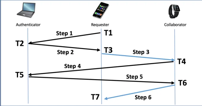
cryptographic functions” [37]. In this context, tokens must also be able to communicate with the server (i.e. they must be “smart” devices). In this implementation, each user will have two or more tokens, preferably devices s/he already owns (phone, laptop, watch, etc.) Before this embodiment of the co-authentication system can be used there is an initialization step which includes registering/device-pairing/associating all of the tokens with the authentication server so the server has a list for each user of all the user’s device names and each device’s public key. In this embodiment the communications between the tokens and between the tokens and the server will be encrypted so they each need to know each other’s public keys in line with public key cryptography. Figure 3.1 details the co-authentication protocol of this implementation.
Figure 3.1. Co-authentication Protocol. This shows the communication between the server and the tokens. The communications are labeled steps 1-6 and the time that each communication is initiated is labeled T1-T7.
15
In each step described in the following sections, the message (the request, the challenge or the session key) is bundled with the identification of the sender and a timestamp (to defend against replay attacks) and encrypted with the sender’s private key. The bundle is then signed with the recipient’s public key and sent. Other embodiments may have different configurations. The co-authentication protocol in this implementation is comprised of the following steps:
3.2.1 Step 1
One token associated with a user (the Requestor) sends an encrypted access request to the authentication server (the Authenticator). This request is signed with the Requestor’s private key and the bundle is encrypted with the Authenticator’s public key. In one embodiment of this protocol, the request is sent to the server via a wireless network.
3.2.2 Step 2
The Authenticator receives the encrypted message and decrypts it with its private key. The Authenticator uses the sending device’s name to retrieve a list of the device names and public keys of the sending device’s associated device(s) (these are known now as the
Collaborator(s)). The Authenticator generates a challenge (e.g. a nonce), bundles it, signs it with its private key and encrypts it with the Requestor’s public key and sends the challenge to the Requestor.
3.2.3 Step 3
The Requestor receives the encrypted challenge and decrypts it using its own private key. The Requestor re-bundles the challenge with its own device name and signs it using its own
16
private key and the public key of each of its associated devices (the Collaborator(s)). The Requestor sends the encrypted challenge on to one or more of the Collaborator(s). This can be done by any communications channel between the devices. Mr. Cetin and Mr. Subils did
extensive research successfully using Near Field Communication (NFC) and QR code/cell phone camera as a between-token communication channel. One of my tasks on this project was to implement a Bluetooth communication channel for this step (detailed below in section 3.4). There are many other creative and secure ways to communicate this information and this will be an area of further research.
3.2.4 Step 4
Each Collaborator receives and decrypts the challenge sent to it using its own private key. Each collaborator then signs the challenge with its private key and encrypts it with the Authenticator’s public key and send it back to the Authenticator as a challenge response. Public Key cryptography ensures that, without telling the secret, the Authenticator is assured that the recipients have been able to decrypt the secret and thus are present in the associated token group. Other embodiments might use a shared private key initially transmitted via an out-of-band channel or may use some other encryption mechanism.
3.2.5 Step 5
The Authenticator validation algorithm requires responses from a preset number of Collaborators. When a challenge request is received, the Authenticator stores the challenge request and waits for as many challenge responses as the validation algorithm requires. To do this the Authenticator runs the following validation algorithm:
17
1) take a current time measurement, subtract the time measurement taken at in step 2, above, when the original challenge was sent out. If the time elapsed is within a preset threshold go to the next step, else return an error message to the Requestor that the request is not authorized.
2) decrypt the message and store the sender’s device name and the timestamp.
3) check the message to see if it is valid, if valid go on to next step, else return an error message to the Requestor that the request is not authorized.
4) check the name of the device against the associated device list it received in the initiation step. If the device is listed go on to next step, else return an error message to the
Requestor that the request is not authorized.
5) check the security policy which defines the precise requirements to approve the authentication. The security policy may list all the user’s associated devices and the algorithm will require challenge responses from all but the Requestor. The security policy may be more expressive and allow approval, for example, if m-out-of-n devices are present or if certain required devices are present or according to some “weighting” of devices (giving some devices more “votes”), else return an error message to the
Requestor that the request is not authorized. 6) returns approve or not approve
7) if not approve then waits for another message from another Collaborator until a time limit causes it to drop out of the wait loop.
8) If the validation algorithm returns approval then the Authenticator creates a session key, bundles it with the Requestor’s public key and encrypts it with one (randomly chosen) of the Collaborators’ public keys, and sends it to that Collaborator, else returns an error
18
message to the Requestor that the request is not authorized.
3.2.6 Step 6
The Collaborator decrypts the encrypted message when it receives it from the Authenticator. The Collaborator signs the session key with its secret key, encrypts it with the Requestor’s public key and sends it to the Requestor by one of many possible communication channels. Part of my task was to write Android applications to transfer this message by Bluetooth (see section 3.4, below). The Requestor is now authorized and can now use the session key to access the resource it was originally requesting.
3.3 Advantages/Disadvantages of the Co-authentication System
Some of the benefits of many of the embodiments of the co-authentication system include that it is potentially quicker and easier to use than other authentication systems. One of the purposes of this usability testing is to prove this empirically. We believe that
co-authentication is just as secure as other systems and Mr. Cetin has performed formal ProVerif modeling to demonstrate this [15]. We believe this system is scalable due to the low user burden (also to be shown in usability testing). The system benefits from more expressive options defined in protocols such as 1) allowing access with subset of devices available, 2) certain devices can have differing weight/votes in access/no access decision, 3) system can allow situational exclusion, and 4) system can make the presence on the network of certain devices required.
There are, however, some areas that still need work including ease of initial set up overhead. There is also a need to mitigate the steal-in-place scenario when one of the devices is
19
compromised but still in the network so the network still works but the compromise is not
discovered by the user. Continuing intermittent network communication checks may be one way to uncover the theft.
3.4 New Bluetooth Token Communication Channel
Bluetooth is communication standard for a short wavelength (2.4 GHz band), short range (100 feet in version 2.0, 200 feet in version 4.0 and 800 feet in version 5) radio
communication protocol. It is optimized to work in a high interference environment by using a frequency-hopping spread spectrum technology. Bluetooth divides information into packets and pseudo-randomly transmits each packet on one of 79 channels (each having a bandwidth of 1 MHz) at approximately 800 hops per second for the “classic” Bluetooth implementation. Bluetooth has a master-slave structure with one master and up to seven slaves in a “piconet”. They all share one clock and two devices can communicate at any one time, with, for example, the master transmitting in even number time slots and receiving in odd, and vice-versa for the slave. A device can be in discoverable mode and transmit its connection information. A master can scan with an antenna to find discoverable (and not previously discovered) devices and, generally with user interaction, pair with those devices. Once bonded, the devices can
communicate via the radio frequencies listed above as long as they are both within range [16].
3.4.1 Co-authentication Collaboration
This embodiment of the co-authentication protocol is designed to have the flexibility to allow almost any form of secure communication between devices in the process of collaboration to the Authenticator. In their initial proof of concept, Mr. Cetin and Mr. Sublis implemented QR
20
and NFC communication functions between the devices [15, 38]. To extend this work I added Bluetooth functionality. To improve the developer usability, I also added comments and software “hooks” in the code to show future developers where to put future extensions of authentication functionality such as biometric authentication. I added comments in the android and server side code to label the timestamps (T1-T7) and Steps 1-6.
To implement Bluetooth functionality, I used Android libraries and also modeled Mr. Cetin’s Java code in Android Studio that he used to create QR and NFC communication functions. I created two new Bluetooth communication activities, created or linked all the supporting sub-functions and modified Mr. Cetin’s existing authentication server structure, detailed in steps 1-6, above, to allow the new activities to work.
3.4.2 Send Activity
I created a send activity. I added a Bluetooth option into the select activity menu. This function is called between step 2 and step 3, above, by the Requestor and the activity is step 3. This function uses Bluetooth Adapter and Bluetooth Service to get the challenge message from the Authenticator. It displays a layout activity while it is processing the incoming message.
I added a connection manager to look for other Bluetooth devices in range and manage all the connection details. This function then sends a small message to ensure connectivity and calls appropriate error handling if that is not the case. The function calls security manager from
connection manager to decrypt the challenge message using its own secret key. It gets it as a byte array and converts it into a string. At this time, for demonstration purposes, the code does not include the full encryption in step 3, above, and for testing the system is only currently set up for only one collaborator.
21 3.4.3 Scan Activity
I created a scan activity. This activity also sends out a small message to ensure connectivity and calls appropriate error handling if that is not the case. This activity listens for and accepts a Bluetooth radio signal by calling the Bluetooth connection function, and calls a message handler which receives and stores the incoming message.
22
CHAPTER 4
PROPOSED EMPIRICAL TESTING DESIGN
The co-authentication system is in early development and has not been integrated into any products at this time. Mr. Cetin and Mr. Sublis did initial proof-of-concept work including designing and implementing an authentication server and implementing between token
communication using QR codes/cellphone camera and NFC. Mr. Cetin did initial functional testing of two versions of the co-authentication system including approximating execution time, network usage, memory usage and battery consumption [15]. My thesis covers the next phase of initial usability testing which is limited empirical comparative testing between the
co-authentication system and outside co-authentication systems. The testing functionality and select data collection has been coded and is operational as further proof-of-concept work. The testing modules described in this thesis are not intended to be stand-alone and are intended to be
integrated into a larger testing construct preferably including realistic mock tasks for a user to do. Some authentication system usability researchers have created mock airport ticketing kiosks [17] and others have created a mock cellphone helpdesk forum [31], mock banking websites [31] and mock telephone banking formats [19]. The proposed tests in this thesis are visualized and described here as if they are stand-alone tests in a laboratory setting to detail the intended context and to highlight the maximal measurement capability but the full implementation of this usability testing is left for future work.
23
For the proposed preliminary comparative usability experiments my research team and I designed four independent testing modules. We chose the two baseline tests in order to compare our system to the most commonly used authentication solutions. It is important to the
experimental design to choose and accurately measure features of each authentication system that are statistically comparable to each other from system to system. We chose to record the time it takes test participants to complete comparable components of each authentication task. The users’ success rates are also important information and can be measured and added as future work. The experiments are numbered in this thesis for identification but in the actual testing they will be in random order for every test participant and will each be completed several times. Random order and repetitive testing of the same task has been suggested by many authors as a best practice to avoid the effects of learning bias [30]. The testing constructs are listed below in Table 4.1.
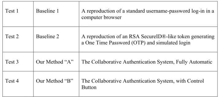
Table 4.1. Proposed Usability Experiments
Test 1 Baseline 1 A reproduction of a standard username-password log-in in a computer browser
Test 2 Baseline 2 A reproduction of an RSA SecureID®-like token generating a One Time Password (OTP) and simulated login
Test 3 Our Method “A” The Collaborative Authentication System, Fully Automatic Test 4 Our Method “B” The Collaborative Authentication System, with Control
24
WordPress is written in PHP and contains HTML, Perl and Javascript code intermixed. The login portion of WordPress is organized as a classic client-server. In this experiment the computer facing the TP acts as both the client and server because it is a login simulation. I made several modifications to WordPress Version 4.5.6.
I modified the CSS code in the client to make the user login screen visually match the login screen experiment specifications. In addition, after each type of testing each test
participant will be given a subjective questionnaire from which we can learn their preferences. We will also give them an opportunity to make suggestions for improvements. Throughout this thesis I refer to Test Administrators as TAs and Test Participants as TPs.
4.1 Test 1
The most commonly used computer user authentication system is a computer user typing a memorized username and password into a browser, the browser communicates securely with a server to compare the input to previously stored data and returns notice of access success or failure to the user. In order to use data from this type of system as an experimental baseline, my research team and I decided to reproduce a username-login system in a controlled
environment and obtain usability data from a test participant (TP)’s interaction with this system. One of my tasks was the software implementation of the TP-facing screens and the integrated data collection functionality.
4.1.1 Summary of Functionality
For this experiment I created a user interface and data collection system by making modifications to the well-known, stable, secure, open-source content management system
25
WordPress [44]. WordPress is designed to allow users to manage their own websites or blogs and offers templates and allows plug-ins to extend the functionality for website or blog customization. WordPress is generally installed on a server and acts as a network host. I isolated and used WordPress’s username-password login functionality and modified it to fit the experiment specifications defined by my research teammates. I traced and used the built-in WordPress encrypted communication functions. I also added the functionality of 1) collecting time data triggered by certain user inputs, 2) automatically performing calculations on this data, and 3) pushing the processed output to a server where I had created a data structure to hold it.
4.1.2 Experimental Set-up
As previously described, all four experiment modules are intended to be integrated into a larger testing construct with integrated user instructions, test functionality and data collection. Test 1 can be visualized to require a standard office desk and chair and a standard laptop or desktop computer with a standard display and keyboard. There will be a page of ten
“passwords” of increasing length and complexity on the desk or written on a nearby whiteboard, if available. All experiment instructions to the TPs, activities performed by the TPs and data collection will be done on the computer, no network connection is required for this experiment. No other equipment will be visible to the TP during this test.
4.1.3 Operation of Experiment
After greeting the TPs and after administering the short background questionnaire described previously, the TAs will instruct the TPs to follow the experiment instructions on the computer with no further priming. The first screen the TP sees will be will be a simple one page
26
instruction showing a sample login screen and instructing the TP to type in the passwords in the order they see them, one at a time, and showing a photo of the login screen with a large arrow pointing to the “submit” button. The instruction will tell them if they make a mistake before they hit the submit button they should backspace and correct it and if they type it in wrong and get a login failure message they should type that password in again until they are successful.
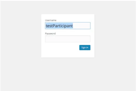
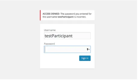
The TP will type in each password and get a success or failure page that is visible for 10 seconds. The screen will then go back to the login screen. Figure 4.1 shows the login screen. Figure 4.2 shows the screen after an incorrect password has been entered.
Figure 4.1. Test 1 Login Screen. Note that the username has been pre-filled by the system. All the user needs to do is type in the password.
27
Figure 4.2. Test 1 Error Message. This figure shows the error message that appears if the login is not successful.
After a TP types in ten passwords successfully, the computer will then display a standardized usability SUS [11,12]] questionnaire relating to the experience that the TP just had of typing in a password. The system will collect timing and accuracy information from the TPs actions and will also store the TP’s responses to the usability questionnaire. The TAs will later retrieve raw and calculated data and questionnaire responses from all the experiment TPs in one report for statistical analysis. The final page of the questionnaire will instruct the TP to wait for further instruction and will notify the TA to come start the next test.
4.1.4 Detail of the Code
The code modifications relate to changing the login screen’s appearance and the collection of data. These changes were made in HTML, Javascript and Perl.
28 4.1.4.1 Login Screen Appearance
1) I removed extraneous items on the login page, by commenting them out
2) I moved the location of the login and password prompts on the screen and changed their format
3) I filled in the username with a constant “TestParticipant” that will show on the screen so the only thing the user has to do is type in the password.
4) I moved the submit button’s location on the screen, changed its color and changed the wording on the button
4.1.4.2 Login Screen Data Collection
I made several changes to module “wp-login.php”. These include:
1) I modified the form in HTML in the client that is displayed in the user’s browser window 2) I embedded, in the HTML form, event listeners such as “on click” that would call a time
collection function when the user did specific things on the login form: such as navigate to the login screen, put his/her cursor in the password text box, end typing in the
password text box and click the submit button. 3) I created hidden fields in the form.
4) I captured the current time when this code is run (when the test starts), convert the time object into an integer (milliseconds since the epoch) and set the value in a hidden form field. The current development code displays this label and value (and each of the others) on the console for troubleshooting. I recommend this remain in the code until we need a “production” software version immediately before testing.
29
5) I created a Javascript event handler function that captures the time when the user places his/her cursor in the password box, converts the time object into an integer and set the value in a hidden form field.
6) I created a Javascript event handler function that captures the time when the user removes his/her cursor from the password box, converts the time object into an integer and set the value in a hidden form field. I also calculate the time difference between step 4 and 5 and step 5 and 6 and put these values into hidden form fields.
7) I created a Javascript event handler function that captures the time when the user clicks the submit button, converts the time object into an integer and set the value in a hidden form field.
8) I created a Javascript function that calculates the difference between collected times. In this way we obtain both the time the user actively types in the password and the total time s/he is on the login screen.
9) I created a new file on the server. I wrote the labels relating to the following data to the file: start time, time password started, time password stopped, amount of time to type in password, and time sign in clicked. I then retrieved and posted to newfile.txt the data that is in the corresponding variables. I used this data to calculate total log in time, created another label called “total log in time” and posted the label and the calculated data to the new file. Each time the user clicks the “submit” button, the client browser posts a line of data to the server and this is concatenated into the newfile.txt file. The experimental design calls for the accumulation of data in the newfile.txt file during the administration of the experiment and at the end of the experiment retrieval of the data in a block by the researchers for analysis. This format is intended to preserve the integrity
30
and metadata of the original data and minimize the possibility of inadvertent or intentional data modification.
4.2 Test 2
Another well-known authentication system that we chose to use as a baseline for our usability testing is the RSA SecurID ® system [32]. This is a hardware token such as a key fob which is manufactured with a preset “seed” random key and a built-in clock and is pre-registered to a particular username on an authentication server. The token generates and displays a series of one time passwords (OTPs) at fixed time intervals using a cryptographic algorithm. The user views the display on the token at that moment and manually copies the values displayed on the token into a login display using the keyboard of the device for which s/he is requesting
authentication. The authentication server where the token is registered has a database of usernames, the corresponding seed values of their tokens, and also has a synchronized clock. When the user enters the value s/he sees at that moment on the token, the server uses its own time value to calculate, based on the username and his/her original seed value, what value should be displayed on at user’s token at that time. If these user-entered values and the stored values match, authentication is successful. The RSA SecurID ® is generally used as a second factor in a two-factor authentication.
4.2.1 Summary of Functionality
The RSA SecurID ® system can be securely emulated in software (a soft token). Two independent computer systems with synchronized clocks using a shared secret key or using public key cryptography can provide authenticated access to each other in the same manner as
31
the hardware token system described above. We chose to use a soft token for our baseline testing.
4.2.2 Experimental Setup
As previously described, all four experiment modules are intended to be integrated into a larger testing construct with integrated user instructions, test functionality and data collection. Test 2 is visualized to require a standard office desk and chair, two cell phones and standard laptop or desktop computer with a standard display and keyboard. The computer needs to be connected to a network with WiFi communication capability and will act as an authentication server and will also display the experiment instructions and questionnaire to the TP. In its role as a server, the computer will collect the test data . For our experimental setup I chose to use two Android LG Tribute 2 cell phones. These phones have the LTE Qualcomm Snapdragon 1.2 GHz quad-core processor, 1 GB of RAM, 8 GB of expandable storage space, a 4.5 inch IPS screen with 480x854 pixels, a 1900 mAh battery, a 5 MP rear camera and a 1.3 MP front facing camera. These phones are not connected to a telephone or internet service provider’s network but are used here as independent computing devices and connect only to the WiFi network as
specifically instructed within the experiment. This experiment requires that the two phones are placed on the desk immediately in front of the TP and in front of the display so there needs to be room for this on the desk surface.
One phone runs the OTP generator application and the other runs the OTP login application. Before the experiment is run, the phone running the OTP generator application is registered with the authentication server in order to share a secret key (seed). This phone is disconnected from the server and then independently simulates an RSA SecurID ® token by
32
generating a series of OTPs at fixed time intervals. The phone that runs the OTP login application simulates a login. The authentication server has a database of key seeds from
registered devices and a synchronized clock that it uses to calculate the expected current value of the key. The login phone is connected to the authentication server via WiFi.
4.2.3 Operation of Experiment
The test administrator (TA) will turn both phones on and open the “OTPgenerator” application on one phone and place it on the desk to the left of the TP. The TA will open the “OTPlogin” application on the other and place that phone on the desk to the right of the TP. The OTP generator phone will display a “start experiment” button, the OTP Login will display the login screen. A photo of the OTP login screen is shown in Figure 4.3.
33
The TA will instruct the TP to follow the instructions on the computer and will demonstrate navigating (i.e. swiping or mousing) on the computer to get to the next page.
The computer will display simple experiment instructions with photos of the two phones. The instructions will tell the TP that s/he has to enter the code s/he sees on the left phone into the login screen on the right phone and the code on the left phone will be visible for only 10 seconds. If s/he is not able to enter the code in that time a new code will be generated and s/he should try to type in the new code. S/he should continue until s/he receives a message that s/he has successfully completed 10 logins.
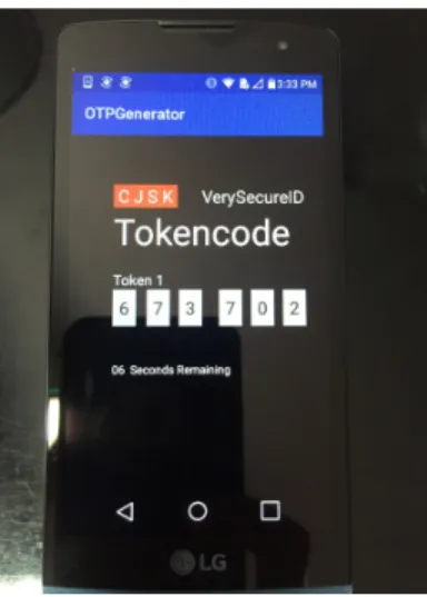
The TP will read through the instructions and then, when s/he is ready, the TP will open the application on both phones to start experiment. The left phone will display the simulated RSA SecurID ®screen with blank six digit number and a blank count down timer. The phone will have a first screen with a “generate code” button (not yet implemented). The TP will select the button “generate code” on the left phone and it will display a 6 digit number. A photo of the simulated RSA SecureID(R) is shown in Figure 4.4.
Figure 4.4. Test 2 Showing OTP Generation. This is a photo of the simulated RSA SecureID ® screen with a random key displayed.
34
The TP will touch the “type otp here” input box on the right phone and a keyboard will pop up. The TP will type in the OTP s/he sees displayed on the first phone into the simulated login display on the second phone. The second phone sends the input to the authentication server. At this time this input is not encrypted but as future work this communication should be added to this communication. The authentication server calculates the expected current value of the key, compares the expected current value to the input and returns a result (match or not match) value to the simulated login phone. The login phone will display a login success or failure message to the TP. The server also measures the start time and stop time at various points of the soft token authentication process, measures the number of successful and total tries at authentication and stores this data and the calculated elapsed times in a file for the researchers to use in their usability analysis. When the TP has successfully logged in 10 times the right phone will display an “experiment is complete” message.
4.2.4 Detail of Code
The code that obtains the data in this experiment is designed as follows: This system has a two client and one server configuration. My colleague, Cagri Cetin designed and built an authentication server for the original demonstration of this system. For my contribution to this project I modified his authentication server to incorporate the simulated RSA SecurID ®. I added the following functionality to the server code 1) store the OTP, 2) check the OTP against input, and 3) capture the timing of various user actions. The authentication server was written in Java SE-1.6 using Spring Tool Set (STS), an Eclipse based development environment, so I also used this system for the modifications.
35 4.2.4.1 Login Screen Appearance
I created two original Android applications for the two clients, which I wrote in
Android Studio Version 2.1.2. The first client is “OTPgenerator” which contains a Java function and associated sub-functions and display functionality. In this function the following actions occur:
1) start a 10 second count down timer,
2) calculate and display the number of seconds remaining,
3) generate a 32-bit secret using the Java library function generatebase32secret which outputs a string,
4) take the first 6 characters in the string and output them to text view, 5) end the string to the authentication server (for matching), and 6) reset the countdown timer.
The function calls the display functions. I also designed a layout which is stored in the program resources file. This is an HTML layout of the image to be seen by the user and is intended to mimic the RSA SecurID ®’s appearance by displaying the six digits and the number of seconds remaining that these digits will be displayed.
The second client is “OTPLogin” which is another Java function and associated sub-functions and display functionality. In this function the following actions occur:
1) outputs a layout for user input,
2) “listens” for input and puts onclicklistener inputs into variables, 3) ends the variables to the authentication server (for matching), 4) receives notice if a match has occurred or not
36
of the result (it may also call a media player function because the success message is animated). The function calls the display functions. I also created an .xml layout and drawables for the OTPlogin and stored them in resources.
4.2.4.2 Data Collection
I include time capture functionality for experiment measurements in the OTPlogin application and in the server code. In the OTPlogin application I add code in the login function to record the time when the screen is first opened, the time when the user’s cursor is placed in the “Type OTP here” data entry box (I use the onFocusChangeListener function which calls
onFocusChange), and the time when the user clicks the “Verify OTP” button. The
onFocusChange function only takes one timestamp regardless of how many digits are typed in. Every digit the user types runs the function but data is only collected on the first one. The success or failure information is collected on the server side. These three times are converted from data time objects into long integers and sent to the server by a function which concatenates the numbers onto the URL when it sends the number that the user typed in. The variables are then cleared.
On the server side, in the CheckOTP function in the HomeController, I bring in the time capture data from the URL and put it into variables. I then put it into a log named “Test 2 data” that is accessible in debug mode. As future work we can create an output structure and report format to output this data for analysis.
37 4.3 Test 3
In Tests 3 and 4 we are testing the usability of the co-authentication system for comparison with the two baselines examined in tests 1 and 2. For the purposes of testing our Collaborative authentication system against the baselines illustrated in Test 1 and Test 2, above, I chose to use the new Bluetooth version as our testing model. For the purposes of testing I
assume that the initial pairing of the user’s devices has already been done and that is not part of present usability testing. This mirrors actual usage and is a reasonable assumption.
4.3.1 Summary of Functionality
The functionality of the Bluetooth code is described in detail above, in section 3.2. The functionality of the usability testing components is to measure the overall amount of time that the authentication process takes using the co-authentication system. I created variables in the
Android app to capture timing information at the Android device and send it to the server when the experiment is complete.
4.3.2 Experimental Setup
As previously described, all four experiment modules are intended to be integrated into a larger testing construct with integrated user instructions, test functionality and data collection. Test 3 and 4 are visualized to require a standard office desk and chair, two cell phones and standard laptop or desktop computer with a standard display and keyboard. The computer needs to be connected to a network with WiFi communication capability and will act as an
authentication server and will also display the experiment instructions and questionnaire to the TP. In its role as a server, the computer will collect the test data. For our experimental setup I
38
chose to use the same two Android LG Tribute 2 cell phones I used in Experiment 2. The cell phones have new Bluetooth communication applications downloaded and resident on the phones. The phones communicate with each other via Bluetooth and with the server via WiFi.
4.3.3 Operation of Experiment
Tests 3 and 4 are essentially the same test with one small difference: in one test (named A for automatic) the authentication protocol starts as soon as registered devices are connected to the authentication server, in the other test (named B for button), the authentication protocol requires that devices ask the user for permission to complete the authentication process (such permission is given by the user pressing a button on the requesting device). The two phones will sit on the desk in front of the TP. The test instructions will show the TP how to open the
application on both phones and how to touch the start experiment button. In Test 3, the automatic version, the TP opens the “3A” application on both phones. There is no user input required and one phone will display authentication success or failure when it the authentication process is done. If the other phone is not on and nearby and the application is not open on this phone, authentication will not occur. The timing information is collected on the testing device invisibly to the TP and is sent to the server at the completion of the experiment where it is retrieved by the TAs for analysis.
4.3.4 Detail of Code
The detail of the new Bluetooth functionality is described in section 3.4, above. To create testing capability I adding the following code:
39
2) I created a function to send this time stamp to the server.
3) I added a time stamp in the handleMessage function in the controlIfChallengeDone function in BluetoothScanActivity.
4) I added another function also to send this time stamp to the server. 5) I added code to the server by adding a function receiveBTStartTime in the
HomeController to retrieve the two time stamps.
4.4 Test 4
Test 4 is identical to Test 3 but with the addition of one button displayed to the user which, when pressed, starts the authentication process that automatically works in the Test 3 version.
4.4.1 Code for the Button Function
The button functionality is in the challenge success activity called by the scan activity. It is a simple layout with the text “Approve Access” and onclick calls the success message function. The primary reason for this button is to alert the user that a new device is requesting access. If the user discovers one of his/her devices is stolen s/he can decline to press the approve access button and prevent the new device from having access.
4.4.2 Operational Differences from Test 3
The two phones will sit on the desk in front of the TP. The test instructions will show the TP how to open the application on both phones and how to touch the start experiment button. In Test 4, the button version, the TP opens the “3B” application on both phones. One phone will
40
display a button asking if the user requests authentication. The user touches this button to run the authentication process. This phone will display authentication success or failure when it the authentication process is done. If the other phone is not on and nearby and the application is not open on this phone, authentication will not occur. The timing information is collected on the testing device invisibly to the TP and is sent to the server at the completion of the experiment where it is retrieved by the TAs for analysis.
41
CHAPTER 5
CONCLUSION AND FUTURE WORK
This thesis describes authentication, usability testing and one embodiment of the co-authentication system to provide context for future usability testing of the co-co-authentication system. In this thesis I also describe the new work done to develop and implement an extension of the co-authentication system to add a Bluetooth communication capability between tokens. For the benefit of future co-authentication system development I have tried to modularize all functional aspects and include hooks in the form of comments in the code for adding future token communication capabilities such as biometrics. I hope that the description of adding the
Bluetooth capability in this thesis may serve as a roadmap for future developers adding other communication capabilities.
This thesis also details the development and implementation of four new usability test modules. Two of these simulate existing well-known authentication systems – the
username/password login in a browser and the hardware token one time password (OTP). This thesis describes the addition of embedded usability (time to complete task) measurements. The other two usability test modules embed usability (time to complete task) measurements. All four test modules collect timing information taken in places in the respective codes that I believe are functionally comparable from application to application. Obviously experimentation results may inform this placement and the tests are presented here to highlight where future tuning may occur. The user’s success rates are also important information and should be included in future
42
work. Tests 1 and 2 output fairly well formatted data but in Tests 3 and 4, at this time, the data is available in the debug mode. The data is all clearly separated by test number and I leave the integration of the tests and statistical analysis tools for future work. I also leave the design of usability mock-up models that will present TPs with realistic tasks to others.
The Co-authentication system has many possible embodiments and versions and I have chosen just one to use for demonstration and proof of concept of usability testing. I hope I have illustrated why usability testing is valuable to the design process in general and provided a useful framework of some possible usability tests.