Fang: A Firewall Analysis Engine
Alain Mayer
yAvishai Wool
zElisha Ziskind
xAbstract
Today, even a moderately sized corporate intranet con-tains multiple firewalls and routers, which are all used to enforce various aspects of the global corporate security pol-icy. Configuring these devices to work in unison is difficult, especially if they are made by different vendors. Even test-ing or reverse-engineertest-ing an existtest-ing configuration (say, when a new security administrator takes over) is hard. Fire-wall configuration files are written in low-level formalisms, whose readability is comparable to assembly code, and the global policy is spread over all the firewalls that are in-volved.
To alleviate some of these difficulties, we designed and implemented a novel firewall analysis tool. Our software al-lows the administrator to easily discover and test the global firewall policy (either a deployed policy or a planned one). Our tool uses a minimal description of the network topol-ogy, and directly parses the various vendor-specific low-level configuration files. It interacts with the user through a query-and-answer session, which is conducted at a much higher level of abstraction. A typical question our tool can answer is “from which machines can our DMZ be reached, and with which services?”. Thus, our tool complements ex-isting vulnerability analysis tools, as it can be used before a policy is actually deployed, it operates on a more under-standable level of abstraction, and it deals with all the fire-walls at once.
1
Introduction
1.1 MotivationFirewalls are the cornerstones of securing a corporate in-tranet. Once a firewall is acquired, a security/systems ad-ministrator has to configure and manage it to realize an ap-propriate security policy for the particular needs of the
Bell Laboratories, Lucent Technologies, Murray Hill, New Jersey 07974, USA. y E-mail:[email protected]. z E-mail:[email protected]. x E-mail:[email protected].
pany. This is a crucial task; quoting from [17]: “The sin-gle most important factor of your firewall’s security is how you configure it”. However, while firewalls themselves have seen some impressive technological advances (e.g., stateful inspection, transparency, performance, etc), firewall config-uration and management seem to be lagging behind.
Even understanding the deployed firewall packet-filtering policy can be a daunting task. Administrators to-day have no easy way of answering questions such as “can Itelnetfrom here to there today?”, or “from which ma-chines can our DMZ be reached, and with which services?”, or “what will be the effect adding this rule on this fire-wall?”. These are basic questions that administrators need to answer regularly in order to perform their jobs, and some-times more importantly, in order to explain the policy and its consequences to their management. There are several rea-sons why this task is difficult: (i) Packets may have multiple paths from source to destination, each path crossing several filtering devices. To answer a query the administrator would need to check the rules on all of these. (ii) Typical vendor configuration tools deal with a single device at a time, which may lead to inconsistent global behavior. If packet-filtering devices made by different vendors are involved, the situa-tion quickly becomes much worse. (iii) Even understand-ing the policy on a sunderstand-ingle interface of a sunderstand-ingle packet filter-ing device is problematic: Firewall configuration languages tend to be arcane, very low level, sensitive to rule order, and highly vendor specific.
Consequently, we believe that security configuration analysis, and in particular firewall policy analysis, is an im-portant component in the process of administrating the se-curity of a corporate intranet. The research described in this paper is a first step towards the creation of new tools that adequately support firewall policy analysis.
1.2 Related Work
There are many firewall products on the market, from vendors such as CheckPoint [4], Cisco [14, 10], Sun Mi-crosystems [19], Lucent Technologies [12], and Network Associates, just to mention a few. (See [9] for an updated list of vendors). Additionally, there are many books on firewall technology and on how to build your own firewall
(e.g., [5, 3]). A recent treatment can be found in [1]. While most of the firewall offerings include configuration tools with varying degrees of sophistication, none of these ven-dors seems to focus on firewall and security policy analysis tools.
Note that the issue of testing a firewall product (see, e.g., [16]) is different from our goals. We assume that all deployed filtering devices work properly and we are inter-ested in testing the configuration of these devices.
Currently there are a number of vulnerability testing tools available. For instance, Satan [7, 8] is software that attempts to exploit known flaws in widely deployed proto-cols and operating systems, some of which can be blocked by appropriate firewall policies. So, in particular, Satan can be used to test the firewall policy. One can also purchase a dedicated hardware box that connects to the intranet (e.g., NetSonar [13]) and probes the network, thereby testing the deployed routing and firewall policies.
We emphasize that these tools are active: they send and receive packets on the network. As such, they suffer from several restrictions:
If the intranet is large, with many thousands of ma-chines, these tools are either slow (if they test every single IP address against every possible port), or statis-tical (if they do random testing). Certainly, they cannot test every possible IP address on the Internet. In fact, currently NetSonar’s scan list has a limit of 2500 hosts. Vulnerability testing tools can only catch one type of firewall configuration error: allowing unauthorized packets through. They do not catch the second type of error: inadvertently blocking authorized packets. This second type of error is typically detected by a “deploy and wait for complaints” strategy, which is disruptive to the network users and may cut off critical business applications.
Active testing is always after-the-fact. Detecting a problem after the new policy has been deployed is dan-gerous (the network is vulnerable until the problem is detected and a safe policy is deployed), costly (deploy-ing policy in a large network is a time consum(deploy-ing and error prone job), and disruptive to users. Having the ability to cold-test the policy before deploying it is a big improvement.
An active vulnerability tool sends packets, and detects problems by examining the return packets it gets or doesn’t get. Therefore, it is inherently unable to test network’s vulnerability to spoofing attacks: If the tool spoofs the source IP address on the packets it sends, it will never receive any return packets, and will have no indication whether the spoofed packets reach their destination or not.
An active tool can only test from its physical location in the network topology. A problem that is specific to a path through the network that does not involve the host on which the active tool is running will go undetected. 1.3 Contributions
In this paper we present a novel software-only firewall policy analysis tool, which has the following design goals.
Use an adequate level of abstraction: The administra-tor should be able to interact with the tool on an ad-equate level of abstraction, i.e., on the same level at which the corporate security policy is defined or ex-pressed. In a large network, the tool should allow to quickly focus on important security aspects of testing. Do no harm: Policy analysis should be possible with-out having to change or tinker with actual network con-figurations, which in turn might make the network vul-nerable to attacks.
Be passive: Policy analysis should not involve sending packets, and should complement the capabilities of ex-isting active test tools.
Be up-to-date: The analysis should accurately reflect the policy which is actually deployed (or is about to be deployed), and not an out-of-date description of it. Be efficient: The time required to perform common
tests should not depend on the number of machines in the network (or on the Internet). It should only depend on the complexity of the topology, and on the number of rules in the various rule-bases.
Be easy to use: The interactive user interface should al-low the tests to be performed with a few mouse-clicks. To meet these goals, we designed and implemented “Fang” (for Firewall ANalysis enGine). Fang collects and reads all the relevant configuration files, and builds an inter-nal representation of the implied policy and network topol-ogy. It provides a graphical user interface for posing simple queries of the form “does the policy allow service sfrom atob?”, or aggregate queries wheresmay be a set of ser-vices (up to a wildcard “all possible serser-vices”), andaand b may be arbitrary sets of IP addresses (up to a wildcard “all possible addresses”). Given a query, Fang simulates the behavior of the various firewalls, taking into account the network’s topology, and computes which portions of the original query would manage to reach from source to des-tination: Perhaps only a subset of the services are allowed, and only between subsets of the specified source and des-tination host-groups. Fang has the capability of simulat-ing spoofsimulat-ing attacks: It allows its user to specify where the
packets are to be injected into the network—which may be not the true location of the source host-group. Fang can also take into account firewall rules that perform network-address-translation (NAT).
The software was developed as a module in the Firmato firewall management toolkit [2], and makes use of some of its modeling techniques. However, it can be used indepen-dently of the other components in the toolkit.
We believe our design goals offer advantages and capa-bilities currently not found in any tool and complement the existing tools.
Organization: In the next Section 2 we discuss the
compo-nents on firewall policies, and introduce some terminology. In Section 3 we give some details of the inner workings of Fang: internal model, algorithms, data structures, GUI, etc. We then walk the reader through a complete realistic example of using Fang in Section 4. We mention possible extensions in Section 5, and we conclude with Section 6.
2
Background and Terminology
2.1 The Components of a Firewall Policy
A firewall is typically placed on a gateway, separating the corporate intranet from the public Internet. This gateway may be either a dedicated machine or a router. Most of to-day’s firewalls are configurated via a rule-base. In the case of a firewall guarding a single, homogeneous intranet (e.g., a small company LAN), a single rule-base instructs the fire-wall which inbound sessions (packets) to let pass and which to block. Similarly, the rule-base specifies which outbound sessions are allowed. The administrator needs to implement the high-level corporate security policy using this low-level rule-base.
A medium- or large-sized company, and any company which has an e-commerce web presence, usually has more than a single firewall; its firewalls divide the company’s in-tranets into multiple zones, such as the demilitarized-zone (DMZ), corporate net, human resources, etc. In this case, the security policy is typically realized by multiple rule-bases, located on the various gateways that connect the dif-ferent zones to each other. Thus, the interplay between these rule-bases determines which sessions will be allowed through.
A typical firewall’s configuration tool allows the secu-rity administrator to define various host-groups (collections of IP addresses) and service-groups (groups of protocols and corresponding port-numbers at the hosts which form the endpoints). A single rule typically includes a source, a destination, a service-group, and an appropriate action. The source and destination are host-groups, and the action is ei-ther “pass” or “drop” (the packets of the corresponding
ses-sion).1 In many firewalls, the rule-base is order-sensitive: The firewall checks if the first rule in the rule-base applies to a new session. If so, the packets are either dropped or let through according to the action of the first rule. Otherwise, the firewall checks if the second rule applies, and so forth. 2.2 Terminology
Firewall terminology varies slightly from vendor to ven-dor, so we need to precisely define the terms we use.
Gateways: These are the packet filtering devices.
Gate-ways can be either firewalls or routers.
Interfaces: Typically, a gateway has multiple network
con-nections. Each connection goes through an interface. We assume that each interface has a packet filtering rule-base associated with it (this is more general than assuming only a single rule-base per gateway). Nor-mally a gateway is multi-homed (see [18]), and each interface has its own unique IP address. However, this is not the case when the gateway operates as a bridge [11].
Zones: The gateways partition the IP address space into
disjoint zones. Precisely, a zone z is a maximal set of IP addresses such that packets sent between any two addresses in z do not pass through any filtering gateway. Most zones correspond to a corporation’s subnet(s), usually with one big “Internet” zone corre-sponding to the portion of the IP address space that is not used by the corporation.
Service: This is the combination of a protocol-base (e.g., tcp, udp, etc.) and the port numbers on both the source and destination sides. For instance, the service
telnet is defined astcp with destination port 23 and any source port. A service-group is simply a set of services.
Hosts A host is specified by a single IP address. A
host-group is a set of IP address (or IP address ranges).
3
Fang Under the Hood
3.1 Basic Dataflow in Fang
Before Fang can be used, it needs to have an instantiated model of the network’s topology. So the first thing a Fang user needs to do is to write a topology description file. The language we use to describe the topology is a subset of Fir-mato’s MDL language. A complete example of a topology
1Other actions are usually allowed, such as writing a log record or
per-forming network-address-translation (NAT). We focus only on the basic pass/drop actions, for sake of brevity.
Query
Analyzer Program
User (MDL Program) Topology Definition
(e.g, Lucent Firewall)
Answer Configuration File
(e.g, Cisco Router IOS)
Configuration File
Configuration File (e.g, Cisco Router IOS)
Figure 1. Fang’s data flow.
file appears in Section 4, and we refer the reader to [2] for more details.
Note that we use the term “topology” somewhat loosely. Fang does not need to be aware of every router and switch in the network, and is indifferent to the routing scheme that is used. We only care about devices that have packet filter-ing rule-bases installed on them, and about the zones these devices define. At this level of granularity, we believe the topology is quite stable; The topology file only needs to be touched if firewalls are added or replaced in the network. Mundane events like a change in routing or adding a new network device would not invalidate the existing topology file. Thus, we expect that writing or updating the topology file is a rare event.
Once the topology file is written, Fang’s GUI may be launched. The topology file is then opened and parsed, which populates the internal data structures with the topol-ogy information (see Figure 1 for a sketch of the data flow). As part of the topology file, the user specifies the names of the firewall configuration files that contain the rule-bases for all the gateway interfaces. After reading the topology file, Fang parses each of these configuration files in turn (us-ing a separate “front-end” module for each supported brand of firewall), and populates its internal rule-base data struc-tures for each device. Note that these configuration files are vendor-specific, and are created by whatever tools are used to configure the devices in question.
After all the files have been parsed, Fang creates its drop-down menus, and is ready to accept user queries.
3.2 The Internal Model
3.2.1 Topology
The network topology is modeled as follows: the network is partitioned into Zones, which are connected through Gate-ways. A Gateway has an Interface for each adjacent Zone. Each Interface either has its own IP address (and is consid-ered a Host for some purposes), or is declared to be invisi-ble (using theINVISkeyword) if the firewall operates as a bridge. Packets leaving and entering a Zone can be filtered by the Gateway on the corresponding Interface; packets sent and received within the same Zone cannot, simply because they do not pass through any Gateway. Therefore, from the Fang’s perspective, there exists a path between any two hosts in the same Zone; any and all filtering is performed by the Interfaces. Zones consist of host-groups. Host-groups are typically further subdivided into a hierarchy of smaller host-groups or single hosts.
3.2.2 Naming
In our model, all the objects (hosts, host-groups, service-groups) have names. This allows us to have a high level of abstraction when interacting with the user: Meaning-ful names are more expressive than raw IP addresses and port numbers. To the extent possible, Fang obtains these names from the vendor-specific configuration files.2 How-ever, since each device and interface is assumed to have been configured independently, there may be name con-flicts. For instance, the administrator may have defined the name http to signify tcp on port 80 on one gateway, while on another gateway she may use the same name to meantcp on ports 80, 8000, and 8080. To support this level of naming, Fang maintains a separate symbol table context per interface (i.e., per rule-base). If the same name appears in different contexts with different meanings, Fang will show all the variants in its drop-down menus, prefixed with the interface name. Otherwise, if all the variants are identical, the name will appear only once with no prefix.
3.2.3 Rule-bases
The implicit security policy in place within the corporate network is derived from the (vendor specific) firewall/filter rule-base files. Fang transforms each of these files, asso-ciated with an Interface, into a table of logical rules con-taining the following record structure (simplified for ease of explanation):
struct rule {
struct hostgrp *source;
2Some vendor products, notably Cisco’s IOS and PIX, do not provide
struct hostgrp *dest;
struct servicegrp *service_grp;
direction_ty direction;
action_ty action;
};
The actual semantics differ among different vendors. To illustrate the concept we explain the above with an exem-plary semantics: When packets are filtered, the rules in the list are examined in their order until a match occurs. The
source,destandservice grpfields are compared to the corresponding fields in the packet. The direction speci-fies whether the rule applies to packets entering (IN) or leav-ing (OUT) the gateway on which this interface sits (i.e., the rules are gateway-centric). The wildcard direction (BOTH) indicates that the rule applies to both directions. If a match occurs, the corresponding action (DROP or PASS) is per-formed.
The internal rule-base table also supports rules that per-form NAT, and hence, therulestructure has some addi-tional fields. We omit the details.
3.2.4 Queries
A central object in Fang is a query. A query is a triple, consisting of a source host-group, a destination host-group, and a service group. The semantics of such a query are “which IP addresses within the source host-group can send services from the service-group to which IP addresses in the destination host-group?”. This is described by the following data structure:
struct query {
struct hostgrp *src; struct hostgrp *dst;
struct servicegrp *service; };
Recall that host-groups and service-groups may be wildcards, i.e., any element of the query triple can be the “*”-wildcard, meaning “any”. So the ques-tion “which machines can use the company’s web-servers?” can be expressed by the query triple like (*, web servers, http services), assum-ing that the host-group web servers and the service-grouphttp servicesare defined.
It is usually the case that not all the (packets described by a) query can reach the destination. Through the operations of the various rule-bases, some packets may be dropped. Therefore, Fang’s answer to such a query is a refined list of “sub-queries”, i.e., a list of query triples where each element is a subset of the corresponding element in the query triple.3
3The answer “triples” actually contain a few additional fields that deal
with NAT. We omit the details.
The semantics of the answer are that for each subset triple, the corresponding source host-group can indeed send the service to the destination host-group.
3.2.5 The Gateway-Zone Graph
Fang’s query engine, described in the next section, is based on a graph algorithm, where the graph is defined by the topology. For this purpose, the internal model contains the following auxiliary graph.
Definition 3.1 Let the gateway-zone graph be a bi-partite
graphH =((G[Z);I)whose vertices consist of the set of gatewaysGand the set of zonesZ. The set of interfacesI forms the edges:Hcontains an edgei=(g;z)connecting a gatewayg 2 Gto a zonez 2 Z iffg has an interfacei whose adjacent-zone isz.
The vertices of the gateway-zone graph are implemented using the following structure:
struct node { union { struct zone *z; struct gateway *gw; } zg; struct hostgrp *hg; node_ty type; struct query *q; };
There is anodefor each gateway and zone. Thetype
field indicates which one is represented by that node. The
hgfield keeps the IP range contained in the node. For zone nodes, hgis the host-group of the zone minus the IP ad-dresses of the interfaces adjacent to this zone; for gateway nodes, it is the set of IP addresses of the interfaces attached to the gateway. Theq field in the node struct is used for processing the query, as will be explained shortly.
3.3 Fang’s Query Engine Algorithm
The core of Fang’s query engine is a combination of a graph algorithm and a rule-base simulator. It takes as input a user query consisting of a source and destination (both of which are host-groups) and a service group. It then simu-lates the behavior of all the packets described by the query as they traverse the network.
Initially, the user’s query is attached to the node in the gateway-zone graph which contains the source host-group.4 Then, the algorithm attempts to propagate the query over all
4If the source host-group is not contained in a single zone (e.g., when
the wildcard, *, is used), the source host-group is broken up into disjoint host-groups, each of which is contained in a zone. A separate graph search is performed for each host-group.
the edges that connect the current node. It then continues in the same manner, propagating the query further until it searches the entire graph.
The basic step of the algorithm is propagating a query over an edge in the gateway-zone graph, which represents a firewall interface. This models the effect of the rule-base that is attached to the interface on the packets described by the query. Typically, only portions of the query can cross any given edge, since some of the packets would be dropped by the interface. Therefore, after crossing an edge, the query may need to be broken up into a set of more re-fined queries, that represent only those packets that would have been allowed through. For instance, the original query may have been (corporate net, internet, *), but the rule-base only allows outgoing http andsmtp, so the set of queries that reaches the other side of the edge is now(corporate net, internet, tcp), (corporate net, internet, smtp).
Note that some nodes may be visited more than once, while other will not be visited at all. This is because the algorithm backtracks over all possible paths the query can take through the network, and continues as long as some portion of the query remains un-dropped. If the query can reach a nodev(whether a zone or a gateway) via different paths, the new query that is attached tovis the union of the query results reachingvon each of the possible paths. The search is slightly optimized to not perform a traversal if it is clear that no new packets will be allowed through that have not been already by other paths.
The final stage in processing a query is to collect the re-sults. This simply involves looking at the node or nodes that contain the destination host-group and picking out those queries that have reached their correct destination.
In the worst case, the complexity of the algorithm is ex-ponential in the size of the gateway-zone graph. However, this worst case can only occur in very dense graphs. Typi-cal gateway-zone graphs are very sparse, since firewalls are normally placed at strategic choke points in the network, and the most common case gateway-zone graph topology is a tree. On a tree topology the algorithm is essentially a depth-first-search, i.e., it is linear in the size of the graph. Furthermore, since we only model zones that are separated by firewalls, gateway-zone graphs tend to be quite small. 3.4 Spoofing
A small extension to the basic algorithm allows testing for spoofing attacks. In addition to the source, destination and service parameters that define a query, we add an op-tional fourth parameter which specifies the true source from which the packets originate. When this fourth parameter is defined, the original source host-group is then understood to be the fake source address in the packet. Processing such
a query is identical to that described above, expect that in-stead of starting from the nodes that contain the fake source host-group, the algorithm starts at those nodes that contain the true source.
3.5 Fang’s User Interface
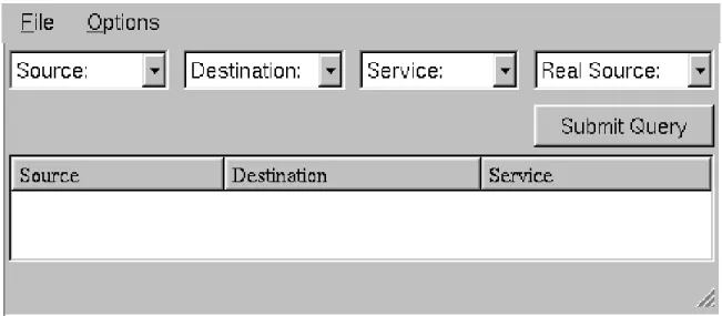
Fang has a graphical user interface (GUI) which was de-veloped using Qt [15, 6], a C++ class library for writing portable GUI applications (see Figure 2).
After launching Fang the user needs to read in the MDL topology file (viaFile!Openmenu). This in turn tells Fang where the device configuration files of each fire-wall/filter device can be found. Fang then collects this in-formation and populates its internal model. It is then ready for the query/answer session.
The user forms a query by choosing each element of the query triple from a drop-down menu offering the choice of all the host-groups or service-groups that were defined in the configuration files. After clicking on the Submit button, the answer is presented as a list of triples in the box below. Each result triple can be expanded to offer more detailed information via clicking on the[+]icon.
Figure 2 shows the GUI with the spoofing option turned on. When the option is turned off, the right-most drop-down menu disappears.
4
A Complete Example
The quickest way to get an idea of the usefulness of Fang is with a real-world example, which we give in this section. 4.1 The Topology
The example describes a topology for an imaginary (yet realistic) corporation with a two-firewall network configu-ration, as shown in Figure 3.
The external firewall guards the corporation’s Inter-net connection. Behind it is the DMZ, which contains the corporation’s externally visible servers which provide
http/https,ftp,smtp(email) anddnsservices. Two distinct machines provide these services, one only provid-ing thednsservice, and the other providing the rest.
Behind the DMZ is the internal firewall, which guards the corporation’s intranet. This firewall has three interfaces: one for the DMZ, one for the corporate network zone, and a separate interface connecting to the firewall administration host.
Within the corporate network zone, there is one distin-guished machine, “control”, which provides the administra-tion for the servers in the DMZ.
Figure 2. GUI for Fang.
111.222.3.*
Firewall Administration Zone
Corporate Zone 111.222.2.* Demilitarized Zone (DMZ) 111.222.1.* 000 000 000 111 111 111 0000 0000 0000 0000 0000 0000 1111 1111 1111 1111 1111 1111 00 00 11 11 00 00 11 11 000 000 000 111 111 111 000 000 000 111 111 111 0000 0000 0000 0000 0000 0000 1111 1111 1111 1111 1111 1111 Internet I_dmz_corp I_internet_dmz I_corp_in I_admin I_dmz_in multi_server dns_server control fw_admin
4.2 The Security Policy
The policy we consider is a rather simple one. Its premise is that internal corporate users are basically trusted and thus are relatively unrestricted, whereas external users are allowed access only to content that is made public ex-plicitly. In more detail, the policy has the following goals:
1. Internal corporate hosts can access all the resources on the Internet.
2. External hosts can only access the servers in the DMZ. In particular,smtpto corporate users is only allowed via the mail server, anddnsservices are provided to the Internet only by thednsserver.
3. The DMZ servers can be updated only by the web ad-ministrator host, control. Other corporate users have the same privileges as Internet hosts with respect to the DMZ servers.
4. The firewall interfaces are only accessible from the firewall administrator host.
4.3 The Topology File
In this section we give a complete listing of the topology file, written in MDL, used to describe the above network. First we define the host-groups:
HOST_GROUPS { # the zones Z_dmz = [111.222.1.0/24] Z_corp = [111.222.2.0/24] Z_admin = [111.222.3.0/24] Z_internet = [0.0.0.0 - 111.221.255.255, 111.222.100.0 - 255.255.255.255] # the (visible) gateway interfaces I_dmz_in = [111.222.1.1] I_admin = [111.222.3.1] }
Note the different ways of specifying an IP address range. The slash notation defines a range by indicating how many of the most significant bits are fixed.
Next we define the interfaces:
INTERFACES {
I_internet_dmz = { INVIS, NO_GEN }
I_dmz_in = {
file="˜/fw/analyzer/data/dmz_in" } I_dmz_corp = { INVIS, NO_GEN }
I_corp_in = { INVIS,
file="˜/fw/analyzer/data/corp_in" }
I_admin = {
file="˜/fw/analyzer/data/admin" } }
Interfaces with the NO GEN attribute do not perform any filtering. Interfaces with the INVISattribute do not have an IP address since they belong to a firewall that works as a bridge.
Finally we define the gateways and zones:
GATEWAYS { dmz_gw = {I_internet_dmz, I_dmz_in} : LMF corp_gw = {I_dmz_corp, I_corp_in, I_admin} : LMF } ZONES { Z_internet = { I_internet_dmz } Z_dmz = { I_dmz_in, I_dmz_corp } Z_corp = { I_corp_in } Z_admin = { I_admin } } 4.4 Using Fang
We start off with a simple query: “What services are al-lowed between the corporate zone and the DMZ?” The re-sults, shown in Figure 4, reflect that the firewall configu-ration was done correctly in this regard. The services are available to all the hosts in the corporate zone, but only control can open any tcp connection to the servers. In addition, note that only the names of the host and service groups are displayed, but more detail (like actual IP address and port numbers) are available by expanding an entry (via a mouse-click).
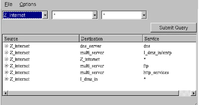
The next query is probably the first one any security ad-ministrator would submit: “How much access does the In-ternet have to the internal network?”. The results are shown in Figure 5. The first five lines are not so interesting. We know that any host on the Internet has some restricted ac-cess to the servers on the DMZ. Furthermore, from Fang’s point of view, any host in the Internet zone can speak to any other host in that zone, which explains the third line. The last line, however, indicates a weakness in the imple-mentation of the security policy. This line tells us that any host on the Internet can potentially open any service with the inner interface of the external gateway. Examination of the topology file will reveal the problem: The outer in-terface,I internet dmz, does not perform any filtering, and once packets have entered the gateway through it, they can speak to the other interface without any filtering. A
Figure 4. Fang results for a simple query.
more prudent approach, that solves this vulnerability, is to attach the rule-base to the outer interface rather than to the internal one.
The last query illustrates how to check for spoofing. The most sensitive host is probably the firewall administrator, so we would like to be sure that no Internet host can reach it, even with spoofing. To do this, we set the real source to be the Internet zone, and let the given source (the spoofed ad-dress) be arbitrary. The results are shown in Figure 6. The leak that they indicate, is actually a result of the same prob-lem seen in the previous query. An Internet host can create a message with the source address of theI dmz in inter-face. No filtering is done on the outer interface, and once inside, the packet is considered as if it originated from the
I dmz ininterface itself and will be let through because it matches one of the rules.
5
Future Work
A useful extension of the current query-answer mech-anism is to maintain and allow access to more informa-tion about a query. For instance, which rule in which in-terface is responsible for passing or dropping a particular packet. Such information can displayed graphically to show the path packets take from source to destination.
A more substantial extension is to enhance Fang to en-able topology independent queries via, e.g., defining zones as being “internal” or “external”. If we also enable Fang to read in queries from a file, the user would then be in
a position to use expert-generated queries to test the net-work for some basic insecurities. The expert queries might cover well-known insecure ports or services and test ac-cessibility of such ports from the external zones. As new vulnerabilities become known, organizations such as CERT could make updated query files available on their web-site for downloading.
6
Conclusion
We have described the design and implementation of Fang, our firewall configuration analysis tool. We have shown its inner workings and how it meets our design goals of Adequate Level of Abstraction, Do No Harm, Efficiency, and Ease of Use. We have shown in a complete example the usefulness of a tool with this design. We expect Fang’s ap-proach to become a highly valuable complementary option to active vulnerability testing.
References
[1] J. P. Anderson, S. Brand, L. Gong, T. Haigh, S. Lipner, T. Lunt, R. Nelson, W. Neugent, H. Orman, M. Ranum, R. Schell, and E. Spafford. Firewalls: An expert roundtable.
IEEE Software, 14(5):60–66, Sept./Oct. 1997.
[2] Y. Bartal, A. Mayer, K. Nissim, and A. Wool. Firmato: A novel firewall management toolkit. In Proc. 20th IEEE
Symp. on Security and Privacy, pages 17–31, Oakland, CA,
Figure 5. Fang results for a more interesting query.
[3] D. B. Chapman and E. D. Zwicky. Building Internet
Fire-walls. O’Reilly & Associates, Inc., 1995.
[4] Check Point FireWall-1, version 3.0. White paper, June 1997. http://www.checkpoint.com/products/
whitepapers/wp30.pdf.
[5] W. R. Cheswick and S. M. Bellovin. Firewalls and
Inter-net Security: Repelling the Wily Hacker. Addison-Wesley,
1994.
[6] M. K. Dalheimer. Programming With Qt. O’Reilly & Asso-ciates, Inc., 1999.
[7] D. Farmer and W. Venema. Improving the security of your site by breaking into it. http://www.porcupine.
org/wietse.
[8] M. Freiss. Protecting Networks with SATAN. O’Reilly & Associates, Inc., 1998.
[9] C. Fulmer. Firewall product overview. http://www.
waterw.com/˜manowar/vendor.html, Aug. 1999.
[10] Cisco IOS firewall feature set, Aug. 1999.
http://www.cisco.com/univercd/cc/td/
doc/pcat/229.htm.
[11] T. A. Limoncelli. Tricks you can do if your firewall is a bridge. In First USENIX Conference on Network
Adminis-tration (NETA), Santa Clara, CA, Apr. 1999.
[12] Lucent managed firewall, version 3.0, 1999. http://
www.lucent.com/iss/html/technical.html.
[13] Cisco NetSonar 2.0, May 1999. http://www.cisco. com/univercd/cc/td/doc/product/iaabu/
netsonar/.
[14] Cisco PIX firewall series, Aug. 1999. http: //www.cisco.com/univercd/cc/td/doc/
pcat/192.htm.
[15] Qt online reference documentation, version 2.0.1. Troll Tech, 1999.http://www.troll.no/qt/.
[16] M. Ranum. On the topic of firewall testing.http://www.
clark.net/pub/mjr/pubs/fwtest/index.htm.
[17] A. Rubin, D. Geer, and M. Ranum. Web Security
Source-book. Wiley Computer Publishing, 1997.
[18] W. R. Stevens. TCP/IP Illustrated, Volume 1: The Protocols. Addison-Wesley, 1994.
[19] K. M. Walker and L. Croswhite Cavanaugh. Computer
Se-curity Policies and SunScreen Firewalls. Sun Microsystems