September, 2015 Page 1 of 15
LEDs for Flash Applications
Application Note
Abstract
This application note introduces LEDs with optimized characteristics which are primary suitable for use as a camera flash.
In addition to a short summary of the common advantages of LEDs and the re-quirements of camera flashes, the most important parameters are described with reference to the operating mode.
Beyond that several assembly possibilities are shown including their thermal descrip-tions and some simulation results for the LUW FQ6N in flash operating mode are provided.
Introduction
The ambient light available for taking a picture often is insufficient in everyday situations, so it requires the use of a flash unit as an additional light source.
Due to their increasing brightness, LEDs are suitable to replace, for example, the conven-tional flash tubes used in flash units of mobile phones or digital cameras. During the last few years LEDs as camera flashes became more and more state-of-the-art in mobile phone applications.
In comparison to flash tubes, LEDs provide several advantages. A Traditional flash unit consists of a flash tube in which a flash is created by means of a gas discharge. The flash tube contains an inert gas, usually xenon or krypton.
Using a suitable circuit, the battery charges a capacitor to a level of a few hundred volts. This is then stepped up to a secondary voltage in the kV range by means of an ignition coil. This ignition voltage is released in the flash tube, causing the gas to ionize.
The flash arises through recombination and lasts only a fraction of a second. During this time a few hundreds amperes of current flow.
The light emitted from the flash tube exhibits a continuous spectrum which is similar to the sunlight’s spectrum (a Planck emitter in the color temperature range of 5500 – 6500K). Modern flash units contain a sensor, in which the reflected light from the subject is measured by means of a photodiode. The flash is automatically switched off after a predetermined amount of light is sensed. In this case, LEDs offer a particularly optimal light source for mobile devices. Due to the rapid development in the area of semicon-ductor technology in recent years, LEDs possess a very high brightness and addi-tional key features:
Advantages of LEDs
High mechanical stability Small dimensions Low voltage required to create a flash, compared to flash tubes
No charging time – the flash is immedi-ately available
Longer lifetime than conventional flash tubes
September, 2015 Page 2 of 15 Longer flash duration possible, up to
continuous mode
Multichip-LED adjustable color tempera-ture, adaptable spectrum
Flash Requirements
Depending on the application, various demands are placed on the camera flash in order to achieve a correct exposure. This leads to differing requirements which must be fulfilled, however.
1. Conventional Xenon Flash
Xenon photographic flash units are capable of illuminating subjects up to 45 meters away. The coverage range is regulated by the flash power.
Figure 1 shows the discharge curve for a typical conventional flash unit at maximum power.
Figure 1: Light output over time of a Xenon flash unit at maximum power
A sharp rise in light intensity is visible, followed by decay. Depending on the distance between the camera and the subject, a particular quantity of light is required for a proper exposure.
The quantity of light is defined to be the product of the illuminance and the flash duration, which corresponds to the integral of the area under the discharge curve. The quantity of light (flash power) can be controlled by the flash duration. For that purpose, the flash discharge and thus the discharge curve is prematurely interrupted.
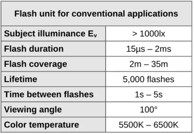
Conventional flash units illuminate a subject with an illuminance of more than Ev > 1000 lx. The flash duration varies from 15µs to 2ms, depending on the coverage range. The period between two flashes ranges from 1s to 5s. This period is necessary in order to recharge the capacitor. The color temperature of the flash is between 5500K and 6000K.
Conventional flash units have a lifetime of about 5,000 flashes. Afterwards, the bright-ness is reduced to a level of 90%.
Table 1 summarizes the requirements of a flash unit used for conventional applications.
Flash unit for conventional applications Subject illuminance Ev > 1000lx
Flash duration 15µs – 2ms
Flash coverage 2m – 35m Lifetime 5,000 flashes
Time between flashes 1s – 5s
Viewing angle 100°
Color temperature 5500K – 6500K
Table 1: Flash unit for conventional applications
2. Flash units for mobile phones
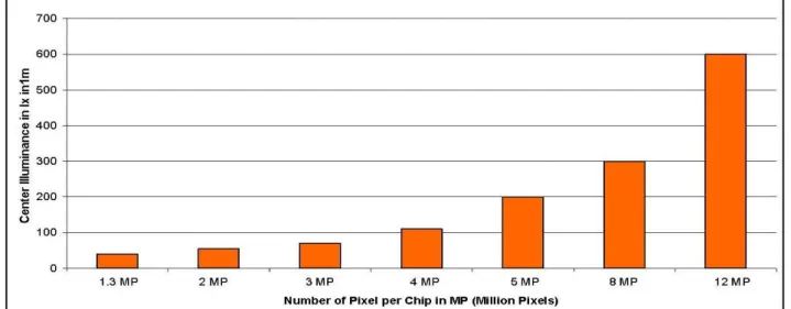
In mobile phones, the minimal illuminance depends on the optical resolution of used camera chip (Fig. 2).
Nowadays, camera modules with between 3 and 5MPixel are used as standard for most mobile devices. For these, the minimal center illuminance should be from 80lx to 200lx at 1m.
For the currently high end devices with 8MPixel or more, the light requirements are even higher, starting at 300lx.
However depending on the customized uniformity demand of the illuminated target area the light level in the center can vary from the given values.
September, 2015 Page 3 of 15
Figure 2: Typical center illuminance in 1m vs. resolution of the camera chip
Moreover in most applications, the flash should cover a rectangular field of view, e.g. 55° x 43°. In the center of this field, the requested illuminance level should be achieved. The illuminance in the corner of this field of view is, dependent on the desired homogeneity, around 20% to 40%. The required flash duration is in the range of up to 400ms. Depending on the processing rate of the mobile phone, the time between flashes is usually about 2.5s, although this can be shorter. The duty cycle of a flash is given by pulse duration divided by the cycle time (pulse duration plus break).
Due to the long integration time of typical CMOS image sensors (around 300 ms), an appropriate light source should ideally be capable of outputting a flash in the form of a square impulse (Fig. 3).
0 20 40 60 80 100 0 200 400 600 800 1000 1200 Time [ms] re l. B ri g h tn e s s [ % ]
Figure 3: Ideal square impulse of a flash module
The lifetime of the flash unit is assumed to be higher than 30,000 flashes.
LEDs for Flash Applications
Currently in the market only white LEDs from the multitude of available LED-types are used for camera flashing.
White LEDs are typically based on the principle of color addition, in which the primary color blue (blue semiconductor chip) and the appropriate complimentary color yellow (yellow converter) are used to create white light. The resulting color mixture respectively the color temperature is thereby already specified during production. The typical color temperature of white LEDs is in the range of 5000K to 7000K.
In addition to the function of digital image sensors (CCD or CMOS), multi color LEDs may be also suited for use as camera flash. In the following, white LEDs which can be considered for use as a substitute for flash tubes are presented.
Like all LEDs from OSRAM Opto Semiconductors, these LEDs fulfill the applicable RoHS guidelines and contain neither lead nor other banned substances. All shown LEDs are compatible with existing industrial SMT processing methods, so that all current populating techniques can be used for the mounting process. The individ-ual soldering conditions according to JEDEC can be found in the respective data sheet.
September, 2015 Page 4 of 15 To reach the optimal performance of the
LEDs, thermal management should be considered.
Since OSRAM Opto Semiconductors con-tinually makes improvements to the semi-conductor chip technology, especially at the luminous intensity of LEDs, please check the data sheets of the following LED types for further details and the latest performance data (www.osram-os.com).
OSLUX - LUW FQ6N
The LUW FQ6N is especially developed for camera flash applications with high de-mands on brightness combined with limited dimensions (4mm x 3.9mm x 2.45mm). The LED is constructed with a metal lead frame (Cu-Alloy) in contact with a semicon-ductor chip and housing with an integrated lens (Fig.4). The electrical contacts are located underneath the lead frame.
The chip bases on the newest ThinGaN technology and provides excellent color uni-formity as a result of the front emitter behavior combined with color conversion at the chip level.
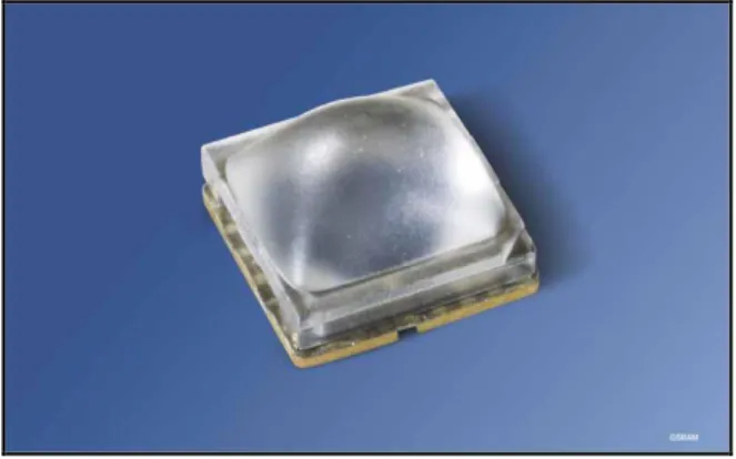
Figure 4: OSLUX LUW FQ6N
The integrated optics consists of a molded lens which is fixed to the LED frame. According the specification the target of the lens design is thereby aligned to maximal illuminance in the center with adequacy uniformity of the viewing area (Fig. 5).
Figure 5: Rectangular Illumination pattern of the OSLUX LUW FQ6N at 1m distance
Table 3 shows the electrical and optical characteristics of the LUW FQ6N.
OSLUX – LUW FQ6N
If 350mA 500mA 700mA 1000mA 1.5A 2.0A
v (typ.) 98lm 130lm 169lm 218lm 300lm 350lm
Ev avg. at 1m 120lx 159lx 206lx 266lx 366lx 427lx
Uf (typ.) 3.25V 3.3V 3.45V 3.55V 4.0V 4.2V
Max. Pulse duration
[Ta=25°C, D=5%)] > 10s 8s 2,5s 600ms 200ms 20ms
September, 2015 Page 5 of 15 Due to the optimized low thermal resistance,
the LED can be driven with a current of up to 2 A in pulse mode.
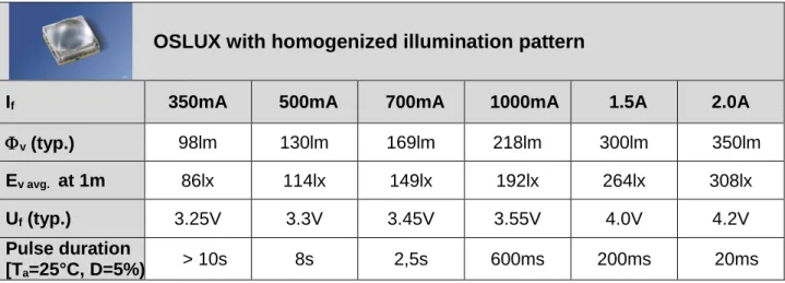
In line with demand the OSLUX LED is also available in a second version with varied lens design and adapted optical characteristics. The target of the additional lens shape is aligned to a good uniformity of the viewing area with adequacy illuminance level (Fig. 6)
Figure 6: OSLUX with homogenized illumination pattern at 1m distance
Table 4 shows the characteristics for this version of the OSLUX LED.
Overall, the OSLUX LUW FQ6N exhibits a superior efficiency and an excellent thermal characteristic.
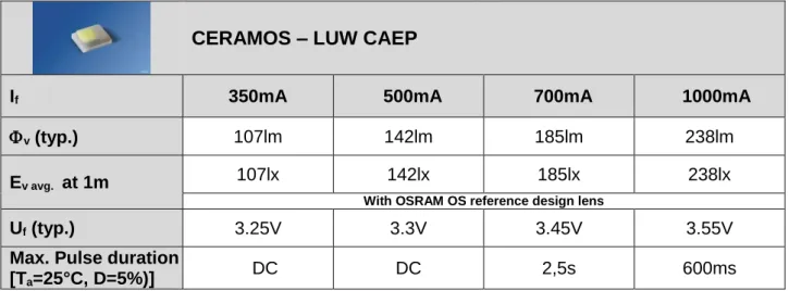
CERAMOS - LUW CAEP
This LED is a combination of minimized package and the newest high efficient ThinGaN chip technology with excellent color homogeneity.
Figure 7: CERAMOS LUW CAEP
Especially designed for applications with extremely limited space the LED exhibits a very high luminous brightness with a dimen-sion of 2.04mm x 1.64mm x 0.75mm.
The LUW CAEP consists of a ceramic substrate with the bonded chip on it, and an encapsulant of silicone. The electrical contacts are located underneath the ceramic substrate (Fig. 7).
The LED is ruggedized and suitable for pulse currents up to 1000mA.
Table 5 shows the optical and electrical characteristics of the LUW CAEP.
OSLUX with homogenized illumination pattern
If 350mA 500mA 700mA 1000mA 1.5A 2.0A
v (typ.) 98lm 130lm 169lm 218lm 300lm 350lm
Ev avg. at 1m 86lx 114lx 149lx 192lx 264lx 308lx
Uf (typ.) 3.25V 3.3V 3.45V 3.55V 4.0V 4.2V
Pulse duration
[Ta=25°C, D=5%) > 10s 8s 2,5s 600ms 200ms 20ms
September, 2015 Page 6 of 15
CERAMOS – LUW CAEP
If 350mA 500mA 700mA 1000mA
v (typ.) 107lm 142lm 185lm 238lm
Ev avg. at 1m 107lx 142lx 185lx 238lx
With OSRAM OS reference design lens
Uf (typ.) 3.25V 3.3V 3.45V 3.55V
Max. Pulse duration
[Ta=25°C, D=5%)] DC DC 2,5s 600ms
Table 5: Characteristics of CERAMOS
Similar to other toplookers without lens, the CERAMOS LED has a viewing angle of 120° with a Lambertian characteristic (Fig. 8).
Figure 8: Radiation characteristic of LUW CAEP
The LED can be easily combined with secondary optics e.g. a Fresnel lens to focus the light in the center of the viewing field. This optics is commonly fixed in the cover of the mobile phone.
LED Characteristics Related to
Flash Operation
In order to determine whether a LED is suitable for use as a camera flash, various characteristic optical properties should be considered. These include
Luminous flux of the LED Illuminance
Radiation characteristics Flash Duration
Brightness behavior with respect to flash duration
Switching time Color coordinates
In comparison to other LEDs the interaction of the individual values has also to be observed.
Brightness and Illuminance
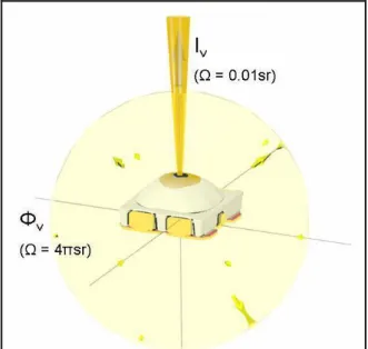
When characterizing LEDs, the brightness is usually stated as one of two values - luminous flux v (units of lm) or luminous intensity Iv (units of cd).
The luminous flux of an LED is defined as the total light output, independent of direction (Fig. 9).
Luminous intensity reflects the amount of light within a specified solid angle in the direction of radiation (e.g. 0.01 sr = 3.2°, see Fig. 9).
September, 2015 Page 7 of 15
Figure 9: Definition of luminous flux and luminous intensity
The two characteristic values v and Iv are only conditionally suitable for the characteri-zation of flash LEDs.
With regard to the application, the photomet-ric value for luminous flux density Ev (units of lx = lm / m²) is most often used. Illuminance describes the luminous flux for a specific area at a specific distance (Fig. 10).
Figure 10: Definition of illuminance Ev
When comparing illuminance values from various LEDs, the distance at which the values were obtained must be taken into account, since illuminance is reciprocal proportional to the square of the distance.
2
)
(
r
I
r
E
v v
(photometric distance law)
This means for example, that when the distance is doubled, the illuminance de-creases by a factor of four.
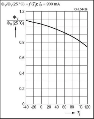
Due to the physical behavior of the semiconductor diode, the luminous flux of an LED does not increase or decrease linearly with the forward current applied and is also temperature-sensitive.
This means that if the luminous flux at a specified value is to be doubled, for example, the forward current must be increased by an additional factor.
Temperature dependency means that at higher temperatures, less light is produced by the LED.
The impact of both effects can be seen in following diagrams (Fig. 11 & 12).
Figure 11: Relative luminous flux vs. current (e.g. LUW FQ6N)
Furthermore, it should be noted that the measured illuminance only represents the brightness at the center of the LED or illumination field. Outside the center, illuminance level falls off more or less sharply, depending on the radiation charac-teristics of the particular LED or the additionally used lens.
September, 2015 Page 8 of 15 In order to achieve a uniform illumination
and thus positively influence the image quality, the entire image area should be nearly homogeneously illuminated.
Figure 12: Relative luminous flux vs. temperature (e.g. LUW FQ6N)
Radiation characteristics
Detailed information about the angle-dependent distribution of the luminous inten-sity respectively radiation is given by the radiation characteristic of the LED (Fig. 13).
Figure 13: Radiation characteristic of the OSLUX LUW FQ6N
The radiation characteristic of a LED is affected by its respective structure and is component specific for this reason.
Thereby the form of the radiation pattern can be influenced within a certain range by a lens directly on the top of the LED or by a separate secondary optics.
For instant SMD LEDs without lens show usually a Lambert' radiation characteristic, SMD LEDs with a simple spherical lens feature a more or less focused radiation. Generally concerning the lens effect, two different aspects can be purposed - homogenization or focusing.
During the homogenization by an appropri-ate lens design a leveling of the radiation behavior is strived within a certain angle range. The larger the homogeneous range thereby is the lower is the light and/or density of light in the center.
In contrast during the focusing a collimating of the radiated light is sighted.
In Figure 14 the interrelation between ho-mogeneity and illuminance in the center is once more illustrated on the basis of one LED with different lens characteristics.
Flash Duration
The quantity of light produced by a flash is determined from the product of the flash duration and illuminance Ev. With a higher illuminance of the LED, a shorter flash duration is required for a sufficient exposure. In order to reduce blurring, the flash duration should be kept as short as possible.
Brightness behavior within the flash duration
When power is applied to a LED, the forward voltage reaches a maximum followed by a rapid drop. Initially, the LED is dark and begins operation at room temperature. Due to the current, the brightness decreases as the LED becomes warmer. The slight decline starts when the LED warms up and the heat is transferred within the PCB. The behavior becomes saturated when thermal equilibrium is achieved between the PCB and the surrounding environment.
September, 2015 Page 9 of 15
Figure 14: The trade-off between center illuminance and homogeneity
The higher the LED current is the sharper is the decrease in brightness. The time required to reach thermal equilibrium is dependent on the PCB material used.
Nevertheless, the drop of brightness during the entire flash is around 10%, resulting in a nearly constant light level (Fig 15). The slight decrease can be compensated by the driving circuitry.
Because brightness decreases slightly over time, it is important to specify at what time the LED is measured when comparing different flash LEDs.
OSRAM Opto Semiconductors LEDs are measured as follows: After waiting around 5 ms for the current to stabilize, the brightness is measured for a short time period, typically 25 ms.
September, 2015 Page 10 of 15
Switching Time
White LEDs contain semiconductor chips based on InGaN technology. The switching time of InGaN dies is a few tenth of ns. The yellow converter responds approxi-mately a factor of 10 later. After this time, the light appears white to the eye.
Since the switching time of the converter is a factor of 106 shorter than that of the flash duration, the switching time of the converter does not need to be considered. Thus, it can be assumed that during the entire duration of the flash, white light is measured by the detector.
Color Coordinates
For most areas of photography, the color rendering index of white LEDs (typ. 80) is sufficient.
Figure 16 shows the spectrum of a typical ultra white LED. The dashed line indicates the standard eye response curve V().
Figure 16: Spectrum of typical ultra white LED (e.g. LUW FQ6N)
Within the professional sector, a higher color rendering index is required.
For these applications, the use of several different single-color or multi color LEDs, as well as white LEDs with multiband convert-ers, is recommended.
By enhancing the chromatic spectrum, the color rendering index can be significantly improved.
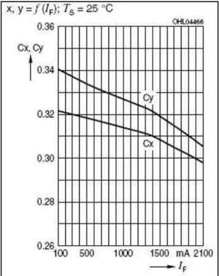
The forward current of standard white LEDs influences the chromaticity coordinate,
however. This relation can be seen in Figure 17. With increased forward current, the chromaticity coordinate shifts further into the blue range.
Figure 17: Chromaticity coordinate shift vs. forward current (e.g. LUW FQ6N)
Systems comparison
In the system the two presented LED types show their individual advantages and specifics, wherein they fulfill different requirements and conditions in the end. Related to the set-up, the OSLUX LEDs have the substantial advantage that due to the lens design no additional optics in application is needed. Thus the assembly and alignment to the window are substantially simplified. However the space requirement for the set-up is larger and the two LED versions provide only two specified radiation characteristics.
The CERAMOS LED in contrast scores in the set-up with its very small dimension and enables a higher flexibility by the determina-tion and definidetermina-tion of the radiadetermina-tion charac-teristic for the system due to the external auxiliary optics (Fig.18).
September, 2015 Page 11 of 15 If the lens is fixed in the cover, special
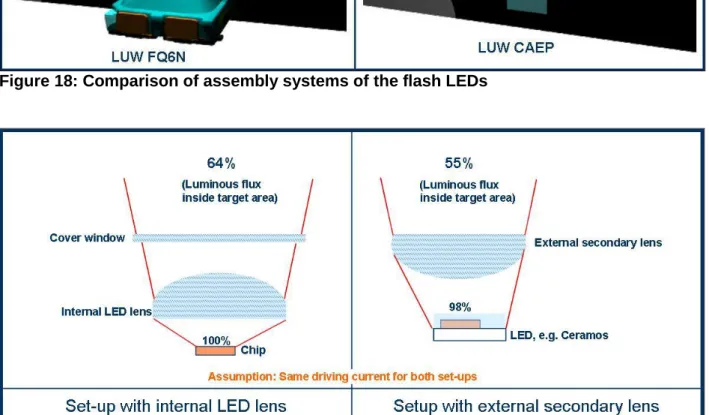
attention however must be given here to the alignment of the LED to the lens. A small offset of the LED for example is sufficient that the desired performance is not reached. In comparison of the total efficiency of both systems, it arises that in a set-up with integrated lens, as with the OSLUX LED, overall a higher luminous flux will be emitted to the target area, than in a system with external secondary lens (Fig. 19).
The main cause is that due to the Lambert' radiation of the toplooker LED only a limited portion of the available light can be collected into the external lens.
Thermal characteristics
An important feature of the LUW FQ6N is that the chip is directly mounted on the Cu-Alloy lead frame. Thus, the heat generated by the chip is transferred through the lead frame and can subsequently flow through the PCB to the environment.
This setup leads to a low thermal resistance for the LED of RthJS= 10.5 K/W (typical). Furthermore, due to the optimized low thermal resistance, the LUW FQ6N can be driven with currents up to 2 A in pulse mode in special cases.
In order to achieve optimal performance, thermal management should be considered. The assembly methods presented here were further examined with respect to their thermal properties and were thermally simulated in various modes of operation:
Figure 18: Comparison of assembly systems of the flash LEDs
September, 2015 Page 12 of 15 With regards to mounting on circuit boards,
three approaches were considered: 1. LED mounted on FR4 main PCB 2. LED mounted on Flex PCB 3. LED mounted on Flex on Al PCB This resulted in specification of the following boundary conditions for the thermal simulation:
Ambient Temperature: Tamb = 25°C Heat transfer coefficient of mobile phone
cover: α = 8 Wm-2K-1
Figure 20, 21 and 22 show the simulation setup of the three different PCB materials on which the LUW FQ6N is mounted. The material characteristics of the PCBs are given below.
The thermal simulation was done for 5 flash cycles with a flash pulse condition of
tP = 300 ms If = 1 A Interval 2s off
1. FR4 PCB
LED on multilayer main board PCB with 8 layers
PCB thickness 1.15 mm
Figure 20: LED on multilayer main PCB
2. Flexible PCB (15x8mm)
LED on separate Flex PCB Flex PCB with 2 layer
35 µm Cu, 50 µm PI, 35 µm Cu
Figure 21: LED on separate Flex PCB
3. Flexible PCB on Aluminum (10x8mm)
LED on Flex PCB with Al
PCB with 1 mm Al and 50 µm adhesive
Flex PCB with 35 µm Cu, 50 µm PI
Figure 22: LED on separate Flex on Al PCB
The results of the thermal simulation are shown in Figure 23.
The simulation shows that after 5 pulses the junction temperature of the LED is still below the max. specified value of 175°C for all three set-ups.
Thereby the set-up on flexible PCB with 1mm Aluminum plate features the best thermal behavior and keeps the temperature of the chip nearly constant.
A similar behavior provides the multilayer main PCB with a good thermal conductor for the flash operation, but on a higher temperature level.
In comparison with that the junction temperature of the LED mounted on a Flex PCB increases continuous during the flash operation. Nevertheless after 5 pulses, the maximum allowable junction temperature of 175°Cis still not exceeded.
September, 2015 Page 13 of 15
Figure 23: Comparison of different PCB materials for flash operation (LUW FQ6N)
Conclusion/Summary
In general, the requirements for the use of an LED as a camera flash can already be fulfilled and/or exceeded by current LED technology, especially for applications in mobile phones.
Furthermore, in contrast to conventional flash tubes, LEDs exhibit significant advan-tages such as improved shock resistance, small dimensions, low energy requirements, and a higher lifetime. In addition, no charg-ing time is required for the LED flash.
For best optical and electrical performance of LED camera flashes, the typical properties of the semiconductor chips such as thermal behavior and effects should be taken into account.
The presented LEDs, OSLUX and CERAMOS, are exceptionally suited for use as a camera flash in mobile phones.
Especially developed and optimized for this application, the OSLUX fulfills the require-ments regarding brightness, color homo-geneity and uniform illumination. With its
integrated lens, it exhibits the best optical performance as well as system efficiency. Depending on the requirements of the application, the CERAMOS LUW CAEP is also suitable for a use as camera flash. Due to its individual advantages, e.g. smaller space requirements, highest luminance and the possibility to generate individual illumina-tion patterns with auxiliary optics it fulfills many requirements for a wide range of applications (e.g. mobile and video).
Besides their use in flash units, the LEDs are also well suited as a flash lamp for video cameras. The advantage in this case is that the flashes can be synchronized to the video frames; the flash only activates during frame capture. Between frames, the flash is turned off. Compared to common video lamps for video cameras, this results in a lower energy usage.
The further development of LEDs will lead to higher efficiency and more light output. At the same time, the required forward current and the dimensions can be reduced.
September, 2015 Page 14 of 15 As OSRAM Opto Semiconductors will
continually develop improvements to the LED, please check the data sheets of the
LED types for the latest performance data (www.osram-os.com).
Appendix
Don't forget: LED Light for you is your place to be whenever you are looking for information or worldwide partners for your LED Lighting project.
www.ledlightforyou.com
Revision History
Date
Revision History
Sept. 2010 Publishing of application note
Sept. 2015 Change of Company Info & Disclaimer
Authors: Andreas Stich, Roland Fischl, Rainer Huber
ABOUT OSRAM OPTO SEMICONDUCTORS
OSRAM, Munich, Germany is one of the two leading light manufacturers in the world. Its subsidiary, OSRAM Opto Semiconductors GmbH in Regensburg (Germany), offers its customers solutions based on semiconductor technology for lighting, sensor and visualization applications. OSRAM Opto Semiconductors has production sites in Regensburg (Germany), Penang (Malaysia) and Wuxi (China). Its headquarters for North America is in Sunnyvale (USA), and for Asia in Hong Kong. OSRAM Opto Semiconductors also has sales offices throughout the world.
September, 2015 Page 15 of 15
DISCLAIMER
PLEASE CAREFULLY READ THE BELOW TERMS AND CONDITIONS BEFORE USING THE INFORMATION SHOWN HEREIN. IF YOU DO NOT AGREE WITH ANY OF THESE TERMS AND CONDITIONS, DO NOT USE THE INFORMATION.
The information provided in this general information document was formulated using the utmost care; however, it is provided by OSRAM Opto Semiconductors GmbH on an “as is” basis. Thus, OSRAM Opto Semiconductors GmbH does not expressly or implicitly assume any warranty or liability whatsoever in relation to this information, including – but not limited to – warranties for correctness, completeness, marketability, fitness for any specific purpose, title, or non-infringement of rights. In no event shall OSRAM Opto Semiconductors GmbH be liable – regardless of the legal theory – for any direct, indirect, special, incidental, exemplary, consequential, or punitive damages arising from the use of this information. This limitation shall apply even if OSRAM Opto Semiconductors GmbH has been advised of possible damages. As some jurisdictions do not allow the exclusion of certain warranties or limitations of liabilities, the above limitations and exclusions might not apply. In such cases, the liability of OSRAM Opto Semiconductors GmbH is limited to the greatest extent permitted in law.
OSRAM Opto Semiconductors GmbH may change the provided information at any time without giving notice to users and is not obliged to provide any maintenance or support related to the provided information. The provided information is based on special conditions, which means that the possibility of changes cannot be precluded.
Any rights not expressly granted herein are reserved. Other than the right to use the information provided in this document, no other rights are granted nor shall any obligations requiring the granting of further rights be inferred. Any and all rights and licenses regarding patents and patent applications are expressly excluded.
It is prohibited to reproduce, transfer, distribute, or store all or part of the content of this document in any form without the prior written permission of OSRAM Opto Semiconductors GmbH unless required to do so in accordance with applicable law.