An Industrial Case Study - Control of
BeoSound 9000 Sledge System
Zhenyu Yang
Department of Computer Science and Engineering, Aalborg University Esbjerg, Niels Bohrs Vej 8, DK-6700 Esbjerg, Denmark. yangcs.aaue.dk
Abstract
Mode-based control design of the sledge system of a BeoSound 9000 CD-player system produced by Bang & Olufen A/S is discussed. The sledge system is modeled theoretically and then system coefficients are identified through experiments. The obtained model is validated. Several control methods, namely digital PID control, digital PI control with anti-windup, and observer-based state feedback with integral control, are developed and then implemented in a TI MSP430F149 microprocessor. The test results show that both systems controlled by the digital PI control with anti-windup and the observer-based state feedback with integral control satisfy re-quirements defined by the industrial partner - Bang & Olufsen A/S.
Key words: DC motor, mechanical sledge system, physical modeling, identification, state-space, PID control, anti-windup, state observer
1 Introduction
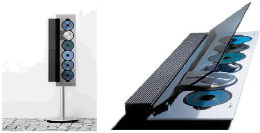
BeoSound 9000 is a high-end CD-player system developed and marketed by Bang & Olufen A/S in 1993. As shown in Fig.1, the BeoSound 9000 can be placed either horizontally or vertically on a stand. There are 6 CD slots in the BeoSound 9000. In order to move the optical pick-up unit to different CD slot positions, a sledge is constructed inside BeoSound 9000. There is a glass covering the entire CD-player system. In order to protect the optical pick-up system and users as well, the operation of the sledge system is designed to follow two defined modes:
• Slow mode - when the glass cover is opened, the sledge should move at a slow speed around 0.16m/s;
• Fast mode - when the glass cover is closed, the sledge should move at a high speed around 0.8m/s.
Fig. 1. BeoSound 9000 on its designated stand and its surface look
A touch sensor is built between the glass and the BeoSound9000 body so as to detect the glass cover position.
The current BeoSound9000 product uses a type of Panasonic DC-motor to drive the sledge system. The sledge speed is measured by a digital encoder at-tached on the motor shaft. The sledge position can also be determined using the encoder measurement if the starting position is known. Once the opti-cal pick-up unit carried by the sledge system reaches a desired position, two clamps on each side of the sledge will be activated to stop and hold the sledge system in place. Due to safety, these clamps will not be activated if the sledge speed is over 0.3m/s. The performance of the sledge system is expected to be as smooth as possible while keeping a proper speed profile at different modes.
Fig. 2. DC-motor and its digital encoder
A kind of PID controller apparently is used to control the sledge system, and the controlled system performances very well with a less than 10% oscillation when the sledge moves around a constant speed. However, due to some specific commercial reasons, Bang & Olufsen A/S decided that they will use another type of (Panasonic) DC motor as the driver for the BeoSound 9000 sledge
system in the near future. Unfortunately, some preliminary laboratory tests showed that the current PID controller doesn’t cooperate with the new selected motor very well, for example, the speed oscillation becomes up to 30% when the sledge should run at a constant speed, no matter the system is under slow or fast mode. Observing different features of these two types motors, Bang & Olufsen A/S would like to investigate the development and implementation of a new controller for the BeoSound 9000 sledge system possibly using some advanced but reliable control techniques, so as to re-achieve a satisfactory performance.
2 State of the Art
There are extensive studies on the control of optical disk drives [7]. For ex-ample, dual control of the sledge and voice coil motor is discussed in [8] so as to achieve precise radial tracking performance. [5,9] investigated the coupling between focusing and tracking dynamics. Robust control techniques such as H∞ control have been popularly employed for control design from a research
point of view [3,5,8,9]. However, there are few reported cases about this kind of advanced techniques being used in commercial products, one of the main reason is the heavy numerical complexity and conservative limitations. In the following, we will investigate several simple model-based control tech-niques for control of the BeoSound 9000 sledge system, namely, digital PID control, digital PI control with anti-windup, and an observer-based state feed-back with integral control. The developed controllers are implemented into a TI MSP430F149 microprocessor. Both simulation and real tests showed that the performances of the sledge system controlled by the PI control with anti-windup and the observer-based state feedback with integral control satisfy the requirements defined by Bang & Olufsen A/S.
3 Mathematical Model of the considered Sledge System
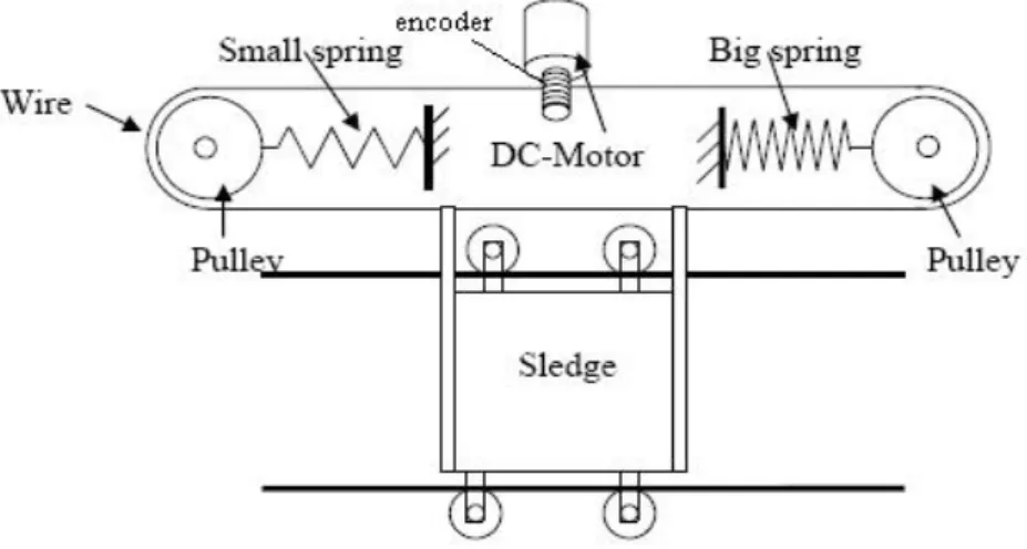
The BeoSound 9000 sledge system consists of a DC-motor, a mechanic sledge unit and a digital encoder. The schematic diagram of the sledge system is shown in Fig.3. In the following, firstly we model each component individually, then connect each part into a model of the entire system.
Fig. 3. Schematic diagram of BeoSound 9000 sledge system
Fig. 4. Schematic modeling of a DC motor 3.1 Modeling the DC-Motor
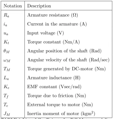
The standard linear model of a DC-motor as shown in Fig.4 is used here to model the new DC-motor proposed by Bang & Olufsen A/S [2,5]. The relevant system coefficients are listed in the following Table 1.
The electrical part of the DC-motor is described by
ua(t) =Ladia(t)
dt +Raia(t) +VEM F(t), (1)
whereVEM F(t) is the electromotive force (EMF) voltage. The mechanical part
of the DC-motor is described by
TM(t)−Tf(t)−Te(t) =JM
dωM(t)
dt . (2)
(1) and (2) are linked through the following torque and EMF equations:
Notation Description
Ra Armature resistance (Ω)
ia Current in the armature (A)
ua Input voltage (V)
Kt Torque constant (Nm/A)
θM Angular position of the shaft (Rad)
ωM Angular velocity of the shaft (Rad/sec)
TM Torque generated by DC-motor (Nm)
La Armature inductance (H)
Ke EMF constant (Vsec/rad)
Tf Torque due to friction (Nm)
Te External torque to motor (Nm)
JM Inertia moment of motor (kgm2)
TABLE 1 List of Coefficients for DC-Motor modeling
3.2 Modeling the Mechanical Unit
As shown in Fig.5, the mechanical part of the sledge system consists of the driving DC-motor, two pulleys, connection wire, suspension springs and the optical pickup unit (sledge). In the following, we assume
• the connection wire is inelastic and without mass;
• the suspension springs are assumed static, i.e., the centers of the two pulleys can never move;
• the two pulleys are identical.
The relevant system coefficients are listed in the following Table 2.
Notation Description
FSP1 Force on pulley 1 due to the sledge (N)
FSP2 Force on pulley 2 due to the sledge (N)
FM P1 Force on pulley 1 due to the DC-motor (N)
FM P2 Force on pulley 2 due to the DC-motor (N)
FP1S Force on sledge due to pulley 1 (N)
FP2S Force on sledge due to pulley 2 (N)
FP1M Force on DC-motor due to pulley 1 (N)
FP2M Force on DC-motor due to pulley 2 (N)
FS Force due to the friction affecting sledge (N)
TF P1 Torque due to the friction affecting pulley 1 (N)
TF P2 Torque due to the friction affecting pulley 2 (N)
rM Radius of the DC-motor shaft (m)
rP Radius of pulleys (m)
JP moment of inertia of pulley (kgm2)
θP1 Angular position of pulley 1 (Rad)
θP2 Angular position of pulley 2 (Rad)
Ms Mass of the sledge (kg)
x Position of the sledge on the track (m)
Φ Layout angle of BeoSound w.r.t. horizontal (deg.) TABLE 2 List of Coefficients for Mechanic Part Modeling
According to Newton’s laws, the dynamics of the DC-motor part can be de-scribed as
JM
d2θ M(t)
dt2 =TM +rM(FP1M −FP2M)−Tf. (4)
The dynamics of the two pulleys can be described as
JPd 2θ P1(t) dt2 =rp(FSP1−FM P1)−TF P1, JPd 2θ P2(t) dt2 =rp(FM P2−FSP2)−TF P2. (5)
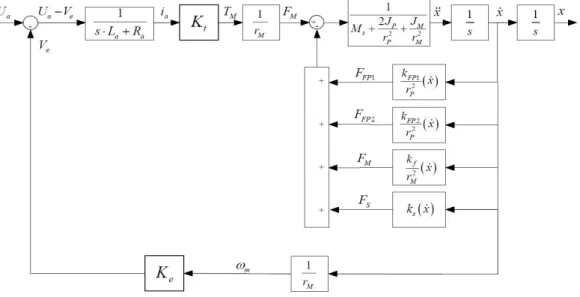
Fig. 6. Block diagram of entire sledge system
The dynamics of the optical pickup (sledge) can be described as
Ms
d2x(t)
dt2 =FP2S−FP1S−FS+mgsinΦ. (6)
If we assume the system is in a horizontal position, thenmgsinΦ = 0. By knowing the relationships
|FSP1|=|FP1S|, |FSP2|=|FP2S|, |FM P1|=|FP1M|, |FM P2|=|FP2M|, rpd 2θ P1 dt2 = d 2x dt2, rpd 2θ P2 dt2 = d 2x dt2, rMd 2θ M dt2 = d 2x dt2, (7)
the dynamics of the mechanical part can be described in a compact form as
Mt d2x(t) dt2 = 1 rM TM(t)−Ff(t), (8) whereMt = 2Jr2P P + JM r2 M +Ms, Ff(t) = 1 r2 P(FF P2+FF P1)− 1 r2 MFf−FS.Combining
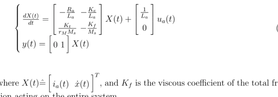
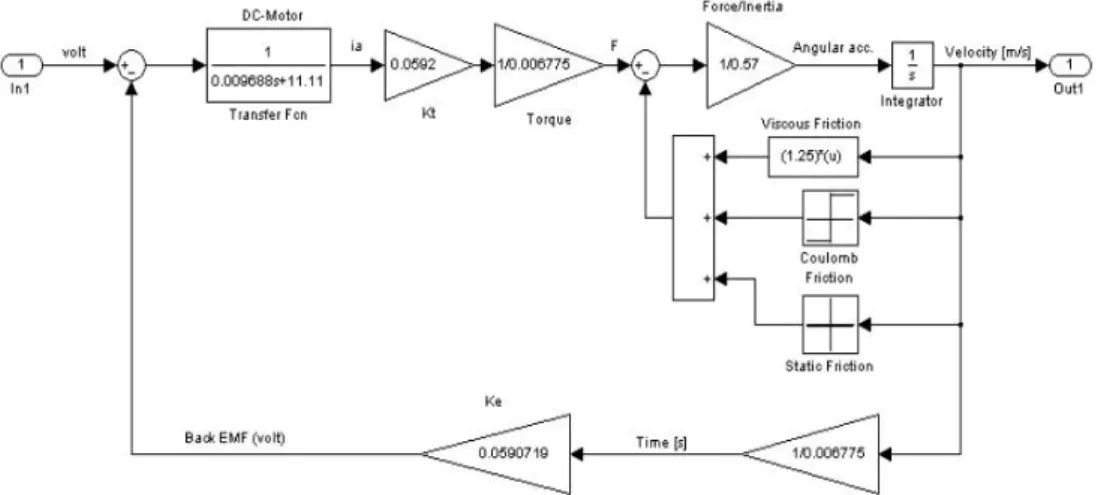
(1), (3) and (8), the model of the entire sledge system can be obtained. The block diagram of the entire system is shown in Fig.6, where the frictions are assumed to be speed dependent, i.e., considering only viscous frictions. Under
this assumption, a linear state space model of the considered system is dX(t) dt = − Ra La − Ke La Kt rMMs − Kf Ms X(t) + 1 La 0 ua(t) y(t) = · 0 1 ¸ X(t) (9) whereX(t) ˆ= · ia(t) ˙x(t) ¸T
, andKf is the viscous coefficient of the total
fric-tion acting on the entire system.
4 Parameter Identification
Several experiments are arranged so as to identify some unknown system pa-rameters, such as La,Kt (Ke),Mt and total system friction forceFf.
4.1 Identification of Motor Parameters
The armature coil resistance can be directly measured, which is Ra = 11.1Ω.
In order to identify the motor constant Kt (EMF constant Ke = Kt), the
considered motor is driven by another motor at a constant speed. Meanwhile, the angular velocity of the considered motor is measured by the digital encoder along with voltage over the armature terminals. The system coefficient Ke
is then estimated as Ke = Kt = 5.9e −2. The armature inductance La =
9.688mH is estimated through the time constant of a simple circuit as shown in Fig.7 where the output is the measured voltage over a serial connected resistor. This leads to La= 9.688mH for our case.
4.2 Identification of Mechanical Parameters
Due to its small value, the inductance of the used DC-motor can be neglected from (1). The torque generated by the DC-motor can then be estimated by
TM(t) = Kt Ra (ua−Ke ˙ x(t) rM ), (10)
where ˙x(t) denotes the speed of the sledge. Then (8) can be simplified as
MtrM d2x(t) dt2 = Kt Ra (ua−Ke ˙ x(t) rM )−rMFf(t).
We assume the force due to friction Ff(t) is linearly dependent on the speed,
i.e.,
Ff(t) =Kfx˙(t).
The analysis of this assumption is discussed in the following subsection. Then the transfer function from the input voltage ua(t) (Ua(s)) to the sledge speed
˙ x(t) ( ˙X(s)) is ˙ X(s) Ua(s) = KtrM Mtr2MRas+ (KtKe+rMKf) , (11)
where the system time constant is
τ=ˆ Mtr
2 MRa
KtKe+rMKf
. (12)
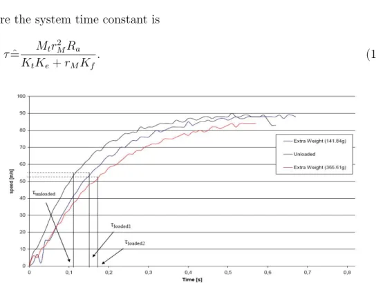
It is observed that Mt is only relevant to the time constant of the system
(11). However, so far the system parameter Kf is unknown. Therefore, an
experiment is arranged to identifyMtwithout influence ofKf: drive the sledge
system with a constant voltage input and measure the speed through the digital encoder. This experiment is done under different situations for which the masses of the sledge unit are different by adding extra known masses on top of the sledge unit. The time constants for different load situations can be determined based on experimental data as shown in Fig.8. For instance, according to (12), the time constant of a testing system with known load mex
is
τex=
(Mt+mex)r2MRa
KtKe+rMKf
. (13)
By combining (12) and (13), the massMt can be determined by
Mt=mex
τ τex−τ
. (14)
An average of results from several tests is used as the value of the system, it is Mt= 0.57kg.
4.3 Friction Analysis
There are two types of friction for mechanical movement that needs to be identified: static friction and dynamic friction [6]. The static friction is the stick force that the system needs to overcome in order to start moving. For the considered BeoSound 9000 system, the static friction is estimated by using a Newton meter, and it is Fstatic = 4.6N. The dynamic friction consists of
viscous friction which is speed dependent and coulomb friction which is a dry force. The viscous coefficient Kf is relevant to the steady-state step response
of system (11).
4.3.1 Viscous Friction
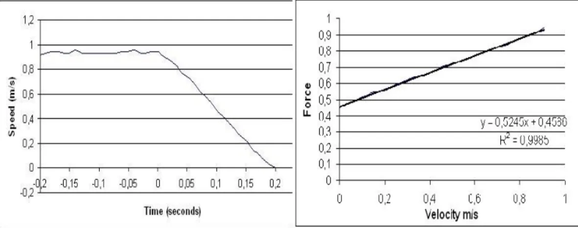
The viscous friction is measured using the free response analysis. The max-imum input 14v is applied to the DC-motor until the sledge system reaches a constant speed. Then power is switched immediately, meanwhile the sledge speed is recorded until the sledge stop. The measured speed is shown on the left figure in Fig.9. During the free response period, there are only friction forces (viscous and coulomb frictions) acting on the sledge system. By esti-mating the deceleration at several selected speed points for the free response
period and using the total mass Mt estimated in Section 4.2, then a figure
showing the relationship between the friction forces via speed is presented in Fig.9 (right figure). Through estimating the slope of the force-speed cure, the viscous coefficient thereby can be estimated.
Fig. 9. Measured speed of an inverse step response and the estimated viscous friction force
4.3.2 Coulomb Friction
The coulomb friction is always present during the movement. Once the viscous friction coefficient has been identified, the coulomb friction can be estimated using the measurement when the sledge moves at a constant speed. The basic idea is: When the sledge moves at a constant speed which can be measured through the encoder, there is the force balance, i.e.,
FM =kviscousx˙ +Fcoulomb, (15)
where FM is the force generated by the DC-motor acting on the wire. FM
can be estimated through FM = TrMM = KrtMia if the armature current ia can be
measured, if necessary, the calculated value can be verified by checking the current-to-torque cure in motor’s data-sheet.Then, using the measured sledge speed ˙x and the viscous coefficient estimated in last subsection, the coulomb friction can be estimated as Fcoulomb = FM −kviscousx˙. For our case, there is
Fcoulomb = 2.98N.
Finally, the friction part is estimated as
Ff( ˙x) = 1.25 ˙x(t) + 2.98, x˙(t)º0 1.25 ˙x(t)−2.98, x˙(t)¹0 4.6 x˙(t) = 0 (16)
The obtained testing curve is shown in Fig.10, where a linear approximation of this friction curve is also drawn.
Fig. 10. Friction curve of the entire sledge system
5 Simulation and Model Validation
The entire nonlinear system model with identified parameters is implemented in a Matlab/Simulink environment as shown in Fig.11. A linear model is also obtained based on the nonlinear model by taking a linear approximation of the nonlinear friction function (16). The simulation models are compared with the real system in terms of step responses at different input conditions. One result is shown in Fig.12. It can be observed that the nonlinear model reflect the real system dynamics very well, while the linear model has some offsets. In practice, these offsets can be eliminated by adding integral control into the controller’s structure if the controller is developed based on the linear model.
Fig. 12. Model validation under different input conditions
6 Control Design and Test Results
Several simple controllers are developed for the considered system. These con-trollers are implemented and tested in the physical system. It turned out that system performances under PI control with anti-windup and the observer-based state feedback with integral control satisfied all demands defined by the company.
6.1 Control Objectives
The following demands are proposed by Bang & Olufsen A/S regarding the dynamic performance of the sledge system.
• Traveling time: The sledge unit should move from position 1 to position 6 within 0.8 (4) second for the fast-speed (slow-speed) mode;
• The oscillation of the speed during the movement should be controlled around 10%;
• The sledge should slow down below 0.3m/s at its destination for the clamps to be activated.
6.2 Control Strategies
Since all demands discussed in the above subsection are relevant to sledge speed directly, the speed control strategy is employed here. First of all, a set
Fig. 13. A set of speed profiles for control under fast and slow modes
of desired speed profiles as shown in Fig.13 are set up regarding the travel time requirement and clamp speed limitation. The oscillation requirement is defined as an overshoot limitation (< 10%) over the step response for speed control design. Several control methods are employed for the sledge speed control design, namely
• Standard PID controller. The Ziegler-Nichols quarter decay ratio and ulti-mate sensitivity methods [2] are used to determine PID coefficients, respec-tively. A digital implementation isu(k) =u(k−1) +KP[(1 +TTsI+TTDs)e(k)−
(1+2TD
Ts )e(k−1)+
TD
Tse(k−2)], where the sampling periodTs is 0.004 second
for our case.
• PI controller with anti-windup. In order to explicitly control overshoot, the root locus method is used for further tuning of the P part of a developed PI controller based on the linearized model. Meanwhile, the anti-windup technique is also employed to handle the saturation problem of the DC-motor [4]. The control structure is shown in Fig.14. An implementation is
If umin < uc< umax, then
u(k) = u(k−1) +KP[(1 + TTsI)e(k)−e(k−1)];
If uc> umax oruc< umin, then
u(k+ 1) = [1− TsKa (1+Ka)TI]u(k) + KP 1+Ka(1 + Ts TI) e(k)− KP 1+Kae(k−1) (17)
where Ka is the slope coefficient of the anti-windup figure, which can be
obtained through trial and error. umin and umax are the lower and upper
Fig. 14. Structure of PI controller with anti-windup
• Observer-based state feedback with integral control. It is checked that the system (9) is observable and controllable. A full-order observer is designed so as to estimate the armature current ia based on the measured ˙x. The
observer gain is selected such that the observer is 10 times faster than the controlled system. The feedback gain and the integral gain can be combined into an augmented state space model, so that the pole placement design method is used to obtain these gains [2].
6.3 Results and Discussion
(1) From the test results , where KP = 1.9e+ 2, KI = 1.0e−3 and KD =
2.5e−4, it is observed that the sledge controlled by a PID controller developed by the Ziegler-Nichols quarter decay ratio method took a little bit over 4 sec to reach position 6 from the starting position 1 for the slow mode. There is no problem for the clamps to stop the sledge unit for the slow mode. However, the oscillation for most at the traveling period is about 25% for both slow and fast modes [1], which is not acceptable by the company. Similar results are also obtained for the fast mode study, where this oscillation also remains to be a problem for the fast mode
(2) In order to handle the big oscillations, the anti-windup technique [4] is combined with a PI controller, where KP = 2.09 and KI = 2.43e−1. The
test result for the slow mode is shown in Fig.16. It is noticed that the system performance satisfies all requirements. A comparison of this design with a feed-forward controller where the input voltage to the DC-motor is 6.5V is shown in Fig.17. It can be observed that the controller is able to overcome the irregularities caused by irregular friction [1].
The test result for the fast mode is shown in Fig.18. It is noticed that the system performance satisfies all requirements. The comparison of this design with a feed-forward controller where the input voltage to the DC-motor is
Fig. 15. Result using Ziegler-Nichols quarter decay ratio method for slow mode (X-axis is samples with sampling frequency 250 Hz
Fig. 16. Speed measurement for the slow mode using PI with anti-windup
Fig. 17. Performance comparison of PI (with anti-windup) with a feed-forward con-trollerua= 6.5V
12V shows that the controlled system has a faster response than the open-loop system, such that the traveling time is successfully limited within 0.8 seconds.
(3) The test results using the observer-based state feedback control with in-tegral control for the slow and fast modes are shown in Fig.19 and Fig.20, respectively. It can be noticed that both situations are satisfied except that
Fig. 18. Speed measurements for the controlled fast mode and comparison with open-loop controller ua= 12V
Fig. 19. Speed measurement for the slow mode using state space controller
Fig. 20. Speed measurement for the fast mode using state space controller
there are a few peaks in the slow mode over the 10% threshold, which we suspect is caused by irregular frictions due to wear out.
Comparing system performances using the PI control with anti-windup and the state space method, it can be observed that the state space method leads to a faster system than the PI control does for both slow and fast modes.
comparison PID and SS
Fig. 21. Speed measurements for the controlled fast mode and comparison with open-loop control
Fig. 22. Speed measurements for the controlled fast mode and comparison with open-loop control
7 Conclusions
Mode-based control design for the BeoSound 9000 sledge system is discussed. The considered system is modeled according to first modeling principle. Then, system parameters are identified through experiments. Several control meth-ods, namely digital PID, digital PI control with anti-windup, and observer-based state feedback with integral control, are developed and implemented into a microprocessor. The simulation and test results showed that both strategies of the digital PI control with anti-windup and the observer-based state feed-back with integral control lead the controlled system to satisfy all demands defined by the industrial partner. So far the efficiency of the developed con-trollers has not yet been investigated, it will be left for future work.
8 ACKNOWLEDGMENTS
The authors would thank H. F. Mikkelsen from Bang & Olufsen A/S for pro-viding the test system. Thanks also go to B. B. Nørregaard, K. D. Rasmussen, L. H. Andreasen, J. Laas, L. H.P. Andersen for some testing work.
References
[1] Lars H. Andreasen, Jacob Laas, and Lars H.P. Andersen. Sledge control for beosound 9000. 6th semester project, Aalborg University Esbjerg, Denmark, Denmark, May 2004.
[2] G.F. Franklin, J.D. Powell, and M. Workman.Digital control of dynamic systems. Addison-wesley, 1998.
[3] Kyung-Soo Kim. Analysis of optical data storage systems - tracking performance with eccentricity. IEEE Trans. on industrial electronics, 52(4):1056–1062, Aug 2005.
[4] M.V. Kothare, P.J. Campo, M. Morari, and C.N. Nett. A unified framework for the study of anti-windup designs. Automatica, 30(12):1869–1883, 1994.
[5] S. Lim and T.Y. Jung. Dynamics and robust control of a high speed optical pickup. Journal of sound and vibration, 221(4):607–621, 1999.
[6] Lennart Ljung and Torkel Glad. Modeling of Dynamic Systems. Prentice Hall, 1994.
[7] Philips Electronics N.V. and Sony Corp. Compact-Disc Digital Audio System description. Nov 1991.
[8] Rob M.G. Rijs, F.B. Sperling, and M. Steinbuch. Sido controller design for a high performance optical drive. InProc. of American Control Conference, pages 2633–2638, Chicago, Illinois, Jun 2000. IEEE.
[9] T.J. Yeh and Y.C. Pan. Modeling and identification of opto-mechanical coupling and backlash nonlinearity in optical disk drives. IEEE Trans. on consumer electronics, 46(1):105–115, 2000.