USB-Link™ 2
Wi-Fi Edition
Installation and
Setup Manual
sublicensed or transferred without the prior written consent of IDSC Holdings LLC.
This manual, as well as the software it describes, is furnished under license and may only be used or copied in accordance with the terms of such license. The content of this manual is furnished for informational use only, is subject to change without notice, and should not be construed as a commitment by IDSC Holdings LLC. IDSC Holdings LLC assumes no responsibility or liability for any errors or inaccuracies that may appear in this book. Except as permitted by such license, no part of this publication may be reproduced, or transmitted, in any form or by any means, electronic, mechanical, or otherwise, without the prior written permission of IDSC Holdings LLC.
NEXIQ Technologies and USB-Link are trademarks of IDSC Holdings LLC.
©2015 IDSC Holdings LLC. All rights reserved. All other marks are trademarks or registered trademarks of the respective holders. Pictures for illustration purposes only. Specifications are subject to change without notice. www.nexiq.com
This device complies with Part 15 of the FCC Rules. Operation is subject to the following two conditions: (1) this device may not cause harmful interference, and (2) this device must accept any interference received, including interference that may cause undesired operation. This device contains FCC-ID XPYELLAW161 / IC-ID 8595A-ELLAW161.
Approved in accordance to R&TTE directive transmitter module marked by “CE product label”, manufactured by u-blox AG.
USB-Link™ 2 Wi-Fi Edition Installation and Setup Manual iii
Chapter 1:
Using this Manual ...1
Manual Overview ...2
Conventions ...3
Chapter 2:
Introducing the USB-Link™ 2 Wi-Fi Edition ...5
Component Checklist ...6
Product Specifications ...7
System Requirements ...8
Communication Options ...9
Wired Connection ... 9 Wireless Connection ... 10Mini Access Point Mode (Peer-to-Peer) ... 11
Infrastructure Mode (Connecting to your Company’s Network) ... 12
Chapter 3:
Installing the Drivers and Setting Up the Device ...13
Installation Process Outline ...14
Step 1: Install the Drivers ...15
Step 2: Connect the USB-Link™ 2 to a Vehicle ...24
Connect Using a USB Cable ... 24
Connect Using Wi-Fi ... 25
Mini Access Point Mode ... 25
Step 3: Test the Connection ...29
Using the USB-Link™ 2 Explorer ...32
The Configuration Tab ... 34
USB-Link™ 2 Wi-Fi Edition Installation and Setup Manual 1
1
Using
this Manual
Manual Overview, page 2
Conventions, page 3T
his chapter provides an overview of this manual’s organization and the conventions used throughout.NOTE:
i
Screen shots used throughout this manual are for illustrative purposes only. All data shown is fictitious in nature.Manual Overview
This manual provides basic and detailed information to support you during instal-lation and setup of the USB-Link™ 2 Wi-Fi Edition.
This manual is composed of the following sections:
• Table of Contents—helps you to find the information you are looking for quickly and easily.
• Chapter 1: Using this Manual—provides an overview of this manual. • Chapter 2: Introducing the USB-Link™ 2 Wi-Fi Edition—introduces the
USB-Link™ 2 Wi-Fi Edition, and provides details regarding the commu-nication modes available to you to interface with your PC
• Chapter 3: Installing the Drivers and Setting Up the Device—provides in-structions for installing NEXIQ™ drivers and utilities, connecting the USB-Link™ 2 to a vehicle, connecting to a wireless network, and testing the connection. It also provides information on using the USB-Link™ 2 Explorer.
Each chapter begins with an “at-a-glance” list of the chapter contents, along with corresponding page numbers.
- Conventions
USB-Link™ 2 Wi-Fi Edition Installation and Setup Manual 3
Conventions
This section provides descriptions of the conventions used throughout this guide.
Special Messages
Note
NOTE provides an explanation, comment, or tip related to the subject matter that is being discussed.
Example:
NOTE:
i
Refer to the page number provided for each described component for fur-ther details.Important
IMPORTANT indicates a situation which, if not avoided, may result in damage to the test equipment or vehicle.
Example:
IMPORTANT:
ä
All RP1210 adapters must be disconnected before proceeding with installation.Caution
CAUTION indicates a potentially hazardous situation which, if not avoided, may result in moderate or minor injury to the operator or to bystanders.
Example:
CAUTION:
Warning
WARNING indicates a potentially hazardous situation which, if not avoided, could result in death or serious injury to the operator or bystanders.
Example:
WARNING:
ä
Keep all cables clear of moving or hot engine parts.Troubleshooting
Information intended to help you to address or anticipate potential issues are pre-sented in the following manner:
If NEXIQ WVL2 drivers are installed, the WVL2 Explorer Utility must be exited before proceeding with installation.
Specialized Text
The following specially formatted text is used to help you to differentiate certain elements discussed within this manual:
• Emphasis: Used to draw your attention to particularly important information.
• FEATURE: Used to highlight the name of a specific feature. Example: “Click on the Finish button to continue.”
• Field/Line: Used to highlight the name of a field or a line of text from a display.
Example: “A check mark is placed in the check box next to the Total Fuel Used parameter.”
• Menu Items: Used to highlight a series of menu selections.
Example: “From the Start menu, select Programs
NEXIQ
Device Tester
Device Tester.”USB-Link™ 2 Wi-Fi Edition Installation and Setup Manual 5
2
Introducing the
USB-Link™ 2
Wi-Fi Edition
Component Checklist, page 6
Product Specifications, page 7
System Requirements, page 8
Device Features, page 9
The Reset Button, page 10
Communication Options, page 11
Wired Connection, page 11
Wireless Connection, page 12
Mini Access Point Mode (Peer-to-Peer), page 13
Infrastructure Mode (Connecting to your Company’s Network), page 14T
he USB-Link™ 2 is a hardware device that enables service bay personal computers (i.e., PCs and/or laptops) to retrieve vehicle information using either Wi-Fi technology or a more traditional cable connection. Once configured, the USB-Link™ 2 interfaces with your PC, enabling you to use specific PC applications to perform vehicle diagnostics.This chapter introduces the USB-Link™ 2 and provides details regarding the communication modes available to you to interface with your PC.
Component Checklist
The following components are included with your USB-Link™ 2. Be sure you have all of the following items before using the device:
USB-Link™ 2 Vehicle Communication Interface (VCI)
Automotive A to Mini-B USB Cable
6- and 9-pin “Y” Deutsch Adapter
Carrying Case- Product Specifications
USB-Link™ 2 Wi-Fi Edition Installation and Setup Manual 7
Product Specifications
The USB-Link™ 2 is configured with the following specifications:
Feature Data
Physical Dimensions 6.75" x 3.75" x 1.06" (171 mm x 95 mm x 27 mm)
Weight 8 oz. (0.22 kg)
Power Requirements 6 - 32 VDC @ 350 mA maximum Operating Temperature 0 to +70 °C
API Driver TMC RP1210A, RP1210B, and RP1210C
compliant
SAE J2534 compliant Vehicle Protocols Supported • J1708/J1587
• J1939 (250K, 500K, or 1 MB) • CAN (125K, 250K, 500K, 1 MB) (3 CAN channels supported)
• J2284 CAN (125K, 250K, or 500K) • ATEC-160 Baud • ALDL Pass-through • ALDL 8192 • ALDL 9600 • OBDII • ISO 9141 • ISO 14230 (KWP2000) • ISO 15765 • J1850 (PWM, VPM, or Allison) • J1939 Auto Baud
• IESCAN (required for Allison) USB Communication USB Device, version 1.1
Wireless Communication Dual band Wi-Fi (802.11 a/b/g/n)
Wired Communication Automotive A to Mini-B USB cable 13 ft. (4 m) maximum
Vehicle Connector High Density D-sub 26-pin Male (HD26M)
System Requirements
Be aware of the following system requirements:
Component Requirement
IBM PC-compatible computer
• 1GHz processor or more
• RAM: 256MB or more (512MB recommended) • USB port, version 1.1 or higher
• Wi-Fi card Operating system • Windows® 7
• Windows® 8
Note: USB-Link™ 2 drivers support the
Windows® 8 operating system. However, not all OEM PC applications work with Windows® 8. Wi-Fi wireless
network
- Device Features
USB-Link™ 2 Wi-Fi Edition Installation and Setup Manual 9
Device Features
The following illustration details the features of the USB-Link™ 2 device.
B C D E A F Reset Button Figure 2.1 USB-Link™ 2 Legend
A—Vehicle Port D—Wireless LED
B—Power LED E—Fault LED
The following table outlines the features called out in Figure 2.1.
Feature What It Does
Vehicle Port Connects the USB-Link™ 2 to a vehicle. Power LED Illuminates when the device receives power. Data LED Illuminates when the device is receiving data from
the vehicle.
Wireless LED Mini Access Point Mode:
• Illuminates solid when a client PC connects to the device.
• Off when not connected. Infrastructure Mode:
• Stays off when not associated with an Access Point.
• Blinks every second when associated with a network but no IP address assigned.
• Illuminates solid when successfully assigned an IP address.
Fault LED Illuminates when a problem is detected. USB Port Connects the device to your PC (wired
connection).
The Reset Button
If you have configured your USB-Link™ 2 device in Infrastructure Mode (using the USB-Link™ 2 Explorer), you can use the Reset button on the bottom of the device to switch from Infrastructure Mode back to Mini Access Point Mode (the factory default). Just push and hold the button until all the lights on the front of the device flash, about five (5) seconds.
NOTE:
i
For detailed information on the USB-Link™ 2 Explorer, see Using the USB-Link™ 2 Explorer in Chapter 3 of this manual.- Communication Options
USB-Link™ 2 Wi-Fi Edition Installation and Setup Manual 11
Communication Options
Prior to using the USB-Link™ 2, you need to decide how you want the unit to com-municate with your PC. There are two options:
• A wired connection to the PC using a USB cable (pg. 11)
or
• A wireless connection to the PC using Wi-Fi(pg. 12)
Wired Connection
A USB connection provides several advantages. It’s easy to configure; you just plug it in. Also, there’s no confusion about which USB-Link™ 2 is connected to the PC (just follow the cable). Finally, a USB connection is not susceptible to radio fre-quency interference and provides higher communication reliability.
IMPORTANT:
ä
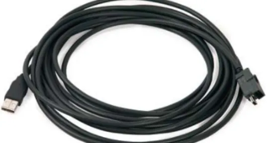
ECU reprogramming typically requires both high throughput and critical timing, and should always use a USB-to-PC wired connection.Wired communication between the USB-Link™ 2 and your PC requires an auto-motive A to Mini-B USB cable (shipped with the USB-Link™ 2).
Figure 2.2 Automotive A to Mini-B USB Cable
NOTE:
i
For detailed instructions on making a wired connection, refer to Connect Using a USB Cable, in Chapter 3 of this manual.Wireless Connection
Wireless connectivity provides untethered operation, and that’s a bonus in a busy service bay. The USB-Link™ 2 uses Wi-Fi to provide wireless communication between the USB-Link™ 2 and your PC.
There are two network options: • Mini Access Point (pg. 13)
• Infrastructure (pg. 14)
Wi-Fi performance can be affected by network congestion or radio frequency in-terference if there are too many other wireless devices in the vicinity.These conditions may result in dropped messages. For this reason, Wireless communi-cation is not recommended for ECU reprogramming (i.e, reflashing).
- Communication Options
USB-Link™ 2 Wi-Fi Edition Installation and Setup Manual 13
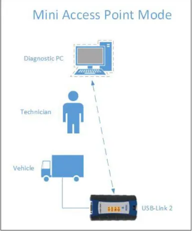
Mini Access Point Mode (Peer-to-Peer)
The easiest and quickest way to connect your USB-Link™ 2 to your PC is Mini Access Point mode. In Mini Access Point mode (also known as Access Point Em-ulation mode), the PC communicates directly with the Link™ 2. The USB-Link™ 2 emulates the function of an access point, allowing the PC to connect directly to the USB-Link™ 2, as if it were an access point. When the PC is con-nected to the USB-Link™ 2 in Mini Access Point mode, neither device is connected to the company network.
Figure 2.3 Mini Access Mode
If you use your PC’s internal wireless network card to connect to your company’s network and the Internet, you may want to obtain an additional wireless network card for use with the USB-Link™ 2. Otherwise when you connect the USB-Link 2 to your PC using Mini Access Point mode, you will not have access to the Internet until you have finished your session and reconnected to your company’s network.
For instructions on connecting the USB-Link™ 2 and your PC using Mini Access Point Mode, see Connect Using Wi-Fi, in Chapter 3 of this manual.
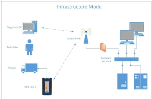
Infrastructure Mode (Connecting to your Company’s Network)
In Infrastructure mode, your PC communicates with your company computer network through a Wireless Access Point (not included), which acts as a bridge between the wireless network and the wired network. In this mode, the USB-Link™ 2 is configured to communicate with the same access point. All communi-cation between the PC and the USB-Link™ 2 passes through the access point.Figure 2.4 Infrastructure Mode
NOTE:
i
The settings for connecting to your company network may differ from one installation to another. To ensure network security, your Information Tech-nology (IT) administrator will need to oversee the installation and specify the appropriate configuration parameters. Your IT administrator should be able to properly configure the USB-Link™ 2 for infrastructure mode, usingUSB-Link™ 2 Wi-Fi Edition Installation and Setup Manual 13
3
Installing the Drivers
and Setting Up the
Device
Installation Process Outline, pg. 14
Step 1: Install the Drivers, pg. 15
Step 2: Connect the USB-Link™ 2 to a Vehicle, pg. 24
Connect Using a USB Cable, pg. 24
Connect Using Wi-Fi, pg. 25
Mini Access Point Mode, pg. 25
Step 3: Test the Connection, pg. 29
Using the USB-Link™ 2 Explorer, pg. 32T
his chapter provides instructions for installing NEXIQ™ drivers and utilities, connect-ing the USB-Link™ 2 to a vehicle, connectconnect-ing to a wireless network, and testconnect-ing the connection. It also provides information on using the USB-Link™ 2 Explorer.Installation Process Outline
Step 1: Install the USB-Link™ 2 drivers (pg. 15).
Step 2: Connect the USB-Link™ 2 to the vehicle (pg. 24). Perform one of the following:
• Connect your PC using a USB cable (pg. 24)
• Connect to your PC using Wi-Fi (pg. 25)
Step 3: Test the connection between the USB-Link™ 2 and the vehicle using the NEXIQ™ Device Tester (pg. 29)
NOTE:
i
If you have questions about using this product, contact NEXIQ™ Cus-tomer Support at (800) 639-6774, or send us an e-mail at:- Step 1: Install the Drivers
USB-Link™ 2 Wi-Fi Edition Installation and Setup Manual 15
Step 1: Install the Drivers
Prior to using the USB-Link™ 2, you have to install the necessary USB-Link™ 2 drivers. The USB-Link™ 2 drivers are compatible with both Microsoft® Windows® 7 and Windows® 8.
IMPORTANT:
ä
Remember, you must have Administrator security rights and be logged in as “Admin” to successfully complete the installation process outlined in this manual.The following procedure assumes that you have Internet access. To install the drivers on your laptop or PC:
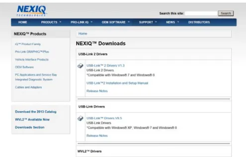
1 On your laptop or PC, navigate to the following website:
www.nexiq.com/downloads
Figure 3.1 NEXIQ™ Downloads
2 From the USB-Link 2 Drivers section, select the latest version of the USB-Link 2 drivers.
3 Carefully read the End User License Agreement.
5 Click on the software title to begin the download. 6 Click on Run (if your browser is Internet Explorer®).
NOTE:
i
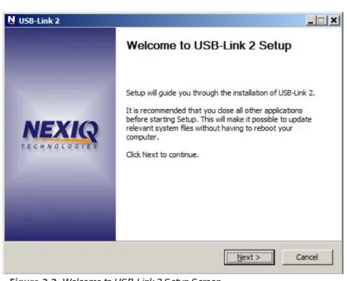
Depending on your Internet browser (for example Google Chrome, or Firefox®), you may have to locate the file (i.e., USB-Link2xxxx.exe) from your Recent Downloads, and then double-click on it to run it.The Welcome to USB-Link 2 Setup screen is displayed.
Figure 3.2 Welcome to USB-Link 2 Setup Screen
7 Carefully read the information displayed on the screen, and follow the recommendations.
- Step 1: Install the Drivers
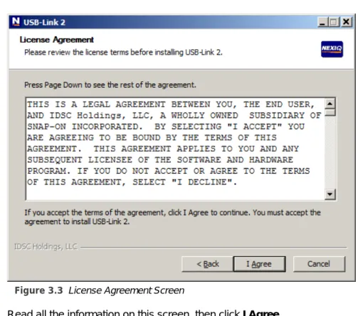
USB-Link™ 2 Wi-Fi Edition Installation and Setup Manual 17 The License Agreement screen is displayed.
Figure 3.3 License Agreement Screen
9 Read all the information on this screen, then click I Agree.
NOTE:
i
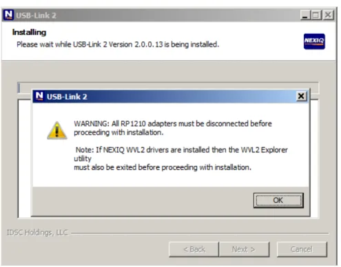
If you do not agree to the terms, click Cancel. A message is displayed prompting you to confirm quitting USB-Link 2 Setup. Click Yes to quit.The following warning message is displayed.
Figure 3.4 Warning Message
10 Carefully read the warning message, and disconnect all RP1210 adapters to which your laptop or PC might be connected prior to proceeding with the installation.
NOTE:
i
You must also exit the WVL2™ Explorer utility if NEXIQ™ WVL2™ drivers have been installed on your laptop or PC.11 Once you have complied with the requirements of the warning message, click
- Step 1: Install the Drivers
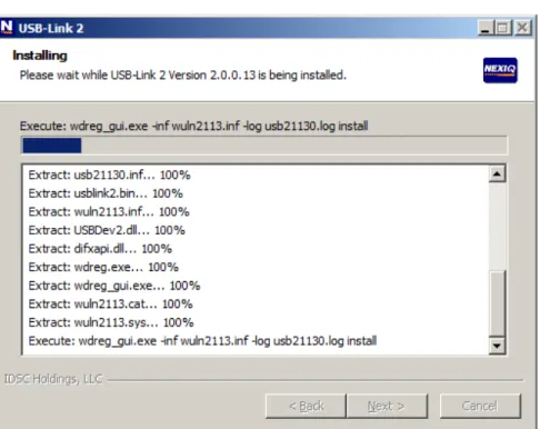
USB-Link™ 2 Wi-Fi Edition Installation and Setup Manual 19 The installation begins and the following screen is displayed.
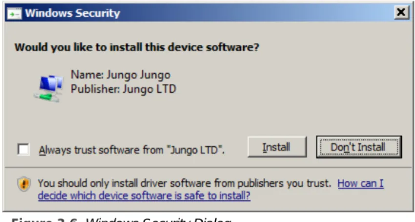
If you are running Windows® 7 or Windows® 8, the following Windows Security dialog may be displayed.
Figure 3.6 Windows Security Dialog
NOTE:
i
You may want to place a check mark in the Always trust software from “Jungo LTD” check box. If you leave it unchecked, this dialog may be dis-played more than once.12 Click Install to continue.
- Step 1: Install the Drivers
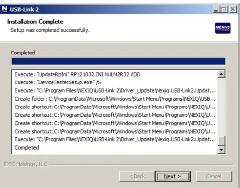
USB-Link™ 2 Wi-Fi Edition Installation and Setup Manual 21 The Installation Complete screen is displayed.
Figure 3.7 Installation Complete Screen
The following completion screen is displayed.
Figure 3.8 Completion Screen
- Step 1: Install the Drivers
USB-Link™ 2 Wi-Fi Edition Installation and Setup Manual 23 The USB-Link™ 2 Explorer utility opens.
Figure 3.9 USB-Link™ 2 Explorer Utility
16 Move on to Step 2: Connect the USB-Link™ 2 to a Vehicle, next in this manual.
Step 2: Connect the USB-Link™ 2 to a Vehicle
Once you have installed the USB-Link™ 2 drivers, you are ready to connect the USB-Link™ 2 to a vehicle using an adapter cable. Any of the following adapters can provide the interface:
• 6-pin Deutsch • 9-pin Deutsch
• 9-pin Deutsch (1 meter) • 6- and 9-pin Deutsch Y • 16-pin J1962 for OBD II
Next, you connect the USB-Link™ 2 to your PC using one of the following options: • Using a USB cable (pg. 24)
• Using Wi-Fi—a wireless local area network (pg. 25)
Connect Using a USB Cable
To connect the USB-Link™ 2 to your PC using a USB cable:
1 Connect the USB cable (i.e., an automotive A to Mini-B USB cable) to the USB port of the PC or laptop.
2 Connect the other end of the cable to the port on the bottom of the device. 3 Connect the DB26 female end of the appropriate adapter cable to the
USB-Link™ 2.
4 Attach the other end of the adapter cable (i.e., the Deutsch connector end) to the vehicle’s diagnostic connector.
NOTE:
i
The vehicle’s diagnostic connector is typically located under the dash-board on the driver’s side, or beside the driver’s seat. It can also be located in the engine compartment, near the electronic control unit (ECU).- Step 2: Connect the USB-Link™ 2 to a Vehicle
USB-Link™ 2 Wi-Fi Edition Installation and Setup Manual 25
Connect Using Wi-Fi
There are two methods for connecting the USB-Link™ 2 to your PC using Wi-Fi: • Infrastructure Mode
• Mini Access Point Mode (peer-to-peer)
NOTE:
i
Because of the numerous configuration variables involved in setting up your network in Infrastructure Mode, please contact your local IT adminis-trator. Our Customer Support specialists cannot assist you in thisendeavor.
Mini Access Point Mode
If you use your PC’s internal wireless network card to connect to your company’s network and the Internet, you may want to obtain an additional wireless network card for use with the USB-Link™ 2. Otherwise when you connect the USB-Link 2 to your PC using Mini Access Point mode, you will not have access to the Internet until you have finished your session and reconnected to your company’s network. To connect the USB-Link™ 2 to your PC using Mini Access Point Mode:
1 Connect the DB26 female end of the appropriate adapter cable to the con-nector on the top of the USB-Link™ 2.
2 Attach the other end of the adapter cable (i.e., the Deutsch connector end) to the vehicle’s diagnostic connector.
NOTE:
i
The vehicle’s diagnostic connector is typically located under the dash-board on the driver’s side, or beside the driver’s seat. It can also be located in the engine compartment, near the electronic control unit (ECU).—At this point, the Power (green) LED on the USB-Link™ 2 should be illu-minated (On).
3 If the Power LED is not illuminated, turn the vehicle’s key to the ON position, leaving the engine Off.
4 Navigate to the System Tray on your PC.
Figure 3.10 Windows® System Tray
5 Click on the Network icon in the System Tray.
Figure 3.11 Network Selection Screen
6 Select the USBLink2_xxx from the list.
NOTE:
i
If the USBLink2 is not displayed, make sure you are connected to the vehi-cle. Also, make sure you are within range (i.e., within 100 ft.). You may need to move your PC closer to the vehicle.Figure 3.12 Selection Highlighted
- Step 2: Connect the USB-Link™ 2 to a Vehicle
USB-Link™ 2 Wi-Fi Edition Installation and Setup Manual 27 The USBLink2.xxx is highlighted.
The connection is made and the device selected is displayed in the USB-Link™ 2 Explorer.
Figure 3.13 USB-Link™ 2 Explorer
NOTE:
i
The USB-Link™ 2 Explorer opened automatically when you installed the USB-Link™ 2 drivers and utilities (see Figure 3.9, on page 23).For more detailed information on using the USB-Link™ 2 Explorer, see
Using the USB-Link™ 2 Explorer on page 32 of this chapter.
You now have a wireless connection to the USB-Link™ 2 and the device is ready for use.
- Step 3: Test the Connection
USB-Link™ 2 Wi-Fi Edition Installation and Setup Manual 29
Step 3: Test the Connection
You use the Device Tester to test the connection between the USB-Link™ 2 and the vehicle. At startup, the Device Tester checks for any NEXIQ™ drivers installed on the PC.
To test the connection between the USB-Link™ 2 and the vehicle:
1 Click Start and then select All Programs
NEXIQ
Device Tester
Device Tester.The application is started and the Device Tester screen is displayed.
Figure 3.14 Device Tester Screen, Showing a Status of Not Connected
2 Use the button in the Device box to select the appropriate device (for example, USB-Link2 WiFi).
—The Device box lists all the devices supported by the NEXIQ drivers in-stalled on the PC.
3 Use the button in the Protocol box to select the appropriate protocol (e.g., J1708, J1939, OBDII, etc.).
—The Protocol box lists only the protocols supported by the device selected in the Device box.
4 Press the Start Test button.
The Device Tester screen is refreshed, and data received from the vehicle bus is displayed in the Bus Messages window.
Figure 3.15 Device Tester Screen, Showing a Status of Connected
NOTE:
i
The Modules Detected window in the lower portion of the screen displays a list of all systems seen on the bus. It is used for J1708 and J1939 only. For all other protocols this window will be unavailable (i.e., NOT USED).- Step 3: Test the Connection
USB-Link™ 2 Wi-Fi Edition Installation and Setup Manual 31 If the Connection Indicator button is red (i.e., Not Connected), do one of the
following:
—For wireless connection using Wi-Fi:
• In the Device list, make sure that the heading is USB-Link 2 WiFi
(Protocol desired).
• Check to ensure that the connections between the USB-Link™ and the vehicle are secure (i.e., the Diagnostic Connector). • Check to make certain that the Power LED on the USB-Link™ is
illuminated.
—For wired connection using a USB cable:
• In the Device list, make sure that the heading is USB-Link2 (Pro-tocol desired).
• Check to ensure that the connections between the USB-Link™ 2 and the PC are secure (i.e., the USB cable).
• Check the connections between the USB-Link™ 2 and the vehi-cle (i.e., the Diagnostic Connector).
• Check to make certain that the Power LED on the USB-Link™ 2 is illuminated.
NOTE:
i
For additional information, refer to “Connect the USB-Link™ to a Vehicle” on page 24 of this manual.Using the USB-Link™ 2 Explorer
The USB-Link™ 2 Explorer utility opened automatically when you installed the USB-Link™ 2 drivers and utilities (see Figure 3.9, on page 23).
To re-open the USB-Link™ 2 Explorer once it has been closed, click on the Show Hidden Icons arrow in your PC’s System Tray.
Figure 3.16 Hidden Icons
Then, double-click on the USB-Link™ 2 icon .
NOTE:
i
You can also access the USB-Link™ 2 Explorer from your PC’s Start menu. Click Start and then select AllPrograms
NEXIQ
USB-Link 2
USB-Link 2 Explorer.- Using the USB-Link™ 2 Explorer
USB-Link™ 2 Wi-Fi Edition Installation and Setup Manual 33 The USB-Link™ 2 Explorer opens.
Figure 3.17 USB-Link™ 2 Explorer
The following menu options are provided: • File (pg. 35)
• Tools (pg. 36)
• Help (pg. 39)
Each menu option includes a number of features. Each of the menu options are discussed in the following sub-sections.
When you click on a USB-Link™ 2 in the list in the left pane, the Configura-tion tab is displayed (Figure 3.18).
The Configuration Tab
The Configuration tab provides the following information: • Device Name and MAC Address
• Wireless Settings
• Internet Protocol (TCP/IP) Settings
This information can be useful when troubleshooting network connection prob-lems. You also use the Configuration tab when switching between the two wireless communication modes:
• Mini Access Point • Infrastructure
To access the Configuration tab:
1 Click on a USB-Link2.xxx in the list in the left pane of the Explorer.
- Using the USB-Link™ 2 Explorer
USB-Link™ 2 Wi-Fi Edition Installation and Setup Manual 35 You can also use the Reset button on the bottom of the USB-Link™ 2 to
switch from Infrastructure Mode back to Mini Access Point Mode (the factory default). Just push and hold the button until all the lights on the front of the device flash, about five (5) seconds.
NOTE:
i
Because of the numerous configuration variables involved in setting up your network in Infrastructure Mode, please contact your local IT administrator.The File Menu
The File menu has one feature, Exit. You use the Exit feature to close the USB-Link™ 2 Explorer.
To exit the USB-Link™ 2 Explorer:
1 Select File from the USB-Link™ 2 Explorer menu bar.
Figure 3.19 Exit Selected
2 Select Exit.
The Tools Menu
The Tools menu provides the following features: • Ping
• Options
Ping
The Ping feature uses the PING protocol to check for the presence of a device on the network.
To check for a device:
1 Select Tools from the USB-Link™ 2 Explorer menu bar. 2 Select Ping.
Figure 3.20 Ping Dialog Box
3 Enter the IP address of the device you want to locate (e.g., 192.168.123.107). 4 Click Start.
The USB-Link™ 2 Explorer searches for the device and, if found, displays the reply.
- Using the USB-Link™ 2 Explorer
USB-Link™ 2 Wi-Fi Edition Installation and Setup Manual 37
Options
The Options feature provides the following features, which are presented as check boxes:
• Start USBLink2 Explorer when Windows starts (pg. 37)
• Show New USBLink2 Notification (pg. 38)
Start USBLink2 Explorer when Windows Starts
You use this feature to manage when the USB-Link™ 2 Explorer opens. The default is to automatically open the USB-Link™ 2 Explorer when Windows starts.
Figure 3.21 Options Menu
To change the default, click on the check box to remove the check mark. Then click OK.
Show New USBLink2 Notification
You use this feature to manage when to display the New USBLink2 notification message box.
Figure 3.22 Notification Box
The default is to display the notification message box whenever a new USB-Link™ 2 is detected.
Figure 3.23 Options Menu
- Using the USB-Link™ 2 Explorer
USB-Link™ 2 Wi-Fi Edition Installation and Setup Manual 39
The Help Menu
The Help menu has one feature, About. You use the About feature to display in-formation about the USB-Link™ 2 Explorer.
To access the Help menu:
1 Select Help from the USB-Link™ 2 Explorer menu bar. 2 Select About.
Figure 3.24 About USB-Link 2 Explorer
3 When you have finished reviewing the information, click OK to close the dialog box.