in cooperation with
In Vehicle Systems and Services (BEG-VS/EEA2)
Master Thesis
Database centric software test management
framework for test metrics
for the fulfillment of the academic degree M.Sc. in Automotive Software Engineering
Submitted by: Parawee Pleehajinda
Matr.-Nr. 326472 February 15, 1989 Bangkok, Thailand
Supervisors: Univ.-Prof. Dr. Wolfram Hardt Dipl.-Ing. (FH) Matthias Schmidt
Parawee Pleehajinda
Database centric software test management framework for test metrics
Master Thesis, Faculty of Computer Science, Department of Computer Engineering Technische Universität Chemnitz, June 2015
Declaration
I hereby declare that this master thesis, topic “Database centric test management framework for test metrics”, is entirely the result of my own work and it has been written by me in its entirety. Also, certify that I elaborated this research independently. The work is based on foundation of the information sources and literatures used in the thesis that I have faithfully and properly cited.
Chemnitz. June 24, 2015 ____________________________ Parawee Pleehajinda
Abstract
Big amounts of test data generated by the current used software testing tools (QA-C/QA-C++ and Cantata) contain a variety of different values. The variances cause enormous challenges in data aggregation and interpretation that directly affect generation of test metrics. Due to the circumstance of data processing, this master thesis introduces a database-centric test management framework for test metrics aims at centrally handling the big data as well as facilitating the generation of test metrics. Each test result will be individually parsed to be a particular format before being stored in a centralized database. A friendly front-end user interface is connected and synchronized with the database that allows authorized users to interact with the stored data. With a granularity tracking mechanism, any stored data will be systematically located and programmatically interpreted by a test metrics generator to create various kinds of high-quality test metrics. The automatization of the framework is driven by Jenkins CI to automatically and periodically performing the sequential operations. The technology greatly and effectively optimizes and reduces effort in the development, as well as enhance the performance of the software testing processes. In this research, the framework is only started at managing the testing processes on software-unit level. However, because of the independence of the database from levels of software testing, it could also be expanded to support software development at any level.
Keywords – software testing, test management framework, test data, software testing tools, test metrics, database-centric, data aggregation and interpretation, automatization.
Acknowledgement
I would like to express the deepest appreciation to my professor Univ.-Prof. Dr. Wolfram Hardt and advisor Dr. Ariane Heller for their kindly patience, motivation, and knowledge and continuous support in my master study and research. The guidance suggested by them helped me in all the time of research and writing of this thesis.
Besides my professor and advisor, I would like to thank the rest of my thesis committee: Dr. Mirko Caspar and Dipl.-Inf. Norbert Englisch for their encouragement, insightful guidance and questions during my study and research.
My sincere thanks also goes to the department In Vehicle Systems and Services, Bosch Engineering GmbH, the mentor Dipl.-Ing. (FH) Matthias Schmidt and all of colleagues at BEG-VS/EEA2 for offering me the master internship and continuously master thesis opportunities in their teams and leading me working on diverse exciting developments.
Last but not the least, I would like to express sincere gratitude to my parents: Asst. Prof. Suchin Pleehajinda and Mrs. Tipbha Pleehajinda for giving birth to me and spiritually supporting me in every step throughout my life.
Table of Contents
Declaration I Abstract II
Acknowledgement III
List of figures VII List of tables IX Abbreviations X 1 Introduction 1 1.1 Motivation . . . 1 1.2 Scientific challenges . . . 2 1.3 Thesis structure . . . 6 2 Research 8 2.1 Collaborative framework . . . 8 2.1.1 Process integration . . . 9 2.1.2 Framework environment . . . 10
2.2 Database in software engineering . . . 14
2.2.1 Major properties of databases . . . 14
2.2.2 Requirements of database systems . . . 16
2.2.3 Challenges in database technology . . . 18
2.3 Database models . . . 20
2.3.1 Relational model . . . 20
2.3.2 Object model . . . 26
2.3.3 Object-relation model . . . 31
2.4 Database systems . . . 36
2.4.1 Database system hardware . . . 36
2.4.2 Database system software . . . 37
2.4.3 Database system users . . . 40
2.4.4 Database system architecture . . . 41
2.4.5 Database management systems . . . 44
2.5.1 Automatization in software development . . . 47
2.5.2 Interface of system components . . . 49
2.5.3 Automatization management . . . 51
3 Discussion 53
3.1 Framework conceptualization . . . 53
3.2 Definition of collaboration . . . 57
3.3 Database model selection . . . 60
3.3.1 Comparison of alternative models . . . 60
3.3.2 Compromising database models . . . 62
3.4 Database system selection . . . 63
3.4.1 Comparison of alternative database systems . . . 63
3.4.2 Compromising database management systems . . . 64
3.5 Development tools selection . . . 65
3.5.1 Environment of the database . . . 65
3.5.2 Environment of raw data parsers . . . 66
3.5.3 Environment of front-end user interface . . . 66
3.5.4 Environment of test metrics generator . . . 67
3.5.5 Summarization of the environment . . . 67
4 Implementation 69
4.1 Environmental setup . . . 69
4.2 Development of the database . . . 73
4.2.1 Setting up a database using PostgreSQL 9.3 . . . 73
4.2.2 Implementing the database structure . . . 75
4.3 Development of raw data parsers . . . 80
4.3.1 Developing programming parsers . . . 80
4.3.2 Transferring parsed data to the database . . . 81
4.4 Development of metrics generator . . . 83
4.4.1 Generating metrics in PNG format . . . 83
4.4.2 Generating metrics in CSV format . . . 84
4.5 Development of user interface . . . 85
4.5.1 Generating the front-end user interface . . . 85
4.6 Automate the framework . . . 90 5 Conclusion 93 5.1 Development summary . . . 93 5.2 Future research . . . 96 6 References 98 7 Appendices 102
Appendix A – Evolution of database systems A.1 Evolution timeline . . . 102
A.2 Benefits of the evolution . . . 104
Appendix B – Programming diagrams B.1 Programming dependency . . . 107
B.2 Database middle interface . . . 108
B.3 Data synchronizer . . . 109
B.4 Database updater . . . 110
B.5 Interface updater . . . 111
Appendix C – Programming codes C.1 SQL statements to create user-defined types . . . 112
C.2 SQL statements to inherit existing tables . . . 113
C.3 Python functions as the Database API . . . 114
C.4 Python functions as raw data parsers . . . 115
C.5 Python function to insert data to the database . . . 116
C.6 Python with Matplotlib to generate graphic metrics . . . 117
List of Figures
1.1 Current framework of software unit testing . . . 2
1.2 Researching database-centric software testing management . . . 5
2.1 Fundamental integration concepts . . . 9
2.2 Relationship in a database system . . . 18
2.3 Relationship types in relational database model . . . 21
2.4 Relationship of primary key and foreign key . . . 23
2.5 An operator created by a user-defined type . . . 26
2.6 Inheritance of an existing data object in object model . . . 27
2.7 Encapsulation of a data object in object model . . . 28
2.8 Realization of polymorphism in object model . . . 29
2.9 Object-relational impedance mismatch in data representation . . . 32
2.10 Transition states in database transaction . . . 38
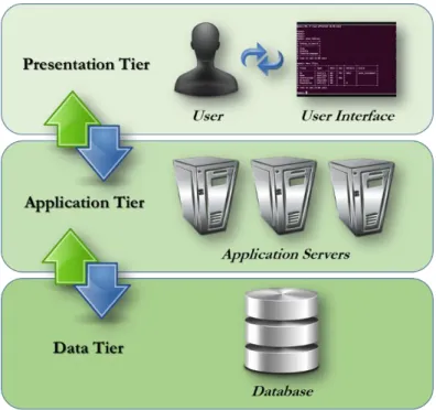
2.11 Functional architecture of DBMSs . . . 41
2.12 Architecture of three-tier database systems . . . 43
2.13 An overview of typical database management systems . . . 45
2.14 Alternative approaches of system interface . . . 49
2.15 Pipelining execution as a basis of continuous integration . . . 51
3.1 An overview of conceptual framework . . . 53
3.2 An overview process of raw data parsing using decentralized parsers . . . 54
3.3 An overview process of generating a user interface using Microsoft Excel . . . 55
3.4 An overview process of interpreting data though a centralized interface . . . 55
3.5 An overview process of manipulating data though database interface . . . 56
4.1 The concrete structure of development workspace . . . 70
4.2 The global configuration file used in administrating the framework . . . 71
4.3 The data object model used in handling data in object-oriented way . . . 71
4.4 Selecting the locale of PostgreSQL to support European characters . . . 73
4.5 A new database created for development of the framework . . . 74
4.6 The structure of database implemented using user-defined types . . . 76
4.7 The structured directories used to store raw test data . . . 80
4.9 The processes of transferring parsed data to database . . . 82
4.10 Graphics generated by the metrics generator using Matplotlib . . . 83
4.11 Plain-text metrics generated in CSV format . . . 84
4.12 The object-oriented structure used in handling queried data . . . 86
4.13 Flow diagram of data synchronization . . . 88
4.14 The realization of security mechanism embedded in the user interface . . . 89
4.15 Sequential execution flow driven by Jenkins CI . . . 90
4.16 The implemented framework controlled by Jenkins CI . . . 91
4.17 The configuration of software testing processes in Jenkins CI . . . 92
5.1 A future framework expanded to support various applications . . . 96
1
List of Tables
2.1 Comparison of decentralized and centralized interface approaches . . . 50
3.1 Definition of the framework based on three-tier architecture . . . 58
3.2 Comparison of alternative database models . . . 61
3.3 Comparison of alternative database management systems . . . 63
3.4 Alternative PostgreSQL-API driven by Python . . . 65
3.5 Alternative Python packages for Microsoft Excel . . . 66
3.6 Development tools for framework development . . . 68
4.1 Descriptions of class attributes defined in data object model . . . 72
Abbreviations
ACID Atomicity Consistency Isolation Durability ANSI American National Standard Institute API Application Programming Interface
ASCII American Standard Code for Information Interchange ASIL Automotive Safety Integrity Level
BSD Berkley Software Distribution CI Continuous Integration
CMS Configuration Management System CRUD Create Read Update Delete
CSV Comma-Separated Values DBMS Database Management System
DOM Data Object Model
FK Foreign Key
GUI Graphic User Interface LGPL Lesser General Public License
OODBMS Object-Oriented Database Management System OQL Object Query Language
ORDBMS Object-Relational Database Management System
PK Primary Key
PNG Portable Network Graphics
QM Quality Managed
RAM Random Access Memory
RDBMS Relational Database Management System
ROM Read-Only Memory
SQL Structured Query Language SVN Sub Version Control SWUT Software Unit Testing
Introduction
1.1
Motivation
Development of embedded systems in automotive industry is rapidly and continuously advancing both in hardware and software. A high complexity of development is evoked in every phase throughout the lifetime. Several development processes become more complicated, e.g. the initialization of the project, general operations, testing processes or the finalization of the project. In this circumstance, the completeness of each operation must be strictly ensured and validated. One of the essential processes that directly indicates the correctness and quality is testing which is involved in several phases throughout the development, e.g. reviewing, testing, integrating, etc. In software development, an effective software testing yields a high quality of the development. It greatly facilitates developers in identifying progress and potentially risks or bugs arising during the development. Since any issue can be quickly detected, the developers will be able to handle it effectively and accurately steer the development into the right way. Thus, software testing should be considered, placed, and performed during the development as early and regularly as possible. Therefore, in consequence, the continuous of the activity will hugely generate a variety of big data. Those artifacts will be separately stored in different locations before being dynamically transferred and processed in further operations. The decentralization and untracking of the stored data directly affect several processes of data aggregation and interpretation. Hence, without an effective big data handling mechanism, many related processes, e.g. data tracking, test metrics generation, etc., can be severely impaired and consequently degrade the quality of the development.
Furthermore, when software is being developed, any result and movement of every on-going phase must be assessed and visualized regularly through test metrics. The metrics are the essential keys for measurement that provide developers intuitive methods for progressive estimation and issue identification in any state of the development. As previously mentioned, the lack of big data handling mechanism will directly affect the processes of data aggregation and interpretation and causes enormous challenges in generating various kinds of test metrics.
1.2
Scientific Challenges
Although several tools for big data handling are available in software markets nowadays and used broadly in organizations to manage their essential data, but those are still not fully integrated and driven as a single collaborative system. In this case, the system with a high capability of data management that effectively supports the amounts of data is required, especially to facilitate a process of various test metrics generation in software development.
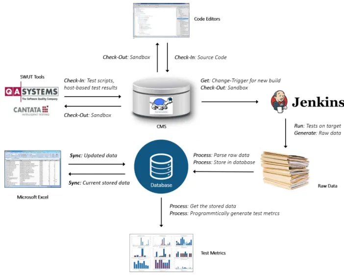
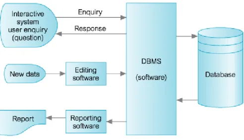
In the current software testing framework, illustrated by figure 1.1, each existing SWUT tool is responsible to analyze and perform software testing. In the areas of this research, the software testing is only based on software-unit level. Each software unit will be tested by the tools before getting results, i.e. QA-C/QA-C++ are applications used for static code analysis, and Cantata is mainly used for dynamic code analysis. Microsoft Excel is used to collect and summarize the data gathered from the testing activities by using the built-in features to generate graphics and metrics.
Figure 1.1: Current framework of software unit testing.
In the CMS, TortoiseSVN is used to handle each version of development artifacts. After a stored release has been checked out into a sandbox, it will be prompt to be transferred to code editors
and the used tools. Anyway, at the current, after finished a testing process, a large volume of complicate raw data, e.g. processors, subsystems, atomic components, test scripts and results, etc., will be hugely produced. It causes several challenges in data handling, especially in generating test metrics that requires several related data to be interpreted.
Decentralization of development artifacts
Due to a huge increase in development complexity of embedded system, a software or hardware component may be repeatedly used in several developing units involved in different platforms. For instance, a single project may contain multiple processors produced by different suppliers. Each of developing unit may be under control of several responsible developers, or even integrated to other systems. In this situation, the lack of co-relation of development artifacts significantly leads the software testing processes more complex.
At the current, test results of each sourcefile is separately stored in several directories in the CMS. By storing the artifacts in spread locations, the data will be stored without having any relation with others related artifacts. Due to the decentralization, any further process that requires those artifacts will not be effectively performed. The current framework becomes more complicated since huge amounts of data are stored in this manner. Thus, in practice, processes or developers that require the stored data for any further operation need to check the scratched data out from the CMS to their local workspaces, then manually categorize and summarize the data as desired.
Transformation of raw data
After a software testing activity finished, a big data of development artifacts, e.g. test scripts and test results, will be generated and sequentially conveyed to the CMS after being checked in. Those generated artifacts are fully raw that cannot be simply used in data processing. Thus, before being processed in further operations, the data that currently contain different values must be transformed into a particular format first in order to unify the variances.
As previously mentioned, several current SWUT tools currently generate huge amounts of data in various formats and contents depending on the configurations specified in the CMS. Hence, a transformation of the raw data will be an essential process that parses the data to be usable and understandable artifacts that can be effective used by any participating data-related operations.
Complexity in test metrics generation
As maintaining each version of development artifacts using the CMS as well as the impact of the decentralization, a process of metrics generation is slightly ineffective. Creating metrics to visualize the development in a specific period of time requires an effective integration of the stored data. Without the integration, the process may consume a huge effort to capture the required data that takes several high-cost processes.
The process of generating metrics should be simply performed. That means, the framework must be able to simply and effectively retrieve any needed stored development artifacts to generate test metrics. The simplicity can beneficially help to reduce effort in processing the uncategorized artifacts as well as result in a high quality of metrics.
Furthermore, instead of generating development metrics using provided tools of the Microsoft Excel, programming scripts can be alternatively used to automatically and programmatically interpret the data and transform into various kinds of metrics.
Project-independent framework
The use of a database-centric architecture in handling big data is one of the popular approaches that greatly accounts to the challenging situation that helps in maintaining every version of data securely and effectively.
Therefore, several points of engineering must considered before implementing the architecture. Those points of challenge entail all components in the researching framework, e.g. structure of the database, operating engines, system interfaces, automatization of the framework, etc. Furthermore, the developed framework must be fully independent from used SWUT tools or projects. The independence will globally support any level of software development to handle a huge amount of data continuously generated by testing activities and facilitate a generation of metrics.
The figure 1.2 presents the areas of this research to account all of the scientific challenges in managing software testing processes and test metric generation based on the current framework showing in the previous figure:
Figure 1.2: Researching database-centric software test management framework for test metrics.
The researching framework aims to partially transform and extend the capability of the current one that becomes more complicated due to a lack data aggregation and interpretation. The database-centric architecture will be researched and implemented using a centralized database to electronically store test data in software testing. Various kinds of test metrics will be programmatically generated to help developers in visualizing the development as well as optimizing efforts. A worksheet of Microsoft Excel will be developed to be a friendly channel for authorized users to interact with the data stored in the database. Furthermore, an automatization of the framework will also be realized to support the development in automatically and periodically executing any task or operation.
1.3
Thesis Structure
Before the implementation of the database-centric software test management framework for test metrics could be started, an intensive study had been necessary. The study involved the relevant modules, the collaborative components, and the alternative approaches. This document will present the knowledge collected while studying the former framework of software testing. Also discusses the principles used to enhance the capability in test data handling, especially to automatically generate various kinds of test metrics.
Chapter 1
The introduction presents an overview of the existing software testing framework. It expresses the motivations that initiate this research, as well as determines the problem statements. A number of scientific challenges is explained. The goals of this research that are mainly emphasized in developing a collaborative framework to generate high-quality test metrics is also addressed.
Chapter 2
The chapter presents the research of the formal collaborative framework used in software engineering. It presents the relationships of all related component that are used to build up a complex integrated platform. The research covers studying of roles of database systems participating in software development. The evolution of database systems since the first system had been introduced is summarized. It gives a detailed research of several alternative database models and famous DBMS. The internal mechanisms of the systems necessary in driving the framework are explained. Furthermore, a deep study about the framework automatization, based on Jenkins CI, is also introduced in this section to present a number of potential approaches that can be used to operate the system in automatic.
Chapter 3
Detailed discussions of the alternative approaches, tools and environments is placed. As explained about the essential components in a collaborative framework in previous section, each of them will be considered and selected. The conceptual development is formed up and intuitively illustrated in form of specification and realization comparisons. Thus, the framework will be completely conceptualized and concluded in the part.
Chapter 4
The implementation and realization of the researched theoretical approaches are held in this chapter. Each programming part to build up framework is also detailed. This part will not present only the implementations of relative components, but also the interfaces and integrations of each developed modules that implement the selected approaches. Especially, the implementation of a mechanism that programmatically generates various kinds of test metrics which is one of the major parts of this research.
Chapter 5
This chapter gives a summarization of the whole development by concluding each step of the research, discussions, and implementations. As well as presenting an idea of future research in order to extend the capability to support other levels of software development.
In conclusion, as the structure of this document, the research will be presented by starting at identifying the scientific challenges that motivate the master thesis. Several alternative theoretical approaches are discussed before being selected to be used in the development. Implementations of the chosen approaches will be precisely explained. Furthermore, a number of possible additional researches in future is also introduced at the end of the document.
Chapter 2
Research
2.1
Collaborative Framework
In the last decades, there has been a major change in the way project development entities interact with their connecting applications and each other. The spread collaborative modules that are responsible to process their own tasks may away from centralized developing site, e.g. software testing tools may stand separately away from centralized data repository regarding to this master thesis. A new paradigm of distributed project engineering was emerged in order to hugely enhance the flexibility of the development chains as well as initiating customized solutions based on consumer demand.
The key to achieving flexibility, efficiency, and responsiveness is data that is available to serve the right data and ready to be accessed by the right person at the right time. In project development, to be able to capture and deliver the right data, modern developments are consuming data management technologies at ever increasing rates1. And each of these technologies improves the precise capture, and flow of data management, as well as automated delivery of the data that enables some activities in the development to function more effectively.
Therefore, to achieve agility across the engineering goals, data must be manipulated seamlessly and effectively from application to application without loss or corruption. The manipulation entails flowing from the software testing tools that generate a huge amount of software test results to the system that centrally store development data, and later delivery to the metric generator to generate various kinds of desired metrics used for development assessment, as well as transferring the data to developers or customers in different sites of working area.
In software engineering, the basis of collaborative operation greatly helps in improvement in the capabilities and performance of the project development, especially in term of exchanging of increasingly complex data continuously generated during the time.
2.1.1 Process integration
Typically, “integration” is the engineering and management process that creates or improves flows between collaborative processes designed for different purposes. What actually flows between the systems is data. As mentioned, the most critical to every phase of the project development is that all of the right data flows in the right ways among the processes, as well as the people who interact it, to interpret the data correctly.
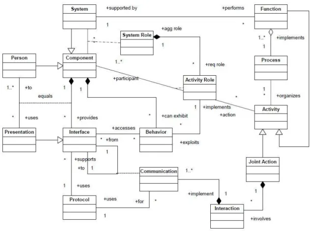
Process integration aims to investigate relationships to produce classifications and merge activities into a standardized system. Integration is the process of merging elements from 2 similar antecedent processes to create a single process that can be used to replace the original processes.2. Figure 2.1 represents a static structure diagram formulated in UML3, showing the relationships among the principal concepts defined in this section:
Figure 2.1: Fundamental integration concepts.
2 Ct. [MORRISON et al. 2009] pp 3. 3 Ct. [BARKMEYER et al. 2003] pp. 3.
2.1.2 Framework environment
In a view of system integration, referring to the figure, this section presents detailed definitions of the fundamental concepts for systems integration and the terms used to describe them in order to build up collaborative framework, in the context of this research, that are capable of centralizing and integrating data generated by different sources, as well as jointly participating in accomplishing the major goals of aggregation and interpretation of software development data, as follows:
System
A complex and pre-designed combination of a number of sub modules of software, hardware, resources, or even humans to accomplish either general or specific functions. In order to specify the structure of the system, a process of system design is performed. The process includes several view of system captures, i.e. the component view, the information view, and the computational process view4.
Furthermore, the system functionality can be broken down into several sequences to illustrate its collaborative functions corresponding to each component subsystems. To accomplish the designing of the system, a specification for each granularity must also be available in order to initiate interfaces of the system.
Component5
A subsystem of the higher-level system that provides some or all of its functions as sub functions. In this context, a component is a member of the framework which is an application connecting and interacting to each other among the framework.
Integration
A state of a set of components or agents, as previously mentioned, that enables them to act jointly in one or more sub-functions of a function of a larger system.
To be precise, integration is also one of the essential systems engineering processes of design and development consisting a number of operations, i.e. identification of joining operation of 2 or
4Ct. [BARKMEYER et al. 2003] pp. 3. 5 Might be called “Agents” in other literatures.
more independent agents in order to enable particular communications to enhance the functionality of the larger system, an operation of role assignment in functions of the larger system to nominal resources, determination of the suitability of specific resources to fulfill those roles, the configuration or modification of the resources to enable them to perform those roles, and the creation or acquisition of additional resources where needed6.
In this context, process of integration is taken mainly at the center of the framework to join each independent applications, e.g. software testing tools, parsers of test results, metric generator, etc., to the central repository. As mentioned, the integration results in improvements of the larger view of the system. That means, the functionality of the entire framework is enhanced by the integration.
Behavior
The activities of a single component, what the system or component exactly and precisely performs. Typically, a behavior is visualized by various means of system measurement through measurable attributes of the component itself. Therefore, technically, the behavior of any component or even the entire system can also be influenced by environmental conditions, past actions, or configuration.
Function
As previously mentioned, activities of a component is realized as several parts of behavior, called function, which satisfies the specific purpose of the activities. Technically, a function is modeled as a subset of state transitions corresponding to the purpose of the system. Precisely, terms of behavior and function are closely related which both of them are modeled in different views of system perspective.
Resource
In any execution of a function, the system may require several collaborative components or information set, called resources, to perform execution in order to accomplish the expect results. The resources can be classified active resource or actor which is a resource that performs one or more functions, e.g. manpower or person, devices, etc., to makes decisions of one or more function. On the other hand, a passive resource is used by active resources in the performance of
a function. In this context, numbers of passive resource can be referred to the resources that are used to represent the raw data or any static system component that is indirectly used in a function7. Process
A process is typically used to represent a sequence of collaborative procedures that are linked to build up intended activities in order to achieve any expected results. Process is basically classified using level of human involvement in initiation or execution, i.e. automated process which is a process that is executed without any intervention of human, semi-automated or computer-assisted process that is executed with a partial support of human, and manual process that is fully executed with intervention of human or human or human-intelligence.
Role
In system collaboration, a role is basically characterized by desired behaviors. A role is used to characterize a resource to imply its ability in order to exhibit those behaviors. As illustrated in the figure, a role can be classified in either activity or system role, as follows:
Activity role: The participation of a nominal resource in the activity, in level of function and realized component behaviors.
System role: In system level, the role broadly involves a set of all activity roles processing and using resource supported by the system.
Joint action
The action entails all participations of collaborated resources in accomplishing a single function, e.g. coordination, collaboration, cooperation, etc. The action involves interactions among the resources in order to jointly establish communication on the part of each actor in either activity level or system level.
Communication
Technically, one actor may communicate with another for the purpose of obtaining specific behaviors of the other party that are relevant to a function the actor is performing, as well as obtaining specific behaviors from either or both communicating actors. The operation is said to
be an activity of exchanging data between actors resulting a flow of information establishing from one actor to another.
The flow broadly refers to any process of process mechanisms, e.g. rendering and transmitting of internal information, and, vice versa, interpretation of received data into internal information8. Protocol
Any communication must be established by precisely constructed higher-level abstraction of communication, called protocol, to initiate a way in which information flows between participating resources.
Interface and Presentation
Interactive channels allow user or even interacting parties to communicate with internal system as well as interacting with any possible interactive internal components. In the context of this thesis, the interface is emphasized in interaction between incoming parsed software data and outcomes of interpretation of the stored data in repository displaying on interface in various forms of presentation.
In summary, a systems integration is an engineering process for constructing systems. One of the first questions that arises is: What is meant by “automating systems integration”? And in order to answer that question, it is necessary to introduce and define a larger set of terms at first based on the mentioned essential fundamental system components.
8 Ct. [BARKMEYER et al. 2003] pp. 5.
2.2
Database in Software Engineering
Software engineering is an application of complex processes involving a variety of collaborative tasks driven by software development teams to develop numbers of methods and products on the various production phases. Huge amounts of developed objects and units of information generate challenges of the development that require an appropriate tools to persistently store them as well as effectively manage the archiving system to meet the expected goals of development.
Database technology has provided a variety of possible solutions that exactly address the challenges since the first database system was introduced in over the past 30 years9. Nowadays, numbers of database management systems are used widely with a capability of extending the range of application integration to support various business requirements. Obviously, the wide-range integration indicates that database technology and software engineering are related in several collaborative ways and support each other to appropriate services to the requesting processes.
2.2.1 Major properties of databases
A database is a set of interrelated data which a known data can be stored with a structured relationship. Various properties of a database beneficially help in the entire process of software engineering, e.g. a database represents a structure of real development structure which is a logically coherent set of potentially huge amounts of data with concrete implicit or explicit meaning to facilitate development lifecycle to achieve expected goals whether in quality aspect or data consistency and integrity as well as maintain security of the stored data, the independence of data offers effective mechanism of manipulations of the stored data that can be operated independently as well as accessing database can also be simply operated over a user-friendly and flexible interaction channels which maximizes the operation performance of users.
Database technology constitutes modeling of real-world aspects of software development by comprising concepts and system methods for a construction and an operation of the software system which definitely are essential parts to lead the software development to success as well as response demands of the organization and desired achievements of the development. The
9 Ct. [DITTRICH et al. 2000] pp. 1.
important properties of database system, that are essential for developing any secure and effective systems, are discussed as follows10:
Data integrity
Mechanisms to control semantic integrity in order to ensure the consistency of the stored data during its manipulation are provided in a manner of data constraints. The automatic detection mechanism greatly helps in checking the correctness of configurations and implementation.
Data persistence
Once a data object has been persistently recorded in a database, its life spans beyond the execution time allowing it to be manipulated anytime. This manner corresponds to a goal of software engineering in order to develop a system object that can be reused by other processes within or even across the different system environments.
Data security
Any malicious or accidental access can be detected and protected by security mechanisms to prevent access by unauthorized users. User privilege and rules can be constructed in database configuration to grant rights to known users to access any authorized part of the database.
Data querying
Stored data can be retrieved by users or even through programming by specifying a user-defined condition or criteria. The querying can be simply performed over the system interface using a declarative query specification with a relationship among the specified data. Various standard query languages have been developed and commonly used nowadays including Structured Query Language (SQL) for relational database, and Object Query Language (OQL) used in object-oriented database.
In fact, each database management system also provides specific features to support the specific purposes of software development. Therefore, the general purpose of all systems is to manage huge amounts of system data in a consistent manner as well as providing comfortable and effective
mechanisms of data manipulation in the database. The context of database system is currently stated an integration of a database and database management software which mainly provides more functionality to facilitate every individual task of software engineering.
2.2.2 Requirements of database systems
Databases are used as the data interconnection as integration medium to be central interfaces of various applications and subsystems. Several functional and operational requirements are generated aimed at exploring effective solutions to support more complex archiving models of software engineering environment to handle huge amounts of system artifacts which are system or human generated data objects, e.g. diagrams, programming codes, executable objects, test data, or human-readable documents. The engineering requirements of databases for software engineering are discussed following:
Persistent repository of artifacts
The data model of a database must be able to store different kinds of artifacts as well as allowing the database schema including the description of potentially required artifact type and the defined artifact descriptions to be dynamically evolved during the lifetime to support a variety of artifacts.
Artifact integrity and consistency
The integrity and consistency of the stored data are driven by the mechanism of static constraints in order to validate any state of artifacts in the system while dynamic constraints maintain an integrity and consistency of state transition and development history over time. The mechanisms provide a strong and secure system in order to main the integrity and consistency of the stored data that users are able to operate system without being aware of any state of individual stored data elements in the system.
Artifact retrieval
The techniques of data retrieval depend on the implemented data model in the database system. Therefore, as using a database in business allows every stored artifacts can be recalled and reused anytime in a manner of reusable software libraries which is a prerequisite for software engineering to enhance the capability of the system to handle any demand on manipulating data.
Artifact configuration management
During the lifetime, numbers of artifacts generated in execution states and reflect progress of development. Various versions of the artifacts as well as the relationships among the artifacts at each state must be stored to effectively support software development.
In complex software system, the file-based mechanism to operate versioning of system artifacts is called software configuration management which provides functionality of system artifact management to support the versioning of a granularity of system artifact. Therefore, the database must be able to support a customization of version management granularity as well in order to maximize the flexibility of the artifact storage system.
System integration
In software engineering environment, aka. SEE, the integration of collaborative development tools is important, e.g. a data artifact generated by one tool must be usable by other tools in the environment. The requirement can be achieved by constructing a common interface to access the infrastructure to facilitate interconnection of the tools and provide services to each other.
Evaluation of development metrics
Assessing software development using software metrics has been considered for several years. Various kind of metrics are used to effectively assess progress of development throughout the lifecycle as well as identifying issues occurring during the development. Thus, the requirement is emphasized on the capability of the database that must be able to collect and persistently store any specific data used to generate metrics to provide possibility of subsequent evaluation in any point of time during the development timeline.
As mentioned above, the requirements are mainly based on ease and effectiveness of data manipulation in a way that securely and correctly maintain the characteristics as well as the correctness of the affected data. Furthermore, the database systems must also be able to serve a possibility to any additional process in term of data and process interaction to establish a dynamic connection in processing the stored data with minimal limitations. If the requirements are taken into account, any database system will be able to grow up as a versatile and more powerful collaborative system that greatly responses the needs of organization.
2.2.3 Challenges in database technology
In recent years, several database approaches have been introduced and used to develop powerful and appropriate file storing systems. In fact, each approach provides several advantages and also disadvantages depending on the development environment as well as applications which it is integrated with. Various special-purpose systems have been developed to response demands of specific business purposes as well as satisfy requirements of database system. The systems are based on the principle of supporting versioning of development artifact as well as extending in data and transaction models to extend the functionality of the system.
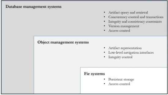
Meanwhile, several general-purpose database systems have also built up to support a wide range of extending of big data and mainly to support effective modeling of software artifact, software configuration management, dynamically evolving of development and cooperative transactions. Up to this point, obviously, one database system whether it is developed for special or general purposes, it is definitely based on the common infrastructure with common basic mechanisms. A system is commonly comprised of a relationship of multi-level subsystems, i.e. file systems at the lowest, object management systems, and database management systems at higher levels respectively, described as the figure 2.211.
Figure 2.2: Relationship in a database system.
11 Ct. [DITTRICH et al. 2000] pp. 6.
Software engineering is a term of application dealing with non-tangible products which can be widely evolved over time or even manipulated across different platforms or organizations. Since an appropriate approach has been implemented in database, the further considerations in several aspects must be evaluated.
In order to optimize the infrastructure, the use of system resources must be minimized together with a functionality of the system allowing components to be accessed across different environments from different software engineering organizations as well as providing mechanisms to share the persistent stored artifacts transparently to optimize computational resources by operating sharing artifacts thought a common interface which can also be connected to a variety of interconnected tools as needed without being aware of physical infrastructure.
Furthermore, a mechanism that retrieves the stored data objects which is one of the major functionalities of database systems must focus on aspects of data integrity and security by providing a powerful mechanism of fault detection and tolerance to the system. Since the functional and operational requirements have been identified and responded effectively, database systems with high data storing technology are now enough to be implemented in general purposes of a wide-range interconnected business applications12.
12 Ct. [TARR/CLARKE 1993] pp. 1-2.
2.3
Database Models
In database systems, a data model is used to explicitly specifying the data structure of a database in which each data element associates one another as well as providing the definition, format, and relationship among the data to realize the aims of a business. A model is a realization of a formalization and documentation of existing or ideal events and processes interpreted during the system design phase to visualize and translate complex system specifications and technical requirements into a precise and understandable representation of event and process flows. The representation is generally generated as formal diagrams or flowcharts to illustrate the relationship between data elements and also ensures all of the specifications and requirements have been identified and structured.
Basically, a data model is used only to analyze the requirements of a business mainly emphasizes in generating system representations and visualizing operating framework. Database modeling which is an operation of interpreting the realized representations will be constructed after the conclusion of data modeling takes place to formalize a logical structure and also implement the relationship among the system elements by forming a linkage between each data element to one another. Since a data model has been generated, a database model will be selected to implement the system of the data model as well as used to determine how the system is structured and specifies the manner of data manipulation with a relationship between each part of data13.
In system development, there is a number of database models to implement a database system. This research focuses only on following common logical data models presented in the figure 2.2, in previous section, which are widely used in businesses nowadays.
2.3.1 Relational model
A relational model is based on a collective set of multiple data sets represented in a tabular form consists of general model components14, i.e. tables, records and columns to establish a concrete-defined relationship among database tables and components. Relationships of components to establish communication between tables and also allows every component to share information
13 Ct. [BALLARD 1998] pp. 1-17. 14 Ct. [STAJANO 1998] pp. 6.
between each other that facilitates data searchability, organization and reporting when performing system analysis using mathematical techniques15.
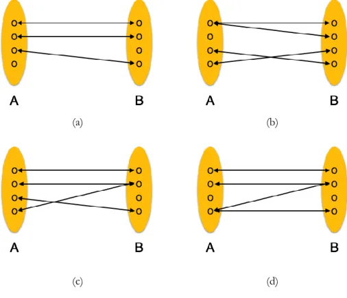
The relational model organizes data in several different ways. A table contains numbers of record which each record is identified by a unique data instance. Each table has its internal relation to identify each table columns. In database systems, there is a number of data relationships used in real systems to establish linkages of every data elements stored in database, in figure 2.3:
(a) (b)
(c) (d)
Figure 2.3: Relationship types in relational database model.
Each relationship defines a specific manner of the linkages amount tables in database that provides different advantages and functionalities in database organization, as follows:
One-to-one
In figure 2.3(a), the relationship refers to relationships of 2 items which one is able to only relate to another one. In a meaning of database, means one table record exactly relates to another record in another table.
One-to-many
In figure 2.3(b), the relationship allows frequently mapping of items which one is stored in one place and referenced by multiple other items. In a meaning of database, means one table record has relationship with many records in another table.
Many-to-one
In figure 2.3(c), the relationship is a vice versa of the one-to-many relationship. It mainly presents the mapping of the side of multiple of items that referenced by a single item, whereas the one-to-many focuses on the side of a single item. In a meaning of database, means one or more than one table record relates to a single record in another table.
Many-to-many
In figure 2.3(d), the relationship is placed among more than one item which relates to multiple items in another place. In database term, means one or more table record can be related to multiple records in another table.
In data organizing, the database system generates a new unique value every time when a new data record is written to the table, the unique value is called PK. The primary key is used by the system primarily for accessing the table to uniquely identify a single data record in a table. At least one column of a table must be specified and registered to be the primary key of the table16.
Whereas the primary keys are used to uniquely identify a data record in a table referenced by other tables in the system, another important key of the system which is used to reference a data record of another table is called an FK. A table which has a foreign key referencing to another table is called “referencing or child table” and a table which its primary key is referenced by the foreign key is called “referenced or parent table”. The relationship of the primary key and foreign key is demonstrated as the following.
16 Ct. [BALTER 2007]
Figure 2.4: Relationship of primary key and foreign key.
The figure presents a relationship between the primary key of table “Product” which is referenced by a foreign key in table “Component” that uniquely identifies a data record of the referenced table. If the value of the referenced key is updated, the meaning of the referencing table will also be automatically modified. Thus, developer is highly responsible to handle those keys securely. In practice, there is also a possibility, provided by the relational model to support the reality of real-world database implementation in organizations, that the primary key can be composed of a combination of multiple columns in a table in case of a unique data record must be identified by a set of columns e.g. a unique product model must be identified by the product name together with a revision or build number, or a car must be identified by its brand model name.
The relational database model greatly provides several advantages in developing database systems. These following characteristics of this model also serve the major benefits to developers as well as users in various point of views in software engineering:
Ease of use
A set of collaborative components consisting tables with a number of rows and columns representing in tabular form is easy to understand and can be simply customized by various established open-source technologies.
Flexibility
By implement the tabular form, a new component whether it is a new table or record can be easily modified and manipulated by operators as desired. Once the primary key of a table has been generated as well as a relationship is established among tables, any transaction or operation between tables can be simply and flexibly operated under the defined relationships and constraints.
Data independence
In the relational model, a process to refactoring a table to decrease any potential redundant of the stored data is called “Normalization”17. The process is used to maintain than complicated nested structure without losing of data and also makes the structure is more easily to be operated.
Precision
Since the structure is normalized, any manipulation of the relational model using the unique primary key and foreign keys together with the structure designed based on a precise mathematical data set concept will precisely ensure unambiguity of the system which beneficially support the linkages in a complicated database schema.
System integrity
The authorization can also be implemented easily by moving sensitive attributes in a given table into a separate permission-required relation. Furthermore, the system administrators can also grant a right or permission to any user who is allowed to access the database to limit operation permission in the system.
Data manipulation
The possibility of responding to query by means of a language based on relation algebra and relation calculus, e.g. SQL is simple and useful in the relational database approach. Manipulation of the stored data can also be operated easily by specifying a table or any system component want to execute the desired operations over.
Due to the fact that the relational model is based on a flat-tabular structure that is generally normalized by the normalization process, thus any risk of data duplication or even inconsistency of data records will not be occurred in the system to ensure system security in term of performing operations or system maintenance.
Anyway, by using a complex technique in data management, several drawbacks also emerges as disadvantages of the model, as follows:
17 Database normalization is the process of organizing the attributes and tables of a relational database to minimize data redundancy by decomposing a table into less redundant tables but without losing information.
Performance
The relational model is highly flexible, but the flexibility of the system is able to effect the performance of the system. If the number of tables or even collaborative components in which established relationships are large, any operation made to the system will also takes more computational effort and directly effect to overall system performance e.g. complex queries consume sophisticated processing resources, if a database is designed and connected by external data sources or other interconnected applications any execution may requires more system performance to execute the queries and quickly response.
Physical design
Furthermore, performance of interactive system of the model also directly depends upon the physical storage consisting of data tables, records, or even data elements stored in the database. This means the physical data layout and system’s schema must be chosen properly to maximize the system performance which directly effects to resource consumption and system utilization in most frequently run operations.
Extraction of the meaning of data
The data organized by several separated tabular form is naturally slower than data organized in a hierarchical manner in term of meaning each data. An extraction of the meaning requires a numbers of operations to interpret the meaning of a relationship among database components.
Key and constraints handling
The model requires key constraints in order to establish and interpret relationships between tables, if a table lacks a unique key, e.g. the primary key was modified without being aware of another executing transaction, the database may result incorrect querying outcomes. This means if only a key is broken, it may impact every relationship among the entire system18.
In summary, the relational model provides a huge advantages that to support wide ranges of application, but it also comes with several disadvantages in key handling which is the main process of this model. Thus, before implementing the model, developers must carefully consider about it.
2.3.2 Object model
An object model is a representation of an OODB, which information is represented in concept of object-oriented paradigm which visualize every unit of components or even a single system element as an object as used in object-oriented programming. The object model is completely different from the relational model which is a table-oriented approach that system components are represented in tabular form, whereas the object model presents as objects that makes the model suitable for complex applications. Most object-oriented databases are operated by OODBMS which allows objects to be manipulated using OQL, which is a language based on declarative programming approach.
Theoretically, accessing of data by using the object query language is faster than an implementation of relation database which is based on a tabular approach, because the direct relationship of each object under the object-oriented structure does not requires any extraction and interpretation of relationship among stored objects, the database stores data and logically establish direct relationships among the objects without requiring a process of relationship interpretation in order to extract the meaning of relationship between data which is required in the relational model19. Using object query language to operate an object-oriented database system offers a beneficial possibility to developers to create own UDT or composite object types from any built-in database types or even inherit from any previously created object types which is the main property of the object-oriented concept in order to reference to other object classes to provide higher-level ways to organize and access data in the system. The following figure demonstrates an implementation to take the advantage of creating own user-defined object types in object-oriented database.
Figure 2.5: An operator created by a user-defined type.
The figure 2.5 demonstrates how a user-defined type is used in an implementation of object model. A user-defined type “Person” is created first by combining 3 existing built-in data types provided by database system, and then a database table “Component” is constructed by using 2 built-in data types to specify attribute names as well as using the created user-defined type as the type of “Supplier”. This advantage beneficially helps developers to reuse their user-defined type as needs and also able to create any new type as much as business application require.
Furthermore, numbers of user-developed methods can be included in objects which is encapsulated by the object-oriented properties. When user fetch or manipulate a set of related objects as a single unit, the entire nested structure with other objects directly connected will be automatically proceed. On the other hand, with the behavior of object model, when any single unit, called parent, in the structure has been modified, the entire underneath structure or nodes, called children, connected to it will be automatically updated as the inheritance behavior of object-oriented concept.
The major characteristics of object-oriented approach that related to database system development are illustrated as follows20:
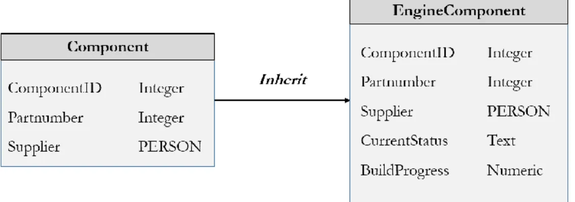
Inheritance
In object-oriented programming, inheritance enables new objects, called children, to inherit the certain properties of parent objects. A child inherits visible properties and methods from its parent with a capability of adding additional properties and methods to itself, as the figure 2.6:
Figure 2.6: Inheritance of an existing data object in object model.
20 Ct. [HOROWITZ 1991] pp. 1-38.
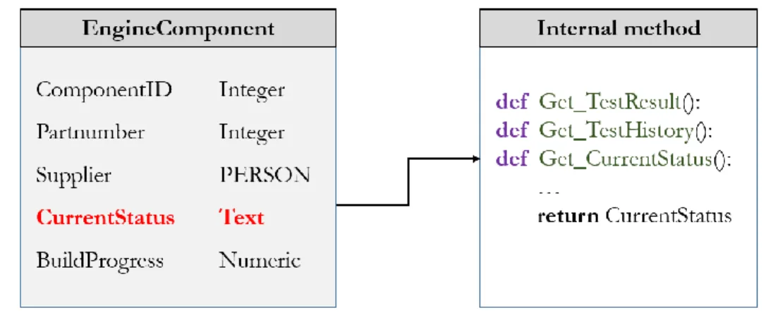
Encapsulation
A simplified and understandable way to use the created objects without being aware of their complexity inside. By hiding the internal details and properties of the objects, developers can only operate the objects by normally and easily accessing over the existing methods of the objects. For instance, to get the current status of an engine equipment, developers only query through an operator instead of executing several operations in the objects. When the operator is called, the internal methods will be executed and return value to the operator. Thus, developers can get the current status of the engine component without being aware of the internal hidden methods, illustrated as the figure below:
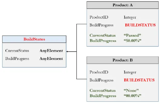
Figure 2.7: Encapsulation of a data object in object model. Polymorphism
In the object-oriented programming, polymorphism or pseudo-typing is used to make applications more modular and extensible by providing a powerful way to create interchangeable objects which can be manipulated as needs. For instance, an interchangeable operator is create without being specified its data type. This makes a number of connecting objects able to access the operator at the same time and manipulate data over it without being aware of the specified data type, the realization of polymorphism is demonstrated in the figure 2.8:
Figure 2.8: Realization of polymorphism in object model.
In the figure, a polymorphic type “BuildStatus” is created as an interchangeable operator and also simultaneously assigned completely different values by tables “Product: A” and “Product: B”. By taking the advantage of polymorphism, when developers perform querying to get the current status of all tables currently existing in the structure, the developers only execute a query command through the operator of the polymorphic type, then both different stored data assigned by the 2 tables will be automatically returned to the developers.
The techniques of object-oriented programming provided by the object database model greatly offer developers a huge advantages in application development as well as data management in developing database systems. These following characteristics of this model also serve the major benefits to developers as well as users in various point of views in software engineering:
Ease of maintenance
Most of the processes in the implemented system are fully encapsulated that can be reused and safely incorporated into new behaviors. It greatly reduces maintenance costs, in term of programming efforts and also complex problem solving. Furthermore, system resource consumption can also be minimized, on the other hands, as well as maximize the lifetime of the database system.
Reliable and flexible
New behaviors within an object-oriented system can be built by a reuse of existing created objects by dynamically called and accessed to create new objects anytime. The new created objects, called children, may inherit data attributes or even internal user-developed methods from existing one or many other objects, called the parent or parents, without effecting the existing systems functions. Furthermore, new user-developed methods can also be added to a single new created object without effecting others.
Reusability
A new created data object will automatically inherit everything from the parent class where is was spawned. The data attributes and object characteristics will be inherited to the new object. Meanwhile, the object will also automatically inherit the data and behaviors from its parent classes in which it participates to the entire data object layers underneath.
Real-world modeling
The object model tends to effectively reflect and response demands of businesses in order to develop database system using a model which supports a real world data structure of the organizations which are generally designed by using hierarchical structure. As following the object-oriented concept, the stored data are represented as objects and organized into several multi-level classes, and each object is associated with own behaviors21.
By using more logical mechanisms in data handling, several disadvantages of the object model also emerge that hugely effect several process in database organization. These below points of view present the main drawbacks caused when implementing the model in real applications:
Schema modification
Although the implementation of object model offers several advantages, but any modification of the database schema in an OODBMS typically involve recompiling the entire persistent schema. A modification of object or class instance, e.g. inserting, deleting, or re-designing, entirely effects other related objects in the same class that interact with the modified one.
Language dependence
Operating an OODBMS is dependently executed by a specific object-oriented programming language via a specific Application Programming Interface (API), also known as a wrapper, which programmatically connects both sides of interacting partners, i.e. the internal database system and external connecting applications. Also modifying the API may technically require a huge redesigning or recompiling of the entire developed programming components.
Broken encapsulation
Because of the encapsulation of the object model, any manipulation performed on objects in an OODBMS is definitely highly dependent on the design of the schema. The structure allows users to execute an operation only in the way the system is designed without breaking the relationships among the stored data objects.
In contrast, the relational nature of the data, in the relation model, allows users to query any data element in any component of the database depending on the user’s rights. Also joining tables or classes of the stored objects is not possible in the object model, whereas the operation can be simply performed in the relational model. Thus, developers must compromise both relational and object models carefully in several perspectives of application development.
2.3.3 Object-relational model
In previous sections, the relational and the object models were discussed. Several advantages offered by the relational model powerfully facilitate the implementation of database system by providing numbers of strong mechanisms in order to maintain several aspects of storing data in the database. Anyway, the major weaknesses of implementing the relational model in database for business applications are the effort and expertise of developers which require a high system designing skills to properly construct the system to support huge amount of incoming data with various different data types22.
Meanwhile, the systematic and concrete relationships of the stored data objects of the object model lead a high complexity in data handling. Any modification made to the stored may break the entire structure or at least the structure must be recompiled. Also, in favor of accessing data objects, the
well-structured database schema only allows users to accessing a data object by strictly following the encapsulated processes.
Throughout the evolution of database systems, a new hybrid data modeling approach, called the “object-relational model”, which is operated by an ORDBMS, was introduced to model a database system as a middleman between relational and object models to minimize the conceptual gap of the different data organizational approaches which is called the “object-relational impedance mismatch” by bridging the strengths of both models to enhance the performance of database system as well as facilitates a higher performance for the system. The major points of the object-relation impedance mismatch are presented as follows:
Data representation
The relational model represents data in tabular form which a table contains a number of records, and each of record contains a number of attributes, as the figure 2.9(a). In contrast, the object model represents data in the form of objects that each single object has its own properties, as the figure 2.9(b). The impedance mismatch is illustrated as follows:
(a)
(b)