Document No:
G1-PP-QRT-GDL-0001Revision:
6Revision Date:
15 April 2014Copy No:
IP Security:
PublicBarrow Island Quarantine:
Terrestrial and Marine Quarantine
Management System
Table of Contents
1.0 Introduction ... 9
1.1 Proponent ... 9
1.2 Project ... 9
1.3 Location ... 9
1.4 Terminology, Definitions, and Abbreviations ... 12
1.5 Environmental Approvals ... 12
1.6 Purpose of this Quarantine Management System ... 13
1.6.1 Legislative Requirements ... 13 1.6.2 Objectives ... 14 1.6.3 Requirements ... 14 1.6.4 Scope ... 14 1.6.5 Hierarchy of Documentation ... 14 1.7 Components of the QMS ... 19
1.7.1 Embedding the Quarantine Management System within OEMS ... 20
1.8 Stakeholder Consultation – Development of the QMS ... 21
1.8.1 Historical and Ongoing Consultation ... 21
1.8.2 Public Availability ... 24
1.9 DPaW Access to Sites where the QMS Applies ... 25
2.0 Relevant Facilities and Activities ... 26
2.1 Terrestrial Facilities ... 26
2.1.1 Overview ... 26
2.1.2 Gas Treatment Plant ... 26
2.1.3 Carbon Dioxide Injection System ... 27
2.1.4 Associated Terrestrial Infrastructure ... 27
2.1.5 Areas Impacted for Seismic Data Acquisition ... 28
2.1.6 Onshore Feed Gas Pipeline System and Terrestrial Component of the Shore Crossing (Gorgon and Jansz) ... 28
2.2 Marine Facilities ... 31
2.2.1 Overview ... 31
2.2.2 Materials Offloading Facility (MOF) ... 31
2.2.3 LNG Jetty ... 32
2.2.4 Dredge Spoil Disposal Ground ... 32
2.2.5 Offshore Feed Gas Pipeline System ... 34
2.2.6 Domestic Gas Pipeline ... 34
2.2.7 Marine Upgrade of the Existing WAPET Landing ... 34
4.0 Barrow Island Quarantine Policy ... 38
5.0 Quarantine Risk Management ... 39
5.1 Quarantine Risk Assessment ... 39
5.1.1 Quarantine Risk Assessment Methodology ... 39
5.1.2 Quarantine Barrier Selection ... 41
5.1.3 Quarantine Risk Register ... 41
5.2 HES Risk Management ... 42
5.2.1 Methodology ... 42
6.0 Management Measures Supporting Environmental Stewardship ... 44
6.1 Management Measures to Prevent Introductions of NIS and Marine Pests ... 44
6.1.1 Quarantine Guidelines ... 44
6.1.2 Quarantine Procedures ... 47
6.1.3 Quarantine Specifications ... 48
6.1.4 Quarantine Checklists ... 49
6.2 Measures to Detect NIS and Marine Pests Early Enough to Consider Eradication ... 51
6.2.1 Observation ... 51
6.2.2 Surveillance ... 52
6.2.3 Monitoring ... 53
6.3 Measures to Control and Eradicate NIS and Marine Pests ... 53
6.3.1 Quarantine Species Action Plan Framework ... 53
6.3.2 Quarantine Species Action Plans ... 54
6.3.3 Managing NIS and Marine Pests on Barrow Island and its Surrounding Waters .... 55
6.4 Quarantine Management Plans ... 56
6.4.1 Management Plans for EPCM and Contractors ... 56
6.4.2 Management Plans for Specialised Activities ... 57
6.4.3 Management Plans for Facilities ... 57
6.4.4 Management Plans for Marine Vessels ... 57
6.5 Zonation as a Management Measure ... 57
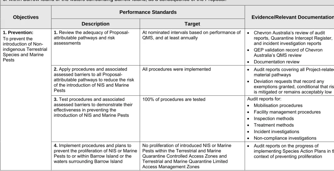
7.0 Objectives, Performance Standards, and Relevant Documentation ... 59
7.1 Overview ... 59
7.2 Objectives... 59
7.3 Performance Standards ... 59
7.4 Relevant Documentation ... 59
7.5 Process for Determining Performance Standards ... 59
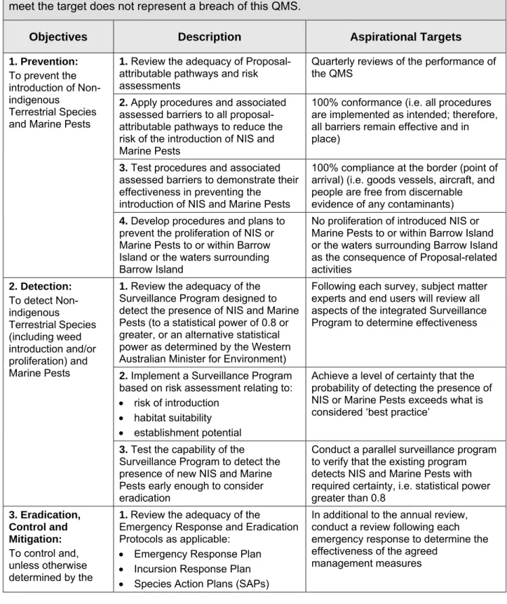
7.6 Aspirational Targets ... 60
8.0 Implementation ... 67
8.1 Environmental Management Documentation ... 67
8.1.2 Gorgon Gas Development and Jansz Feed Gas Pipeline Documentation ... 67
8.2 Safe Operations ... 68
8.2.1 Competency Development ... 68
8.2.2 Structure, Roles and Responsibility ... 70
8.2.3 Communication ... 71
8.2.4 Quarantine Information Management ... 72
8.2.5 Continuous Improvement ... 73
8.3 Facility Design and Construction ... 73
8.3.1 Buildings and Facilities ... 73
8.3.2 Infrastructure and Equipment Associated with Facilities ... 73
8.4 Third-party Contractors ... 74
8.4.1 Contractor and Subcontractor Documentation ... 74
8.4.2 Operation Control of Contractors and Subcontractors ... 74
8.5 Procedural Deviations and Quarantine Intercepts ... 75
8.5.1 Procedural Deviation Investigation and Corrective Action ... 75
8.5.2 Intercepts Investigation and Corrective Action ... 75
8.6 Incident Investigation ... 75
8.7 Emergency Management ... 76
8.7.1 Emergency Response Plan ... 76
8.7.2 Quarantine Incursion Response Plan ... 76
8.8 Management of Change ... 76
9.0 Auditing, Reporting and Review ... 78
9.1 Auditing ... 78
9.1.1 Internal Auditing ... 78
9.1.2 External Auditing ... 78
9.2 Reporting ... 78
9.2.1 Compliance Reporting ... 78
9.2.2 Environmental Performance Reporting ... 79
9.2.3 Quarantine Audit Reporting to DPaW and the Conservation Commission ... 79
9.2.4 Routine Internal Reporting ... 79
9.2.5 Incident Response and Reporting ... 79
9.3 Review of this QMS ... 80
9.3.1 Management Review ... 81
10.0 References ... 82
Appendix 1 Terminology, Definitions and Abbreviations ... 86
Appendix 2 Chevron Integrated Risk Prioritization Matrix ... 103
Appendix 5 Identification and Risk Assessment of Terrestrial Matters of National
Environmental Significance (NES) ...127
Appendix 6 Identification and Risk Assessment of Marine Matters of National Environmental Significance (NES) ...128
Appendix 7 Compliance Reporting Table ...129
List of Tables Table 1-1 OE Elements and their Goals ... 20
Table 7-1 Objectives, Performance Standards, and Relevant Documentation ... 61
Table 7-2 Aspirational Targets ... 65
Table 9-1 Incident and Observations Reporting Requirements ... 80
List of Figures Figure 1-1 Location of the Greater Gorgon Area ... 10
Figure 1-2 Location of the Gorgon Gas Development and Jansz Feed Gas Pipeline ... 11
Figure 1-3 Flow Diagram of the Quarantine Management System ... 15
Figure 1-4 Hierarchy of Gorgon Gas Development Environmental Documentation ... 17
Figure 1-5 Hierarchy of Jansz Feed Gas Pipeline Environmental Documentation ... 18
Figure 1-6 Deliverable Development, Review and Approval Flow Chart ... 24
Figure 2-1 Gorgon Gas Development and Jansz Feed Gas Pipeline Terrestrial Facilities on Barrow Island ... 30
Figure 2-2 Gorgon Gas Development Marine Facilities and Dredging and Spoil Disposal Zones of High Impact, Moderate Impact, and Zone of Influence ... 33
1.0 Introduction
1.1 Proponent
Chevron Australia Pty Ltd (Chevron Australia) is the proponent and the person taking the action for the Gorgon Gas Development on behalf of the following companies (collectively known as the Gorgon Joint Venturers):
Chevron Australia Pty Ltd
Chevron (TAPL) Pty Ltd
Shell Development (Australia) Pty Ltd
Mobil Australia Resources Company Pty Limited
Osaka Gas Gorgon Pty Ltd
Tokyo Gas Gorgon Pty Ltd
Chubu Electric Power Gorgon Pty Ltd
pursuant to Statement No. 800 and EPBC Reference: 2003/1294 and 2008/4178.
Chevron Australia is also the proponent and the person taking the action for the Jansz Feed Gas Pipeline on behalf of the Gorgon Joint Venturers, pursuant to Statement No. 769, and EPBC Reference: 2005/2184.
1.2 Project
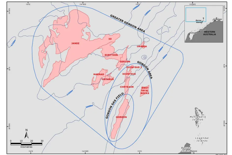
Chevron Australia proposes to develop the gas reserves of the Greater Gorgon Area (Figure 1-1).
Subsea gathering systems and subsea pipelines will be installed to deliver feed gas from the Gorgon and Jansz–Io gas fields to the west coast of Barrow Island. The feed gas pipeline system will be buried as it traverses from the west coast to the east coast of the Island where the system will tie in to the Gas Treatment Plant located at Town Point. The Gas Treatment Plant will comprise three Liquefied Natural Gas (LNG) trains capable of producing a nominal capacity of five Million Tonnes Per Annum (MTPA) per train. The Gas Treatment Plant will also produce condensate and domestic gas. Carbon dioxide (CO2), which occurs naturally in the
feed gas, will be separated during the production process. As part of the Gorgon Gas Development, Chevron Australia will inject the separated CO2 into deep formations below
Barrow Island. The LNG and condensate will be loaded from a dedicated jetty offshore from Town Point and then transported by dedicated carriers to international markets. Gas for domestic use will be exported by a pipeline from Town Point to the domestic gas collection and distribution network on the mainland.
1.3 Location
The Gorgon gas field is located approximately 130 km and the Jansz–Io field approximately 200 km off the north-west coast of Western Australia. Barrow Island is located off the Pilbara coast 85 km north-north-east of the town of Onslow and 140 km west of Karratha. The Island is approximately 25 km long and 10 km wide and covers 23 567 ha. It is the largest of a group of islands, including the Montebello and Lowendal Islands.
1.4 Terminology,
Definitions, and Abbreviations
Terms and definitions that apply to this Quarantine Management System (QMS) are listed in Appendix 1.
1.5 Environmental
Approvals
The initial Gorgon Gas Development was assessed through an Environmental Impact Statement/Environmental Review and Management Programme (EIS/ERMP) assessment process (Chevron Australia 2005, 2006).
The initial Gorgon Gas Development was approved by the Western Australian State Minister for the Environment on 6 September 2007 by way of Ministerial Implementation Statement No. 748 (Statement No. 748) and the Commonwealth Minister for the Environment and Water Resources on 3 October 2007 (EPBC Reference: 2003/1294).
In May 2008, under section 45C of the Western Australian Environmental Protection Act 1986 (EP Act), the Environmental Protection Authority (EPA) approved some minor changes to the Gorgon Gas Development that it considered ‘not to result in a significant, detrimental, environmental effect in addition to, or different from, the effect of the original proposal’ (EPA 2008). The approved changes are:
excavation of a berthing pocket at the Barge (WAPET) Landing facility
installation of additional communications facilities (microwave communications towers) relocation of the seawater intake
modification to the seismic monitoring program
In September 2008, Chevron Australia sought both State and Commonwealth approval through a Public Environment Review (PER) assessment process (Chevron Australia 2008) for the Revised and Expanded Gorgon Gas Development to make some changes to ‘Key Proposal Characteristics’ of the initial Gorgon Gas Development, as outlined below:
addition of a five MTPA LNG train, increasing the number of LNG trains from two to three
expansion of the CO2 Injection System, increasing the number of injection wells and surface drill locations
extension of the causeway and the Materials Offloading Facility (MOF) into deeper water The Revised and Expanded Gorgon Gas Development was approved by the Western Australian State Minister for the Environment on 10 August 2009 by way of Ministerial Implementation Statement No. 800 (Statement No. 800). Statement No. 800 also superseded Statement No. 748 as the approval for the initial Gorgon Gas Development. Statement No. 800 therefore provides approval for both the initial Gorgon Gas Development and the Revised and Expanded Gorgon Gas Development, which together are known as the Gorgon Gas Development. Amendments to Statement No. 800 Conditions 18, 20 and 21 under section 46 of the EP Act were approved by the Western Australian State Minister for the Environment on 7 June 2011 by way of Ministerial Implementation Statement No. 865 (Statement No. 865). Therefore, implementation of the Gorgon Gas Development will be in accordance with Statement No. 800 (as amended by Statement No. 865).
On 26 August 2009, the then Commonwealth Minister for the Environment, Heritage and the Arts issued approval for the Revised and Expanded Gorgon Gas Development (EPBC Reference: 2008/4178) and varied the conditions for the initial Gorgon Gas Development (EPBC Reference: 2003/1294).Since the Revised and Expanded Gorgon Gas Development was approved, further minor changes have also been made and/or approved to the Gorgon Gas
Development and are now also part of the Development. Further changes may also be made/approved in the future. This QMS relates to any such changes, and where necessary will be specifically revised to address the impacts of those changes.
Use of an additional 32 ha of uncleared land for the Gorgon Gas Development Additional Construction, Laydown, and Operations Support Area (Additional Support Area) was approved by the Western Australian State Minister for Environment on 2 April 2014 by way of Ministerial Implementation Statement No. 965 and by Variation issued by the Commonwealth Minister for the Environment. Statement No. 965 applies the conditions of Statement No.800 to the Additional Support Area and requires all implementation, management, monitoring, compliance assessment and reporting, environmental performance reporting, protocol setting and record keeping requirements applicable to the Additional Support Area under Statement No.800 to be carried out on a joint basis with the Gorgon Gas Development.
The Jansz Feed Gas Pipeline was assessed via Environmental Impact Statement/Assessment on Referral Information (ARI) and EPBC Referral assessment processes (Mobil Australia 2005, 2006).
The Jansz Feed Gas Pipeline was approved by the Western Australian State Minister for the Environment on 28 May 2008 by way of Ministerial Implementation Statement No. 769 (Statement No. 769) and the Commonwealth Minister for the Environment and Water Resources on 22 March 2006 (EPBC Reference: 2005/2184).
This QMS covers the Gorgon Gas Development as approved under Statement No. 800, and as approved by EPBC Reference: 2003/1294 and EPBC Reference: 2008/4178, and including the Additional Support Area as approved by Statement No. 965 and as varied by the Commonwealth Minister for the Environment. In addition, this QMS covers the Jansz Feed Gas Pipeline as approved by Ministerial Implementation Statement No. 769 and EPBC Reference: 2005/2184.
In respect of the Carbon Dioxide Seismic Baseline Survey Works Program, which comprises the only works approved under Statement No. 748 before it was superseded, and under EPBC Reference: 2003/1294 before the Minister approved a variation to it on 26 August 2009, note that under Condition 1A.1 of Statement No. 800 and Condition 1.4 of EPBC Reference: 2003/1294 and 2008/4178 this Program is authorised to continue for six months subject to the existing approved plans, reports, programs and systems for the Program, and the works under that Program are not the subject of this QMS.
1.6
Purpose of this Quarantine Management System
1.6.1 Legislative
Requirements
1.6.1.1 State Ministerial Conditions
This QMS is required under Condition 10.1 of Statement No. 800, which is quoted below:
“Prior to commencement of construction of any terrestrial facilities listed in Condition 6.3 and the marine facilities listed in Condition 14.3, the Proponent shall submit the Quarantine Management System (QMS) to the Minister, taking into account the advice of the Quarantine Expert Panel (QEP) that meets the aim and objectives set out in Condition 10.3 and the requirements of Condition 10.4, as determined by the Minister, unless otherwise allowed in Condition 10.2”
This QMS is also required under Condition 10.1 of Statement No. 769; i.e.
“Prior to commencement of construction of any terrestrial facilities listed in Condition 6.3 and the marine facilities listed in Condition 12.3, the Proponent shall submit the QMS to
1.6.1.2 Commonwealth Ministerial Conditions
This QMS satisfies Condition 8.1 of EPBC Reference: 2003/1294 and Condition 8.1 of EPBC Reference: 2008/4178, which is quoted below:
“Prior to commencement of construction of any terrestrial facilities listed in Condition 5.2 and the marine facilities listed in Condition 11.3, the person taking the action must submit the Quarantine Management System (QMS) to the Minister, for approval, taking into account the advice of the Quarantine Expert Panel (QEP) established under the Western Australian Minister’s approval for the action, unless otherwise allowed in Condition 8.2.”
1.6.2 Objectives
The objective of this QMS, as stated in Condition 10.3 of Statement No. 800, Condition 10.3 of Statement No. 769, and Condition 8.3 of EPBC Reference: 2003/1294 and 2008/4178, is that the Proponent shall not introduce or proliferate Non-indigenous Terrestrial Species and Marine Pests to or within Barrow Island or the waters surrounding Barrow Island, as a consequence of the Proposal.
The specific objectives of the QMS are to:
prevent the introduction of Non-indigenous Terrestrial Species and Marine Pests
detect Non-indigenous Terrestrial Species (including weed introduction and/or proliferation) and Marine Pests
control and, unless otherwise determined by the Minister, eradicate detected Non-indigenous Terrestrial Species (including weeds) and Marine Pests
mitigate adverse impacts of any control and eradication actions on indigenous species taken against detected Non-indigenous Terrestrial Species (including weeds) and Marine Pests.
1.6.3 Requirements
The requirements of this QMS, as stated in Condition 10 of Statement No. 800, Condition 10 of Statement No. 769, and Condition 8 of EPBC Reference: 2003/1294 and 2005/2184, are listed in Appendix 3.
1.6.4 Scope
The QMS governs all materials, personnel, vessels, and aircraft travelling to Barrow Island, the smaller surrounding islands, and surrounding waters. The QMS also ensures that quarantine is integrated into the initial planning of all projects on Barrow Island, the smaller surrounding islands, and surrounding waters.
Any matter specified in the QMS is relevant to the Gorgon Gas Development or Jansz Feed Gas Pipeline only if that matter relates to the specific activities or facilities associated with that particular development.
1.6.5 Hierarchy
of
Documentation
This QMS will be implemented for the Gorgon Gas Development and the Jansz Feed Gas Pipeline via the Chevron Australasia Business Unit (ABU) Operational Excellence Management System (OEMS). The OEMS is the standardised approach that applies across the ABU to continuously improve the management of safety, health, environment, reliability, and efficiency to achieve world-class performance.
Implementation of the OEMS enables the Chevron ABU to integrate its Operational Excellence (OE) objectives, processes, procedures, values, and behaviours into the daily operations of Chevron Australia personnel and contractors working under Chevron Australia’s supervision. The OEMS is designed to be consistent with and, in some respects, go beyond ISO 14001:2004
(Environmental Management Systems – Requirements with Guidance for Use) (Standards Australia/Standards New Zealand 2004).
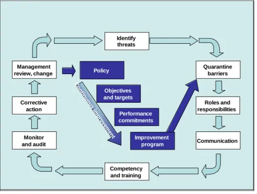
Roles and responsibilities Quarantine barriers Identify threats Communication Monitor and audit Corrective action Management review, change Competency and training Policy Objectives and targets Performance commitments C on tin uo u s im p ro vem ent Improvement program
Figure 1-3 Flow Diagram of the Quarantine Management System
The actions reflected in Figure 1-3 represent two distinct yet interrelated components, namely the core control components and the operational components.
The core control components are:
establish a policy for quarantine management, and set the direction for continuous improvement of the system. Implement the policy through improvement objectives, targets and action plans
set objectives, targets, and the associated performance commitments
undertake continuous improvement based on audits, lessons learnt, workplace assessments, and other industry benchmarks.
The second group of activities relate to typical operational responsibilities, namely:
define the management measures to be implemented to minimise quarantine risks develop quarantine barriers and incorporate these measures into designs, procedures,
and specifications detailed in quarantine procedures; identify roles and responsibilities for personnel implementing management measures and ensure that these responsibilities have been clearly and effectively communicated
ensure all personnel are trained and are competent to perform their tasks
conduct measurement and verification to ensure the system represents best practice and demonstrates leadership in quarantine management. Perform monitoring, inspections, and audits to verify that management measures are being properly implemented and that they are effective
correcting. The system should also identify what actions need to be taken to improve performance and reduce risk
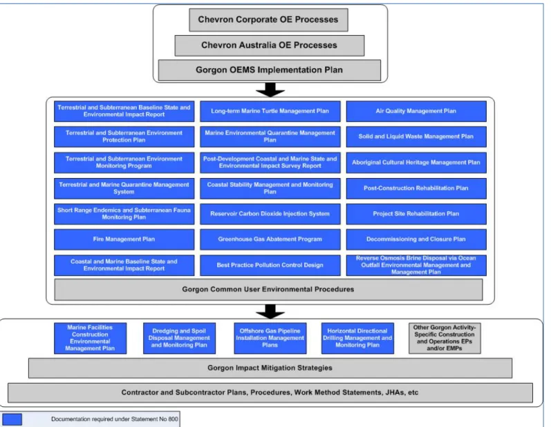
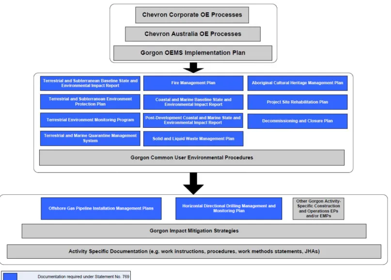
incorporate a management of change process for identifying changes to operational activities or processes that could have an impact on quarantine, and for defining and implementing measures to minimise the quarantine risks associated with these changes. Figure 1-4 and Figure 1-5 provide an overview of the overall hierarchy of environmental management documentation within which this QMS exists. Further details on environmental management documentation for the Gorgon Gas Development and Jansz Feed Gas Pipeline are provided in Section 8.0 of this QMS.
Figure 1-5 Hierarchy of Jansz Feed Gas Pipeline Environmental Documentation
1.7
Components of the QMS
As part of the Chevron ABU, the Gorgon Gas Development and Jansz Feed Gas Pipeline is governed by the requirements of the ABU OEMS, within which a number of OE Processes exist. The Gorgon Gas Development and Jansz Feed Gas Pipeline will implement internally those OE Processes (and supporting OE Procedures) that apply to the Gorgon Gas Development and Jansz Feed Gas Pipeline’s activities, where it is appropriate and reasonably practicable to do so.
The key OE Processes taken into account during the development and subsequent revisions of this QMS, with a description of the intent of each Process, are:
HES Risk Management Process Upstream and Gas (OE-03.01.01; Chevron Australia 2012): The purpose of this process is to identify and address health, environment, and safety (HES) risks of facilities and activities related to the Gorgon Gas Development and Jansz Feed Gas Pipeline.
Environmental Stewardship Process (OE-07.01.02; Chevron Australia 2012a): This process applies during the operations phase of the Gorgon Gas Development and Jansz Feed Gas Pipeline. This process is designed to identify, assess, and manage potentially significant environmental impacts in a consistent manner and to continually improve environmental performance. A key business value objective is alignment with ISO 14001 (Standards Australia/Standards New Zealand 2004).
Hazardous Communication Process (OE-03.16.01; Chevron Australia 2012b): The purpose of this process is to establish the requirements for the communication of hazards associated with hazardous materials, and to eliminate or minimise the HES hazards associated with hazardous materials on ABU sites.
Management of Change Process (OE-04.01.01; Chevron Australia 2012c): This process focuses on ensuring an efficient and reliable process for implementing changes to organisational design, which includes the identification, control, and mitigation of OE-related incidents.
Contractor Health, Environment, and Safety Management Process (CHESM) (OE-06.00.01; Chevron Australia 2012d): The purpose of this process is to establish clear accountabilities, ensure active engagement of contractors, and provide a consistent CHESM program to eliminate HES incidents and injuries among contractors involved with the Gorgon Gas Development and Jansz Feed Gas Pipeline.
Competency Development and Assurance Process (OE-03.13.01; Chevron Australia 2012e): The purpose of this process is to provide a consistent and structured approach to building individual competency and overall organisational capability that will enable the ABU to achieve its business objectives.
Incident Investigation and Reporting Process (OE-09.00.01; Chevron Australia 2012f): The purpose of this process is to report and investigate incidents, including injury, operational, near miss, occupational illness, environmental (including quarantine), reliability, business disruption, and community concern. The lessons learnt can then be used to prevent future incidents.
Emergency Management Process (OE-11.01.01; Chevron Australia 2012g): This process provides the organisational structures, management processes, and tools necessary to respond to emergencies and to prevent or mitigate emergency and/or crisis situations.
Compliance Assurance Process (OE-12.01.01; Chevron Australia 2012h): This process addresses compliance with legal, internal and external safety, health, environment,
1.7.1
Embedding the Quarantine Management System within OEMS
Quarantine management is primarily a biodiversity strategy aimed at protecting the conservation values of Barrow Island and its surrounding waters. This is done by aligning all quarantine management measures with the applicable OE Processes and associated OE Expectations, which are arranged into OE Elements. OEMS has 47 OE Expectations organised within 13 OE Elements. OE Elements spell out specific requirements for the management of safety, health, environment, reliability, and efficiency. The expectations are met through processes and programs put in place by local business unit management (e.g. the Australasia Business Unit [ABU]).
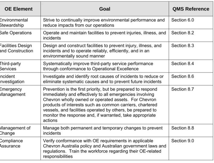
Of the 13 OE Elements, eight relate to and constitute the core of the Gorgon Gas Development QMS. These Elements, their respective QMS reference, and their goals are listed in Table 1-1.
Table 1-1 OE Elements and their Goals
OE Element Goal QMS Reference
Environmental
Stewardship Strive to continually improve environmental performance and reduce impacts from our operations
Section 6.0
Safe Operations Operate and maintain facilities to prevent injuries, illness, and
incidents Section 8.2
Facilities Design and Construction
Design and construct facilities to prevent injury, illness, and incidents and to operate reliably, efficiently, and in an environmentally sound manner
Section 8.3
Third-party
Services Systematically improve third-party service performance through conformance to Operational Excellence Section 8.4 Incident
Investigation Investigate and identify root causes of incidents to reduce or eliminate systematic causes and to prevent future incidents
Section 8.6
Emergency
Management Prevention is the first priority, but be prepared to respond immediately and effectively to all emergencies involving Chevron wholly owned or operated assets. For Chevron products of interests such as common carriers, chartered vessels, and facilities operated by others, be prepared to monitor the response and, if warranted, take appropriate actions
Section 8.7
Management of
Change Manage both permanent and temporary changes to prevent incidents Section 8.8 Compliance
Assurance Verify conformance with OE requirements in applicable Chevron Australia policy and Australian government laws and regulations. Train the workforce regarding their OE-related responsibilities
Section 9.0
The OE Elements and OE Processes relevant to quarantine management ensure that quarantine measures developed specifically for the Gorgon Gas Development and Jansz Feed Gas Pipeline remain aligned with the OE Vision, which is:
To be recognised and admired by industry and the communities in which we operate as world-class in safety, health, environment, reliability and efficiency.
1.8
Stakeholder Consultation – Development of the QMS
Regular consultation with stakeholders was undertaken by Chevron Australia throughout the initial development of the environmental impact assessment management documentation for the Gorgon Gas Development and Jansz Feed Gas Pipeline. This stakeholder consultation included engagement with the community, government departments, industry operators, and contractors to Chevron Australia via planning workshops, risk assessments, meetings, teleconferences, and the PER, EIS/ERMP and Environmental Review (Chevron Australia 2013) formal approval processes.
This document has been prepared with input from:
The Quarantine Expert Panel (QEP): Members of the QEP reviewed this document and their comments have been incorporated or otherwise resolved. The QEP is required to provide advice on quarantine matters including the development and implementation of the QMS. The QEP has endorsed this QMS and its advice was provided in the document : Report provided to the Minister for Environment and Chevron Australia Pty Ltd on the Adequacy of the Development of the Gorgon Quarantine Management System (Quarantine Expert Panel 2009).
The QEP contains subject matter experts from Western Australian Department of Parks and Wildlife (DPaW), Western Australian Department of Agriculture and Food (DAFWA), Western Australian Department of Fisheries (DoF), independent experts, and representatives of Chevron Australia.
The Western Australian Department of Environment and Conservation (DEC) (now Department of Parks and Wildlife [DPaW]): Workshops and meetings were held involving the DEC and Chevron Australia personnel to discuss the scope and content of this QMS during its development. The DEC reviewed a draft revision of this QMS along with the feedback of the QEP. The DEC’s comments have been incorporated or otherwise resolved.
The Commonwealth Department of Environment, Water, Heritage and the Arts (DEWHA) (now Department of the Environment [DotE]): DEWHA reviewed and commented on a draft revision of this QMS along with the feedback of the QEP. DEWHA’s comments have been incorporated or otherwise resolved.
1.8.1 Historical
and
Ongoing Consultation
1.8.1.1 Overview of Historical Consultation
Since 2003, substantial and continuous consultation has occurred throughout the process of developing the quarantine management measures for the Gorgon Gas Development and Jansz Feed Gas Pipeline. In EPA Bulletin 1221 (EPA 2006), the EPA recognised this:
‘...the EPA is satisfied as to the expertise of the people involved in both making the risk estimates in workshops and providing guidance via an expert advisory panel convened by the proponent.’
The Bulletin went on to record:
‘...this activity has involved a large amount of work by the proponent, its consultants and officers of a number of government agencies participating in public meetings, workshops and expert panel briefings.’
It was also recorded that during the initial development phase of the QMS, and consistent with the EPA’s recommendation in Bulletin 1101 (EPA 2003):
‘... the proponent organised a number of community and expert meetings and supporting processes to develop standards acceptable to the community and expert
rigorous involving experts and community members to define acceptable levels of risk for the establishment of Non-indigenous Species on Barrow Island’.
This was reflected in the public submissions where one responder congratulated Chevron Australia on this process. The EPA believes that the process was credible and helpful in establishing a public view on acceptable risk.
1.8.1.2 Public Consultation – Historical
Chevron Australia convened five comprehensive community consultation meetings during 2004 and 2005. These meetings were widely advertised and well attended, independently chaired, and provided clear evidence of community input into the development of standards for acceptable risk, the process for developing quarantine barriers to meet acceptable risk standards, the approach for the development of the QMS, and reports of studies and surveys of interest to stakeholders.
Interested stakeholders, each of which reported back to the wider community consultation meetings, also convened four special community workshops. These lengthy workshops enabled stakeholders to provide direct assistance in the development of standards for acceptable risk, and provided input on the content and structure of the QMS.
Chevron Australia regularly responded to the requests of community groups and non-government organisations to discuss the status and progress of activities during development of the QMS. Records of QEP and Quarantine Advisory Committee (QAC) meetings, workshop reports, community consultation reports, and community workshop reports were all published on a publicly accessible website that was accessed thousands of times during the development of the QMS.
1.8.1.3 Subject Matter Expert Consultation – Historical and Ongoing
Since 2003, Chevron Australia has consulted with a large community of independent technical experts from government, scientific organisations, and independent specialists.
The QEP was convened nine times between 2003 and 2005, and involved representatives of State and Commonwealth government departments, independent risk assessment specialists, and independent conservation and biosecurity specialists. Following submission of the Draft EIS/ERMP (Chevron Australia 2005), the QAC was convened six times between 2006 and 2008 to continue consultation with experts on the development of the QMS. The involvement of independent experts included activities such as the preparation of desktop and field surveys to address information gaps identified by the QEP and QAC. A new QEP was convened in 2008 under Chevron Australia’s commitment for continuing expert consultation, as directed by Statement No. 800. This panel meets quarterly.
From 2004 to 2006, 30 independent experts were involved in 33 risk assessment workshops for identifying quarantine threats and developing barriers that were judged to reduce the risk of introduction of a Non-indigenous terrestrial Species (NIS) or Marine Pest to acceptable levels. These experts contributed 133 days of independent advice and analysis (not including their preparation and follow-up efforts, which were often substantial). Further consultations with experts continue to improve the effectiveness of selected barriers and contribute to the review of the QMS, consistent with Chevron Australia’s commitment to do so.
Since 2009, ongoing consultation with independent experts concerning the detection program continues to validate and improve Chevron Australia’s capability for detection early enough to enable eradication without substantial consequences to native flora and fauna.
Chevron Australia has also attended a number of scientific workshops and symposia to present their methodologies and gain helpful advice. The Cooperative Research Centre convened these events for National Plant Biosecurity, the Commonwealth Scientific and Industrial Research Organisation (CSIRO), the Australian Centre for Excellence in Risk Analysis, and DAFWA. Scientists from all over the world attended these events and the development of the QMS benefitted from their consultation.
In addition, several studies relating to the QMS have been peer-reviewed and published in scientific journals. The methodology for risk assessments have been widely presented at national and international conferences. This exposure to the wider scientific community has resulted in the methods developed for the Gorgon Gas Development and Jansz Feed Gas Pipeline being adopted as a new benchmark for biosecurity efforts elsewhere.
1.8.1.4 DPaW, DAFWA, and DoF Consultation – Historical and Ongoing
DEC (now DPaW) and DAFWA representatives were present at all community meetings and workshops, and DoF representatives were invited to and attended many of these events. In addition, the DEC was an observer at all Quarantine Hazard Analysis (QHAZ) workshops, which also involved DAFWA and DoF technical experts. DEC and DAFWA participated as observers in the QEP and QAC meetings.
Chevron Australia frequently consulted with DEC, DAFWA, and DoF technical specialists during the development of the QMS, particularly with regard to the technical feasibility of quarantine barriers, surveys, and desktop studies to address information gaps, and the design and operation of government surveillance programs.
Two consultative meetings were held with DEC; the first held on 18 December 2007, on the progress of the Gorgon Gas Development QMS, and the second in February 2009 on the progress of the CO2 Baseline Survey QMS. The latter can be considered as a trial for the Gorgon Gas Development QMS.
Since 10 December 2008, members of the QEP were offered the opportunity to review or comment on any aspect of the proposed QMS. DPaW (formerly DEC), DAFWA, and DoF have representatives on this panel. This offer resulted in numerous QMS documents being requested and reviewed for the purpose of providing advice to the Western Australian Minister for Environment on the adequacy of the QMS.
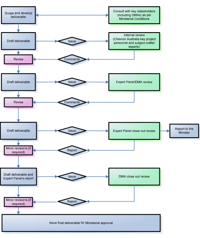
This consultation is continuous, via the QEP, and when the need arises these departments participate in discussions, with Chevron Australia, pertaining to the performance of the QMS. The process for development, review, and approval of this QMS is shown in Figure 1-6
1.8.1.5 Commonwealth Consultation – Historical and Ongoing
The Commonwealth government nominated a representative to the QEP from 2003 to 2005 and provided helpful input and advice as an observer. The Commonwealth government declined to nominate a representative to the subsequent QAC that met from 2006 to 2008.
Chevron Australia has consulted with the Commonwealth government continuously since 2003 outside the QEP and QAC meetings, and has published all its QMS development activities on a publicly available website to enable review of progress by the Commonwealth government and other interested stakeholders.
This consultation continues annually and when the need arises the Commonwealth government participates in discussions, with Chevron Australia, pertaining to the performance of the QMS. The process for development, review, and approval of this QMS is shown in Figure 1-6.
Figure 1-6 Deliverable Development, Review and Approval Flow Chart
1.8.2 Public
Availability
This QMS will be made public as and when determined by the Minister, under Condition 35 of Statement No. 800, Condition 20 of Statement No. 769, and Condition 22 of EPBC Reference: 2003/1294 and 2008/4178.
1.9
DPaW Access to Sites where the QMS Applies
On-Island DPaW Staff – DPaW may request access to any site where the QMS applies by applying to the Chevron Australia on-site Environmental/Quarantine Manager.
Off-Island DPaW Staff – DPaW may request access to any site where the QMS applies by applying to the Chevron Australia off-site Quarantine Manager.
Where access relates to specific health, environment, and safety requirements, the DPaW must ensure that all its personnel comply with relevant Chevron Australia requirements.
Note: Normal Barrow Island access arrangements apply and other statutory requirements may apply (see Memorandum of Understanding [MOU] and supporting documentation between DPaW and Chevron Australia: G1-CO-LTR-CVXPH-DECWH-0000228, G1-NT-REPX0002361, and G1-CO-EML-CVXPH-DECWH-0000053).
2.0
Relevant Facilities and Activities
2.1 Terrestrial
Facilities
2.1.1 Overview
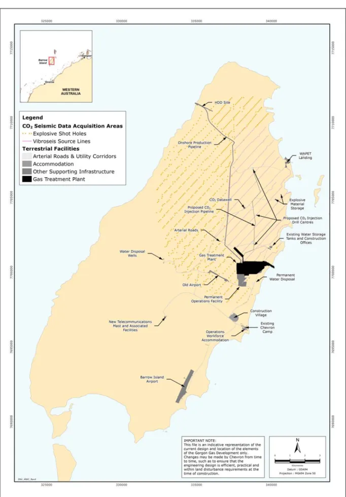
This QMS addresses issues associated with the Terrestrial Facilities of the Gorgon Gas Development and the Terrestrial Facilities of the Jansz Feed Gas Pipeline, which are shown in Figure 1-2 and Figure 2-1 of this QMS. The Gorgon Gas Development Terrestrial Facilities are defined in Condition 6.3 of Statement No. 800 and Condition 5.2 of EPBC Reference: 2003/1294 and 2008/4178, as the:
Gas Treatment Plant
Carbon Dioxide Injection System
Associated Terrestrial Infrastructure forming part of the Proposal Areas impacted for seismic data acquisition
the Onshore Feed Gas Pipeline System and terrestrial component.
Terrestrial Facilities also include those defined in Condition 6.3 of Statement No. 769 (the Onshore Feed Gas pipeline system and the terrestrial component of the Shore Crossing) and Schedule 1 of Statement No. 965 (the Additional Support Area).
Additional details on the Terrestrial Facilities can be found in the Draft EIS/ERMP (Chevron Australia 2005), the section 45C approval (EPA 2008), the PER (Chevron Australia 2008), and the Environmental Review (Chevron Australia 2013).
Activities associated with the CO2 Survey Program are briefly summarised in Section 2.1.3; however, more detailed information is provided in the ‘Proposed Activity’ section of the CO2 Seismic Baseline Survey Environmental Management Plan (G1-NT-REPX0001928).
Please note that the description of the Terrestrial Facilities provided in subsequent sections is as currently proposed. More specific details are contained in various Gorgon Gas Development approval and assessment documents, which are issued from time to time.
2.1.2
Gas Treatment Plant
The Gas Treatment Plant will be located near Town Point (Figure 2-1), on the east coast of Barrow Island. The Gas Treatment Plant includes:
LNG trains: 3 × 5 MTPA (nominal)
Gas Processing Drivers: 6 × 80 MW (nominal) gas turbines fitted with Dry Low NOx (DLN) burners
Power Generation: 5 × 116 MW (nominal) conventional gas turbines with DLN burners Flare design: Ground flare for the main plant flare; boil-off gas elevated flare in storage
and loading area
LNG Tanks: 2 × 180 000 m3 (nominal)
Condensate Tanks: 4 × 35 000 m3 (nominal).
The Gas Treatment Plant will produce three main products for export from Barrow Island: LNG for international export
domestic gas for use on the Australian mainland hydrocarbon condensate (light oil).
Typical Gas Treatment Plant processes are described in Chapter 6 of the Draft EIS/ERMP (Chevron Australia 2005).
2.1.3
Carbon Dioxide Injection System
Reservoir carbon dioxide (CO2) will be disposed of by injection into the Dupuy Formation more than 2000 m below Barrow Island to limit the greenhouse gas emissions and atmospheric pollutants associated with the Gorgon Gas Development and Jansz Feed Gas Pipeline’s production of LNG. The CO2 injection process is described in the Draft EIS/ERMP (Chevron Australia 2005).
The CO2 Injection System will consist of the mechanical components required to enable the injection of reservoir CO2 and manage the performance integrity of the injection facilities and the Dupuy Formation. These include:
CO2 compression facilities located within the Gas Treatment Plant boundary
an aboveground CO2 pipeline (approximately 10 km long in an 8 ha easement) between the Gas Treatment Plant and the three CO2 injection drill centres to the north
nine CO2 injection wells directionally drilled from the three CO2 injection drill centres north of the Gas Treatment Plant site (Figure 1-2)
observation wells for monitoring the subsurface spread of the CO2 plume
four pressure management water wells for managing pressure in the Dupuy Formation two pressure management water injection wells for the reinjection of water produced
from the lower Dupuy formation by pressure management wells. The water will be reinjected into the Barrow Group from a vertical depth of 1200 to 1600 m
shallow anode ground beds for the cathodic protection of all well types associated with the CO2 Injection Project. Additional anode wells will be drilled for cathodic protection purposes for the pressure management wells and the pressure management water injection wells (one anode well pair for each water producer/injector pair). An anode well will also be required for each stand-alone observation well.
Monitoring activities, including the acquisition of seismic data, will be undertaken as part of ongoing reservoir performance management. The total area occupied by the CO2 Injection System outside the Gas Treatment Plant site will be approximately 12.5 ha.
2.1.4
Associated Terrestrial Infrastructure
Terrestrial infrastructure associated with the Gorgon Gas Development consists of: the terrestrial component of the Barge (WAPET) Landing
the Construction Village
the Administration and Operations Complex
the permanent Utilities Area located within the Gas Treatment Plant
the Utilities Corridors between the Utilities Area and users within the Gas Treatment Plant and between the Utilities Area and the Construction Village, also servicing the Administration and Operations Complex
road upgrades, including the road between WAPET Landing and Town Point, and from Town Point to the Airport (via the Construction Village), and road along the feed gas pipeline system route
communications, consisting of a microwave communications tower and associated communications infrastructure to be installed on Barrow Island
onshore water supply infrastructure, consisting of a seawater demineralisation (reverse osmosis) plant, associated treated water and brine storage tanks, and treated water pumps and delivery piping to end users within the Gas Treatment Plant and utility corridors, reverse osmosis brine disposal pumps and the terrestrial component of the reverse osmosis brine pipeline
Associated terrestrial infrastructure will be primarily located in the vicinity of, and south of, the Gas Treatment Plant site on the east coast of Barrow Island (Figure 2-1).
2.1.5
Areas Impacted for Seismic Data Acquisition
The expansion of the CO2 plume injected into the Dupuy Formation below Barrow Island will be measured by comparing the reflection of vibrations through the subsurface. The terrestrial components of baseline seismic monitoring will use two vibration sources: subsurface explosives and vibroseis (Figure 2-1).
Approximately 1300 shot holes will be drilled for the placement of subsurface explosives. These will be drilled at 100 m intervals along lines spaced 500 m apart. The placement of explosives below the surface karst limestone layer will be done by drilling the holes to a depth of approximately 15 m below sea level. Purpose-built drill rigs that combine both sonic and air percussion drilling technology will be used, reducing the need to use drilling fluids. The charges will be 4 kg each and double detonators will be used.
Vibroseis consists of propagating energy signals into the earth from the surface via vibrator pads fitted to a truck. Vibroseis will be undertaken in the lower-lying, flatter terrain areas where good ground coupling is attainable and the effect on karst limestone is minimal. The vibroseis source lines will be spaced approximately 500 m apart, and the vibrator points will be every 12.5 m along these lines.
Seismic data acquisition is expected to be repeated a number of times throughout the life of the Gorgon Gas Development, in order to map the extent of the CO2 plume as it migrates. Differences between the data obtained during the baseline seismic monitoring and repeat seismic monitoring will be used to map the extent of the CO2 plume over time.
2.1.6
Onshore Feed Gas Pipeline System and Terrestrial Component of the
Shore Crossing (Gorgon and Jansz)
The Onshore Feed Gas Pipeline System will traverse Barrow Island from the west coast at North Whites Beach to the Gas Treatment Plant site near Town Point on the east coast (Figure 2-1). The pipeline system will be approximately 14 km long and located within a right-of-way between 30 and 45 m wide. The pipelines will be buried with excavated material backfilled into the trench.
The installation of the Onshore Feed Gas Pipeline System (including trenching, welding and pipe lowering) is expected to be completed at a rate of approximately 300 m to 350 m per day. The trench will be limited to approximately 2 km of open trench at any one time; however, the trench required for the pipeline systems (cables and tubes) will require the entire trench to be open for a relatively short period.
The terrestrial component of the Shore Crossing will consist of infrastructure for drilling eight horizontally directionally drilled (HDD) holes from the shore to an exit point approximately 500 m offshore, and insertion of pipe strings into these holes. A ninth hole will be drilled for a seawater intake system, which will provide water required for the activities associated with drilling and pre-commissioning.
The facilities required for construction of the Shore Crossing will include breakover supports and pipeline rollers for insertion of the pipelines. The HDD site will be approximately 80 m by 110 m.
The pipe stringing yard is located inland of the HDD site and includes a laydown area for the breakover supports and pipeline rollers. The portion of the stringing yard closest to the HDD site will be approximately 60 m wide and approximately 325 m long. The laydown area will extend an additional distance inland (up to 1010 m) at a narrower width (approximately 35 m).
Figure 2-1 Gorgon Gas Development and Jansz Feed Gas Pipeline Terrestrial Facilities on Barrow Island
2.2 Marine
Facilities
2.2.1 Overview
This QMS addresses issues associated with the Marine Facilities of the Gorgon Gas Development, which are shown in Figure 1-2 and Figure 2-2. The Gorgon Gas Development Marine Facilities are defined in Condition 14.3 of Statement No. 800 and Condition 11.3 of EPBC Reference: 2003/1294 and 2008/4178 as the:
Materials Offloading Facility (MOF) LNG Jetty
Dredge Spoil Disposal Ground
Offshore Feed Gas Pipeline System and marine component of the shore crossing Domestic Gas Pipeline.
For the purposes of Statement No. 800, Marine Facilities also include: marine upgrade of the existing WAPET Landing.
In relation to Statement No. 769, Marine Facilities are the Offshore Feed Gas Pipeline System and marine component of the shore crossing.
Additional details on the Marine Facilities can be found in the Draft EIS/ERMP (Chevron Australia 2005), the section 45C approval (EPA 2008), and the PER (Chevron Australia 2008). Please note that the description of the Marine Facilities provided in subsequent sections is as currently proposed. More specific details are contained in various Gorgon Gas Development approval and assessment documents, which are issued from time to time.
2.2.2
Materials Offloading Facility (MOF)
2.2.2.1 Pioneer MOF
A Pioneer MOF will initially be required to allow offloading of equipment and materials for construction of the onshore LNG plant and associated facilities on Barrow Island, via large barges and Roll-on/Roll-off (RORO) vessels. Construction activities will include:
construction of a Pioneer MOF perimeter berm, using a combination of suitably sized dredged material and rock transported from the mainland
placement of dredged material (approximately 200 000 m3) within the perimeter berm to form the Pioneer MOF Platform. Primary and secondary armour rock sourced from the mainland will be installed on the external face of the Pioneer MOF platform.
The berm construction will include dredged rock material and will be pervious in parts. A geotextile filter cloth will line the bunds prior to the infill operation. The geotextile liner will be protected by a screening layer and will be maintained until buried by the reclamation.
The fill material will be hydraulically placed by pumping via pipeline from the Trailer Suction Hopper Dredge positioned in the MOF turning basin. The placement of the fill will be primarily at or near high tides, limiting the hydraulic gradient between the inside and outside of the bund. This will limit the speed of the infill operation, thus allowing sufficient time for the fines within the MOF area to settle before subsequent loads.
Given the characteristics of the materials present within the dredging areas and their subsequent behaviour after having passed through a dredge pump, priority will be given to placing the coarser sand fraction onshore. This will result in lower turbidity levels from tail water discharge, more usable engineering fill grade material, and generally a reclamation area that is
The berm wall will include a steel weir box placed on the temporary face adjacent to the dredge area. The steel box will provide an adjustable weir on the upstream side and pipe outflow on the downstream side to discharge at or near the seabed.
2.2.2.2 Full MOF
Once the Pioneer MOF has been constructed, work will commence immediately on extending the MOF platform seaward and raising part of the existing MOF causeway, including:
extending the MOF platform seaward, forming a breakwater that will protect tug pen moorings, the heavy lift facility, and other berths. This work will be completed using material excavated from Barrow Island. Suitable dredge material may be used in place of core fill material from Barrow Island, depending on the quality and quantity of material won from Barrow Island. Up to 500 000 m3 of dredged material may be required for this purpose
constructing a heavy lift facility and tug pens
raising the existing MOF causeway by adding an upper causeway section (upper causeway height varies between +12 m to +16.5 m CD) to accommodate an all-weather access road to the LNG Jetty, a pipe rack containing LNG, condensate and other pipelines for export, and the operations of the jetty offloading facilities. This work will be completed using material excavated from Barrow Island
installing armour comprising precast concrete units.
2.2.3 LNG
Jetty
The design of the LNG Jetty is based on caissons connected by prefabricated pipeline and road trusses (≈70 m) (Kellogg Joint Venture 2009).
Jetty construction will include these activities:
prefabrication of caissons and pipe racks / road trusses transport to Barrow Island
placement of caissons on the seabed
installation and hook up of pipe racks and road trusses
placement of loading platform modules and some other prefabricated structures commissioning.
2.2.4
Dredge Spoil Disposal Ground
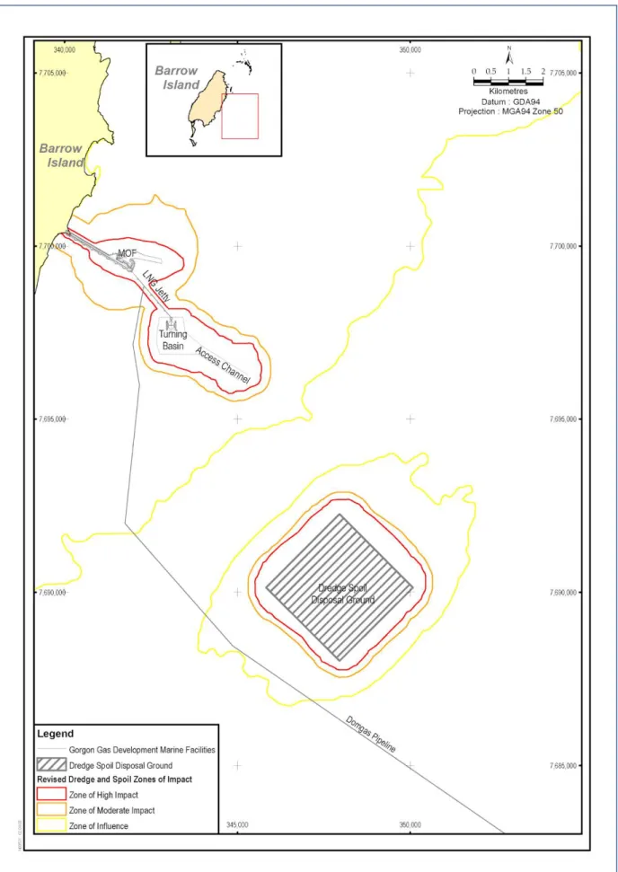
The Sea Dumping Permit (No. SD2004/0030) provides approval to dispose up to 8.5 million m3 of dredged material. The location of the approved spoil ground is defined by the following GDA94 MGA Zone 50 Coordinates:
347900 E 7692300 N 350050 E 7690050 N 347900 E 7688000 N 345750 E 7690050 N.
To control the disposal of dredged materials, the Spoil Disposal Ground will be divided into cells, each with an individual grid reference. A log will be maintained on board each vessel that records the number of loads disposed into each cell. Regular hydrographic surveys of the dredged material relocation site will be undertaken to confirm the developing bathymetry and the location of the disposal material.
Figure 2-2 Gorgon Gas Development Marine Facilities and Dredging and Spoil Disposal Zones of High Impact, Moderate Impact, and Zone of Influence
2.2.5
Offshore Feed Gas Pipeline System
The main offshore infrastructures (from the subsea manifold at the gas fields to the tail end of the HDD breakout point at North Whites Beach, Barrow Island) are:
Gorgon feed gas pipeline nominal 34” diameter (800 mm internal diameter, wall thickness 42.5 mm)
Gorgon monoethylene glycol (MEG) pipeline nominal 8” diameter (219 mm outer diameter, wall thickness 34.5 mm)
Gorgon utility pipeline nominal 6” diameter (219 mm outer diameter, wall thickness 35 mm)
Gorgon umbilicals nominal 5” diameter
Jansz feed gas pipeline from 24” to 30” diameter from subsea facilities to the continental shelf then 34” diameter pipeline to the shore crossing (550 mm to 800 mm internal diameter, wall thickness 42.5 mm)
Jansz MEG pipeline nominal 8” diameter (273 mm outer diameter, wall thickness 34.5 mm)
Jansz utility pipeline nominal 6” diameter (219 outer diameter, wall thickness 35 mm) Jansz umbilicals nominal 5” diameter.
The Offshore Feed Gas Pipeline systems will be installed on the seabed, via a pipelay vessel, from the subsea facilities at the Jansz gas field (approximately 1300 m water depth) and the Gorgon gas field (approximately 200 m water depth) to the shore crossing at North Whites Beach, on the west coast of Barrow Island. The pipelines will cross from Commonwealth waters to State waters in approximately 12.5 m water depth, at a distance of 3 nm from Barrow Island.
2.2.6
Domestic Gas Pipeline
Domestic gas will be exported via a domestic gas pipeline from Barrow Island to tie into the Dampier to Bunbury Natural Gas Pipeline on the mainland. The pipeline construction method will be as described in the Draft EIS/ERMP (Chevron Australia 2005). The route for this pipeline has been designed to avoid sensitive benthic habitat, where reasonably practicable.
2.2.7
Marine Upgrade of the Existing WAPET Landing
Prior to the completion of an operational Materials Offloading Facility (MOF), all vessel and freight movement (approximately 355 000 freight tonnes) for import and export from Barrow Island will use WAPET Landing, which is the only available landing point. Following construction of the MOF, WAPET Landing will continue to be used as an alternative materials offloading facility for Gorgon during peak periods.
The existing materials offloading facilities at WAPET Landing will be upgraded as described below.
2.2.7.1 Landing Craft Tank (LCT) Landing and Barge Berth
Increase landing craft capacity by installing additional ramps on either side of the existing concrete ramp. The new ramps will be formed by placing Flexmats (flexible concrete mattress) on prepared subgrade (approximately 1000 m3 of <75 mm) so as to achieve required ramp levels and grade.
A transition ramp (sunken barge) will be installed to act as a bridging structure to provide access and berthing of a barge. Approximately 45 m of seabed measured from the toe line of the existing LCT ramp will be disturbed to allow for placement of the transition ramp. The ramp will be floated into position, ballasted, and stabilised. Prior to the positioning of the transition ramp, compacted subgrade (hard, durable, angular rock
fragments, free from deleterious matter such as clay lump) will be placed on the seabed by a dump truck to achieve required levels and grade. The transition ramp will then be placed on the top of the compacted subgrade. In addition to ballast, piles will most likely be required to stabilise the sunken barge.
A steel ramp will be placed on the shore side of the barge to act as an approach ramp. A minimum of three breasting dolphins with fenders will be installed to assist berthing of the barges. Piles for breasting dolphins will be drilled, grouted, and installed using a work barge with crane and drilling assembly.
2.2.7.2 Land-backed Wharf
Two stop fenders and one breasting dolphin with fender will be installed at the wharf to enable berthing of barges. Piles for stop fenders and the breasting dolphin will be drilled, grouted, and installed using a work barge with crane and drilling assembly.
Excavation of the Land-backed Wharf berthing pocket will involve removal of rock and sediment within the berthing pocket to allow a graded surface for improved barge access and landings. A land excavator will undertake the work at low tide, with material being stockpiled on land for later re-use or disposal. The activity will take approximately one to two weeks to complete.
2.2.7.3 Groyne Barge Berth
Rebuilding of the existing groyne and construction of a new barge berth is required to provide vehicle (truck) access to allow roll-on/roll-off (RORO) cargo transfers from barges. As a minimum, two stop fenders and three breasting dolphins with fenders will be required to assist barge berthing. Piles for stop fenders and breasting dolphins will be drilled, grouted, and installed using a work barge with crane and drilling assembly. Slumped material from the existing groyne (approximately 600 m3) will be recovered for
re-use in the new groyne profile. This material will be separated for use into armour and groyne ramp core fill. The material will be placed and compacted using a shore-based excavator and dump truck.
For the groyne earth ramp, precast concrete retaining wall units and a precast concrete approach slab will be installed using a shore-based crane. Primary and secondary rock armour (approximately 5000 m3) will be placed around the groyne earth ramp using dump trucks and excavators. Prior to the installation of secondary armour, a geo-fabric will be installed. Approximately 3000 m3 of fill will be placed on the groyne by dump trucks.
A small craft landing will be installed to serve small vessels. The existing landing will be removed and a new small craft landing will be constructed; it will be sheltered by the groyne and will be accessed by a gangway. The new landing will be located in deeper water, which will improve tidal availability. The small craft landing consists of a pontoon structure connected to the land by a steel gangway supported by piles. Piles for the pontoon and gangway will be drilled, grouted, and installed using a work barge with crane and drilling assembly. Pontoon and steel gangway will then be installed using the crane on the work barge.
Two marine navigation aids will be installed to assist barge berthing. One navigation aid will be fitted to the easternmost Groyne Berth breasting dolphin. The other will be installed on a pile just north of the Groyne Berth. This pile will be installed using a work barge with crane and drilling assembly. Normal moorings and cyclone moorings may be installed to suit construction and operations requirements.
3.0
Barrow Island Act and Integrated Operations
3.1
Requirements of the Barrow Island Act (2003)
The Western Australian (WA) Barrow Island Act 2003 and Schedule 1 (Gorgon Gas Processing and Infrastructure Agreement) define key aspects of the project and are the enabling legislation for the proposal. The Act is also the primary instrument by which intra-island coordination concerning quarantine management measures will be managed.
The Barrow Island Act 2003 (WA) requires compliance in all respects with the Environmental Protection Act 1986 (WA).
The Barrow Island Act 2003 (WA) also requires that grant of leases, licences, and easements necessary for the proposal to proceed on Barrow Island cannot occur unless a decision is made that the proposal may be implemented under the Environmental Protection Act 1986 (WA). Clause 13(e) (iii) and (iv) of Schedule 1 of the Barrow Island Act 2003 (WA) requires the following matters to be coordinated by the Barrow Island Coordination Council (BICC):
(iii) establishing, monitoring and reviewing from time to time procedures to apply to quarantine of all people and materials brought to Barrow Island for the purposes of the operations of any of the BICC Participants; and
(iv) planning and coordinating the BICC’s role in emergency response to, and undertaking, where necessary, remediation of any suspected or actual non-compliance of quarantine in the operations of any of the BICC Participants.
3.2
Integrating with Whole of Island Quarantine Management
This coordination and establishment of a common approach to quarantine management on Barrow Island that commits all BICC participants, as required by the Barrow Island Act 2003 (WA), is recorded in the Gorgon Project Barrow Island Coordination Council Development Proposal G1-NT-REPX0000126 (Commercial in Confidence).
The following selected extracts from the Gorgon Project Barrow Island Coordination Council Development Proposal (Sections 6.0 and 6.1), record the requirements of Statement No. 800, Condition 10.4 v, stating that the QMS shall address ‘Integrating with whole of Island Quarantine Management’:
“s.6.0 Integrated Operations
The Gorgon Joint Venture and the Barrow Island Joint Venture partners have made arrangements in the form of commercial agreements (Barrow Island Access Framework Agreement) and operating agreements for optimised integrated operations on Barrow Island.
It is planned to adopt a single set of common operating procedures for activities on Barrow Island in addition to the emergency response and quarantine procedures. Both Venturers will still have dedicated resources for normal operations purposes and have agreed to make any and all resources available for integrated emergency response and quarantine operations.
The new Terrestrial and Marine Quarantine Management System, as required by the Gorgon Project Environmental Protection Act Part IV approvals, will be implemented by the Gorgon Operator and adopted by the Barrow Island Joint Venture.
The arrangements for integrated emergency response and quarantine operations are outlined in Section 6.2 of the Barrow Island Coordination Council Development Proposal as required under the Barrow Island Act 2003.
s.6.1 Quarantine Management
To protect the conservation values of Barrow Island and thereby preserve the Island’s unique conservation status, the Gorgon Joint Venturers have developed a risk-based Quarantine Management System. The Quarantine Management System focuses on all possible introduction pathways to Barrow Island and the exclusion of all NIS and Marine Pests on or in the waters surrounding Barrow Island. This includes all Barrow Island Joint Venture activities. Both the system and implementation process concentrate on the pre-border prevention of NIS and are supported by contingencies for border and post-border quarantine controls that will apply to all incursions to the island.
A substantial factor in the success of the quarantine management strategy will be the human performance-related matters. A primary focus will be placed on the training of personnel, fit for purpose quarantine procedures and specification for all categories of goods destined for Barrow Island. For more detailed information on the material pathways, prescribed and systematic barriers designed to mitigate the risk of introduced species, and all other matters concerning the quarantine management strategy – including training – refer to the Terrestrial and Marine Quarantine Management System, as required by the Gorgon Project Environmental Protection Act 1986 approval.
The Terrestrial and Marine Quarantine Management System includes measures and plans for the management of weeds on Barrow Island.
Agreements and arrangements are in place for both the Gorgon Joint Venture and the Barrow Island Joint Venture to adopt and comply with the Terrestrial and Marine Quarantine Management System. Both Ventures will utilise and comply with the Terrestrial and Marine Quarantine Management System during normal operations. The party, who is the Gorgon Operator as the Integrated Emergency Response and Quarantine Operator will undertake emergency response activities related to any quarantine incidents, utilising Barrow Island Joint Venture resources as required.”
The Gorgon Gas Development will make available relevant information of the effectiveness of this ‘Whole of Island Quarantine Management’ to DPaW and QEP as part of the annual management review.
4.0
Barrow Island Quarantine Policy
Quarantine management is guided by the ABU Barrow Island Quarantine Policy (G1-PP-HES-POL-0002; Figure 4-1). The policy commits the ABU to the quarantine management of all its activities on Barrow Island and its surrounding waters. The Barrow Island Quarantine Policy is fit for purpose for the nature, scale, and impacts of Chevron Australia’s activities on Barrow Island and its surrounding waters as well as the smaller islands near Barrow Island, and provides the framework for setting and reviewing quarantine objectives and targets.
5.0
Quarantine Risk Management
Threats of introducing Non-indigenous Terrestrial Species (NIS) and Marine Pests through the material supply chain, vessel, and people pathways were identified and analysed using a qualitative risk assessment methodology, as advised in EPA Bulletin 1101 (EPA 2003). In consultation with community stakeholders and independent experts, the Gorgon Gas Development developed a specific methodology to meet the expectation resulting from the EPA advice. Two specific outputs of the consultation were the qualitative Quarantine Risk Assessment and the Quarantine Risk Register.
The Gorgon Gas Development and Jansz Feed Gas Pipeline quarantine risks have been assessed collectively and, as such, are considered the same.
The risk assessment specific to matters of National Environmental Significance (NES), as required by EPBC Reference: 2003/1294 and 2008/4178, are listed in Appendix 5 and Appendix 6.
5.1
Quarantine Risk Assessment
The methodology includes the agreed process for risk analysis; that is, Infection Modes and Effects Analysis (IMEA), Preliminary Barrier Analysis (PBA) and Quarantine Hazard Analysis (QHAZ). Full details of the methodology are published in the How to Guide for Conducting Risk-Based Assessments of Quarantine Threats to Barrow Island (E-Systems 2005).
5.1.1
Quarantine Risk Assessment Methodology
5.1.1.1 Infection Modes and Effects Analysis Workshops
Infection Modes and Effects Analysis (IMEA) is a comprehensive identification of potential quarantine threats associated with each step in material pathways. The IMEA workshops involved independent experts and captured suggestions for possible quarantine barriers—risk reduction measures to prevent the introduction of NIS and Marine Pests in the supply chain. The methodology is fully described in the How to Guide for Conducting Risk-based Assessments of Quarantine Threats to Barrow Island (E-Systems 2005) and is published in detail in Chapter 12 of the Final EIS/ERMP (Chevron Australia 2006).
The IMEA was repeated for some pathways so as to complete the identification of potential quarantine threats. The potential threats identified from the assessed pathways were considered by independent experts to be sufficient for the development of quarantine barriers for all pathways. The IMEA workshops considered these material pathways:
Barges, Tugs (G0-TE-H-0000-REPX015)
Dredges and Large Vessels (G0-TE-H-0000-REPX017)
Food and Perishables (G0-TE-H-0000-REPX012 and G0-TE-H-0000-REPX014) Mar