PROFINET
Cabling
and Interconnection
Technology
Guideline
for PROFINET
Version 2.00
March 2007
Order No: 2.252
© Copyright PNO 2007 - All Rights Reserved Page 2 of 51 pages
Document Identification: TC2-06-0010
File name: PN-Cabling-Guide_2252_V200_May07
Prepared by the PROFIBUS Working Group 6 “Passive Network Components” in the Technical Committee 2 “Communication Profiles”.
The attention of adopters is directed to the possibility that compliance with or adoption of PI (PROFIBUS International) specifications may require use of an invention covered by patent rights. PI shall not be responsible for identifying patents for which a license may be required by any PI specification, or for conducting legal inquiries into the legal validity or scope of those patents that are brought to its attention. PI specifications are prospective and advisory only. Prospective users are responsible for protecting themselves against liability for infringement of patents.
NOTICE:
The information contained in this document is subject to change without notice. The material in this document details a PI specification in accordance with the license and notices set forth on this page. This document does not represent a commitment to implement any portion of this specification in any company's products.
WHILE THE INFORMATION IN THIS PUBLICATION IS BELIEVED TO BE ACCURATE, PI MAKES NO WARRANTY OF ANY KIND, EXPRESS OR IMPLIED, WITH REGARD TO THIS MATERIAL INCLUDING, BUT NOT LIMITED TO ANY WARRANTY OF TITLE OR OWNERSHIP, IMPLIED WARRANTY OF MERCHANTABILITY OR WARRANTY OF FITNESS FOR PARTICULAR PURPOSE OR USE.
In no event shall PI be liable for errors contained herein or for indirect, incidental, special, consequential, reliance or cover damages, including loss of profits, revenue, data or use, incurred by any user or any third party. Compliance with this specification does not absolve manufacturers of PROFIBUS or PROFINET equipment, from the requirements of safety and regulatory agencies (TÜV, BIA, UL, CSA, FCC, IEC, etc.).
PROFIBUS® and PROFINET® logos are registered trade marks. The use is restricted for members of Profibus International. More detailed terms for the use can be found on the web page www.profibus.com/libraries.html. Please select button "Presentations & logos".
In this specification the following key words (in bold text) will be used:
may: indicates flexibility of choice with no implied preference.
should: indicates flexibility of choice with a strongly preferred implementation.
shall: indicates a mandatory requirement. Designers shall implement such mandatory requirements to ensure interoperability and to claim conformance with this specification.
Publisher:
PROFIBUS Nutzerorganisation e.V. Haid-und-Neu-Str. 7 76131 Karlsruhe Germany Phone: +49 (0) 721 / 96 58 590 Fax: +49 (0) 721 / 96 58 589 E-mail: [email protected] Web site: www.profibus.com
© No part of this publication may be reproduced or utilized in any form or by any means, electronic or mechanical, including photocopying and microfilm, without permission in writing from the publisher.
© Copyright PNO 2007 - All Rights Reserved Page 3 of 51 pages
Content
1 Management Summary – Purpose and Scope of the Document ...5
2 List of Affected Patents / Certification ...5
3 Related Documents and References...6
4 Definitions and Abbreviations ...8
5 Characterisation of the Environmental Conditions in Production and Field Areas ....8
6 Connectors and cables for PROFINET...9
7 Procedure for a PROFINET Conformity Certificate ... 11
8 Connectors for PROFINET Data Cabling ... 12
8.1
Connectors for Inside Environment (Balanced Cabling)
... 128.1.1 Introduction ... 12
8.1.2 The RJ 45 Connector ... 14
8.2
Connectors for Outside Environment (Balanced cabling)
... 158.2.1 Introduction ... 15
8.2.2 RJ45 IP67 Connector ... 17
8.2.3 M12 Connectors ... 18
8.2.4 Connectors for Hybrid Cabling ... 19
8.3
Connectors for inside environment (optical fibre)
... 208.3.1 Introduction ... 20
8.3.2 SC-RJ Connector ... 21
8.3.3 Additonal Fibre connectors for existing installations ... 21
8.4
Connectors for outside environment (optical fibre)
... 228.4.1 Introduction ... 22
8.4.2 SC-RJ Push Pull OF connector ... 23
8.4.3 M12 OF connector... 23
9 Cables for PROFINET Data Cabling ... 24
9.1
Balanced Cables
... 249.1.1 Balanced Cables (Type A,B,C) ... 24
9.1.2 Balanced Hybrid Cables (Type B,C)... 27
9.2
Optical fibre cables (POF, PCF, multimode, singlemode)
... 309.2.1 Introduction ... 30
9.2.2 POF and PCF cables ... 31
9.2.3 All-silica multimode optical fibre cables ... 33
9.2.4 All-silica singlemode optical fibre cables ... 35
10 Cord Sets for PROFINET Data Cabling ... 37
10.1
Cord Sets for Balanced Cabling
... 3710.1.1
Cord Sets for Balanced Type A/B Cabling
... 3810.1.2 Cord Sets for Balanced Type C Cabling ... 39
10.2
Bulkheads for Balanced Cabling
... 3911 Connectors for 24 Volt Power Supply Cabling ... 40
11.1
Push Pull connector
... 4111.2
Circular connector
... 4511.2.1 M12 connector ... 45
11.2.2 7/8 inch connector ... 46
12 Connectors for 400 Volt Power Supply Cabling ... 48
© Copyright PNO 2007 - All Rights Reserved Page 4 of 51 pages
Revision Log
Version Date Changes/History
1.8 TC2WG6 12-Dec-2002 First draft in PI review
1.96 TC2WG6 31-Aug-2006 Second draft; structure changed, new content 1.99 TC2WG6 05-Oct-2006 WG
© Copyright PNO 2007 - All Rights Reserved Page 5 of 51 pages
1 Management Summary – Purpose and Scope of the Document
Horizontal communication between automation and field equipment, as well as vertical communication between corporate management level and production, is guaranteed with PROFINET.
This guideline describes the passive infrastructure of PROFINET Networks specified in the IEC 61918 (CDV) and IEC 61784-5-3 (CDV) inside and between the automation islands.
To fulfil industrial requirements, the industrial installation has to work in industrial environments. This PROFINET guideline describes connectors and cables. The wiring of PROFINET networks has to be realised under system aspects. Compatibility of PROFINET components is necessary to enable easy planning and installation.
This Guideline describes the specification for:
• Connectors, cables, cordsets and other passive network components (e.g. Bulkheads) for PROFINET Data (Optical Fibre and balanced cabling for PROFINET communication)
• Connectors and other passive network components (e.g. T-pieces) for PROFINET 24 Volt power supply
• Connectors and other passive network components (e.g. T-pieces) for PROFINET 400 Volt Power distribution bus
This Guideline describes the test specification for:
• Connectors, cables, cordsets and other passive network components (e.g. bulkhead) for PROFINET (optical fibre and balanced cabling for PROFINET communication)
This PROFINET guideline is intended to be used by:
manufacturers of PROFINET cables, connectors and devices.
2 List of Affected Patents / Certification
Attention is drawn to the possibility that some of the elements of this guideline may be the subject of patent rights as listed below.
The PROFIBUS Nutzerorganisation e.V. (PNO) shall not be held responsible for identifying any or all such patent rights.
Relevant patents are only those which have an impact on mating compatibility. No patents concerning the mating compatibility:
Connectors for PROFINET data: · M12 D-coded (IEC 01076-5-101)
· M12 Optical Fibre connector (IEC 61076-3-101)
· RJ 45 IP 67 Push Pull connector (IEC PAS 61076-3-117 Variant 14) · RJ 45 IP 67 Hybrid connector (IEC 61076-3-106 Variant 5)
Connectors for power supply: · 24 Volt Push Pull connector · 7/8 inch connector
· M12 A-coded
· 400 Volt connector (ISO 23570-3)
The patent WO 9942877 from company Reichle & De-Massari AG concerns the mating face of the SCRJ FO connector.
PROFIBUS&PROFINET International does not guarantee the completeness of this list.
© Copyright PNO 2007 - All Rights Reserved Page 6 of 51 pages
3 Related Documents and References
The following documents are indispensable for the use of this document.
For dated references, only the edition cited applies. For undated references, the latest edition of the referenced document (including any amendments) applies.
IEC 60050-131 International Electrotechnical Vocabulary – Part 131: Electric and magnetic circuits.
IEC 60050-191 International Electrotechnical Vocabulary – Part 191: Dependability and quality of service
IEC 60050-195 International Electrotechnical Vocabulary – Part 195: Earthing and protection against electric shock
IEC 60050-826 International Electrotechnical Vocabulary – Part 826: Electrical installations of buildings
IEC61158-2: Digital data communications for measurement and control - Fieldbus for use in industrial control systems. Physical layer.
IEC 61784, Digital data communications for measurement and control — Fieldbus for use in industrial control systems — Part 1 (Ed.2.0): Profile sets for continuous and discrete
manufacturing relative to fieldbus use in industrial control systems
IEC 61784, Digital data communications for measurement and control — Fieldbus for use in industrial control systems — Part 2 (Ed.4.0): Additional profiles for ISO/IEC 8802-3 based communication networks in real-time applications
IEC 61784, Digital data communications for measurement and control — Fieldbus for use in industrial control systems — Part 3 (Ed.1.0): Profiles for functional safety communications in industrial networks
IEC 61784, Digital data communications for measurement and control — Fieldbus for use in industrial control systems — Part 4 (Ed.1.0): Profiles for secure communications in industrial networks
IEC 61784, Digital data communications for measurement and control — Fieldbus for use in industrial control systems — Part 5-x (Ed.1.0): Installation profiles for communication networks in industrial control systems
ISO/IEC8802-3 (2002): Standard for Information technology - Telecommunications and information exchange between systems - Local and metropolitan area networks - Specific requirements - Part 3: Carrier Sense Multiple Access with Collision Detection (CSMA/CD) Access Method and Physical Layer Specifications
ISO/IEC 11801 (2002-09): Information technology –Generic cabling for customer premises
IEC 61918_(CDV): Digital data communication for measurement and control – Installation of communication networks in industrial control system
IEC 60950-1 (2001-10): Information technology equipment -Safety- Part 1: General requirements as a guideline.
IEC 60950-21(2004-04): Information technology equipment -Safety- Part 21: Remote power feeding.
IEC 60364-1 (2001-08): Electrical installations of buildings - Part 1: Fundamental principles, assessment of general characteristics, definitions
IEC 60364-4-41 (2001-08): Electrical installations of buildings - Part 4-41: Protection for safety - Protection against electric shock.
IEC 60364-4-42 (2001-08): Electrical installations of buildings - Part 4-42: Protection for safety - Protection against thermal effects.
IEC 60364-4-44 (2003-12): Electrical installations of buildings - Part 4-44: Protection for safety - Protection against voltage disturbances and electromagnetic disturbances
IEC 60364-5-54 (2002-06): Electrical installations of buildings - Part 5-54: Selection and erection of electrical equipment – Earthing arrangements, protective conductors and protective bonding conductors.
IEC 61326 (2002-2): Electrical equipment for measurement, control and laboratory use, control and laboratory use – EMC requirements.
IEC 61326-1 (1998-04; July 2004 it was 65A/418/CDV): Electrical equipment for
measurement, control and laboratory use, control and laboratory use – EMC requirements. Part 1: EMC requirements.
IEC 61326-3 (early 2004 it was 65A/412/CD): Electrical equipment for measurement, control and laboratory use, control and laboratory use – EMC requirements – Part 3: Immunity
© Copyright PNO 2007 - All Rights Reserved Page 7 of 51 pages
requirements for equipment performing or intended to perform safety related functions (functional safety) in industrial applications.
IEC 61010-1 (2001-02) Ed.2.0: Safety requirements for electrical equipment for measurement, control, and laboratory use - Part 1: General requirements
ISO/IEC 24702:2006. "Generic cabling – Industrial Premises"
ISO/IEC14763-1 (1999): Information technology – Implementation and operation of customer premises cabling – Part 1: Administration
ISO/IEC14763-2 (2000-07): Information technology – Implementation and operation of customer premises cabling – Part 2: Planning and installation.
ISO/IEC 9314-3 (1990): Information processing systems – Optical fibre Distributed Data Interface (FDDI) - Part 3: Physical Layer Medium Dependent (PMD)
ISO/IEC 9314-3: Information processing systems - Optical fibre Distributed Data Interface (FDDI) - Part 3: Physical Layer Medium Dependent (PMD),Optical fibre channels for multimode optical fibres
ISO/IEC 9314-4 (1999): Information technology – Optical fibre distributed data interface (FDDI) – Part 4: Singlemode optical fibre physical layer medium dependent (SMF-PMD)
ISO/IEC 9314-4: Optical fibre channels for multimode optical fibres IEC 61918_WD-v3-3ep_2006-04-12_april-reference-for-profiles - 15 -
IEC 60060 1: High-voltage test techniques. Part 1: General definitions and test requirements
IEC 60664-1: Insulation coordination for equipment within low-voltage systems - Part 1: Principles, requirements and tests
IEC 60332-1: Tests on electric and optical fibre cables under fire conditions
IEC 60512-4: Electromechanical components for electronic equipment; basic testing procedures and measuring methods. Part 4: Dynamic stress tests
IEC 60 603-7: Connectors for frequencies below 3 MHz for use with printed boards - Part 7: Detail specification for connectors
IEC 60793 series: Optical fibres
IEC 60794 series: Optical fibre cables
IEC 60874-10 (1992): Connectors for optical fibres and cables - Part 10: Sectional specification for optical fibre connector - Type BFOC/2,5
IEC 60874-14 (1993): Connectors for optical fibres and cables – Part 14: Sectional specification for fibre optic connector - Type SC
IEC 61000-6-2 (1999): Electromagnetic compatibility (EMC) -Part 6-2: Generic Standards - Immunity for industrial environments
IEC 61000-6-4 (1997): Electromagnetic compatibility (EMC) - Part 6: Generic Standards - Section 4: Emission standard for industrial environments
IEC 61076-2-101: Connectors for electronic equipment - Part 2-101: Circular connectors -
Detail specification for circular connectors M8 with screw- or snap-locking, M12 with screw locking for low voltage applications
IEC 61076-3-106: Connectors for electronic equipment - Part 3-106: 8 way shielded and unshielded connectors for frequencies up to 600 MHz for industrial environments incorporating the 60603-7 series interface
IEC 61131-2: Programmable controllers - Part 2: Equipment requirements and tests
IEC 61156-2 Edition 2.0: Multicore and symmetrical pair/quad cables for digital
IEC 61156-5 Edition 2.0: Symmetrical pair/quad cables with transmission characteristics up to 600MHz
communications – Part 2: Horizontal floor wiring – Sectional specification
IEC 61156-3 Edition 2.0: Multicore and symmetrical pair/quad cables for digital communications – Part 3: Work area wiring; Sectional specification
IEC 61984 (2001-06): Connectors - Safety requirements and tests
IEC 60079-11 (1999): Electrical apparatus for explosive gas atmospheres – Part 11: Intrinsic safety "i"
IEC 60079-14 (1996): Electrical apparatus for explosive gas atmospheres –Part 14: Electrical installations in hazardous areas (other than mines)
IEC 60811-1-1(2001): Part 1-1: Methods for general application - Measurement of thickness and overall dimensions - Tests for determining the mechanical properties
IEC 60811-1-2 (1985): Part 1: Methods for general application - Section Two: Thermal ageing methods
IEC 60811-3-1(1985): Part 3: Methods specific to PVC compounds - Section One: Pressure test at high temperature - Tests for resistance to cracking
IEC 60189-1 (1986) Low-frequency cables and wires with PVC insulation and PVC sheath. Part 1: General test and measuring methods
IEC 60332 – 1(1993): Tests on electric cables under fire conditions - Part 1: Test on a single vertical insulated wire or cable
© Copyright PNO 2007 - All Rights Reserved Page 8 of 51 pages IEC 61000-4: Electromagnetic compatibility (EMC): Testing
ISO 23570-3: Industrial automation systems and integration — Distributed installation in industrial applications — Part 3: Power distribution bus
IEC PAS 61076-3-117:
Rectangular connectors: Protective housings for use with 8-way shielded and unshielded connectors for frequencies up to 600 MHz for industrial environments incorporating the 60603-7 - Variant 14 related to IEC 61076-3-106 - push pull coupling
IEC 61754-24 (Draft): Fibre optic connector interfaces, - Part 24: Type SC-RJ connector family
IEC 61754-24-2 Ed 1.0 (Draft): Fibre optic connector interfaces, - Part 24-2: Detail specification for SC-RJ connectors with protective housings related to IEC/PAS 61076-3-117
EN 50377-6-1: Connector sets and interconnect components to be used in optical fibre communication systems, Product specifications, Part 6-1: Type SC-RJ terminated on IEC 60793-2 category A1a and A1b multimode fibre;
61753-series, Fibre optic interconnecting devices and passive components performance standard 61300-series, Fibre optic interconnecting devices and passive components
4 Definitions and Abbreviations
For definitions and abbreviations see IEC 61918 (CDV) and IEC 61784-5-3 (CDV).
5 Characterisation of the Environmental Conditions in Production and Field
Areas
The environmental conditions and the PROFINET installation classes are defined in IEC 61784-5-3 (CDV). The following text of this clause is only an informative abstract.
Standard market components for data cabling (cables, plugs, switches etc) were generally developed for operation in office-type environments. The office environment is covered by existing standards and is not taken into consideration here.
The special environmental conditions in production and field areas call for specially enhanced and rugged components.
Because the same high demands do not exist in all areas in the industrial sector, differentiation has to be made between "inside" and "outside" protected areas from a technical point of view:
• "Inside" refers to the environment found in control stations, electronic rooms or inside switch cabinets.
• "Outside" refers to higher demands with regard to temperature, dust, moisture, vibration etc. as found when used directly at the field level.
"Inside" and "Outside" do not describe different places in the machine. The only difference is the housing of the electronic equipment.
Table 5.-1 provides a comparison of the general environmental conditions for the passive PROFINET connection system (cable and plug connection) in the two areas.
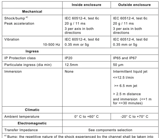
© Copyright PNO 2007 - All Rights Reserved Page 9 of 51 pages
Inside enclosure Outside enclosure
Mechanical
Shock/bump a) Peak acceleration
IEC 60512-4, test 6c 20 g / 11 ms 3 per axis in both directions
IEC 60512-4, test 6c 20 g / 11 ms 3 per axis in both directions Vibration 10-500 Hz IEC 60512-4, test 6d 0.35 mm or 5g IEC 60512-4, test 6d 0.35 mm or 5g Ingress
IP Protection class IP20 IP65 and IP67 Particulate ingress (dia min) 12.5mm 50 µm
Immersion None Intermittent liquid jet <=12.5 l/min >= 6.5 mm jet > 2.5 m distance and immersion (<=1 m for <=30 minutes) Climatic Ambient temperature 0° C to +60° C -20° C to +70° C Electromagnetic
Transfer Impedance See components selection
a) Bump: the repetitive nature of the shock experienced by the channel shall be taken into account.
Table 5.-1: General Environmental Requirements of passive PROFINET Connection Systems (informative Chart from IEC 61784-5-3 (CDV))
6 Connectors and cables for PROFINET
The PROFINET philosophy is to reduce the number of different connectors and in order to realise this, only the listed connectors shall be used for PROFINET networks. The use of these cables and
connectors represent a matched system with interoperability. The Connectors can be part of:
• Switch cabinet
• Device
• Cabling between devices
• Connections within a channel
• Controller • Industrial Outlet • Network Component • Sensor, Actuator • Drive, Motor • Coupling • …
© Copyright PNO 2007 - All Rights Reserved Page 10 of 51 pages
• PROFINET Data connectors and cabling
Only devices with the listed connectors fulfil the PROFINET specification and can be certified in a PROFINET test lab.
The integration of the 24 Volt power supply is referred as:
• SeparatePROFINET 24 Volt connectors and cabling
• PROFINET Hybrid connector and cabling
The listed different connectors are the preferred PROFINET solutions. Other connectors can be used for special applications.
The integration of the 400 Volt power supply is referred as:
• PROFINET 400 Volt connector and cabling
PROFINET refers to the Power distribution bus standardised in ISO 23570-3. Other connectors can be used for special applications.
© Copyright PNO 2007 - All Rights Reserved Page 11 of 51 pages
Table 6-2: PROFINET 24 Volt Connector overview
Figure 6-3: PROFINET 400 Volt Connector example
7 Procedure for a PROFINET Conformity Certificate
The conformity testing is only relevant for the PROFINET data connectors and cabling.
Connectors and cables shall fulfil the requirements and standards described in this guideline. To ensure the compatibility of cables and connectors under the PROFINET system, the cables and connectors shall be tested.
The Conformity certificate guarantees that the components have been tested as specified. All tests refer to the inside and outside requirements specified in this guideline. If the requirements are not covered by these environmental conditions, the vendor of the product has to be asked.
© Copyright PNO 2007 - All Rights Reserved Page 12 of 51 pages
Procedure for a
Conformity Certificate
Definition
of a cable and a connector combination
Test passed ? Test of cable and connector
Grant Conformity Certificate Yes No Conformity Certificate No
Figure: 7-1: Procedure for a Conformity Certificate
The vendor who issues the conformity certificate takes responsibility for the:
• listed cables and connectors or harnessed cables
• performing the test as specified in this guideline
• granting of the conformity certificate
The declaration can be issued unilaterally or bilaterally (e.g. from the cable and/or the connector vendor or the harness maker). Conformity testing is a requirement of PROFINET labelling of the products described in this guideline. The procedure for the declaration is a separate PI document.
The conformity declaration for the listed components is mandatory for PROFINET installation based on IEC 61784-5-3.
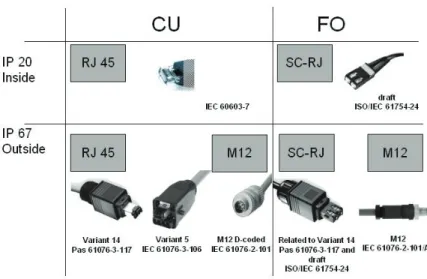
8 Connectors for PROFINET Data Cabling
8.1 Connectors for Inside Environment (Balanced Cabling)
8.1.1 Introduction
For the PROFINET Inside Environment one of the following connectors shall be used: a) RJ45 Connector, mating compatible to IEC 60603-7
© Copyright PNO 2007 - All Rights Reserved Page 13 of 51 pages
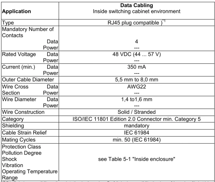
Data Cabling
Application
Inside switching cabinet environment
Type
RJ45 plug compatible )
*1Mandatory Number of
Contacts
Data
Power
---
4
Rated Voltage
Data
Power
48 VDC (44 ... 57 V)
---
Current (min.)
Data
Power
350 mA
---
Outer Cable Diameter
5,5 mm to 8,0 mm
Wire Cross
Section
Data
Power
AWG22
---
Wire Diameter
Data
Power
1,4 to1,6 mm
---
Wire Construction
Solid / Stranded
Category
ISO/IEC 11801 Edition 2.0 Connector min. Category 5
Shielding mandatory
Cable Strain Relief
IEC 61984
Mating Cycles
min. 50 (IEC 61984)
Protection Class
Pollution Degree
Shock
Vibration
Operating Temperature
Range
see Table 5-1 "Inside enclosure"
)*1 RJ-45 pinning compatibility applies only to the pins themselves. For full plug-in compatibility, the shape of the casing of industrial connectors shall also be taken into account. The specified RJ 45 receptacle (Jack) for
“Outside” applications has to be mating compatible with the RJ 45 Plug, in accordance with IEC 60 603-7.
Table 8-1: Plug Connector Specifications
The contact arrangement of the connectors and the colour coding of the cable is specified as follows:
Signal Function Wire Colours Contact Assignment RJ-45
TD + Transmit Data + Yellow 1 TD - Transmit Data - Orange 2 RD + Receive Data + White 3 RD - Receive Data - Blue 6
Table 8-2: Contact and Wire Assignment
The selected contact assignment of the RJ45 is compatible with the Ethernet standard, i.e. compatible with ISO/IEC 802-3. Four contacts are mandatory for PROFINET, a RJ 45 with eight contacts is also covered by this specification.
Only devices which are designed for use within a protected environment (e.g. Environment Inside) shall be designed with RJ45 connectors.
© Copyright PNO 2007 - All Rights Reserved Page 14 of 51 pages
8.1.2 The RJ 45 Connector
Selection of RJ45 plug connector products shall comply with the criteria for industrial machinery and equipment. The use of plug connectors with altered technical specifications (for example dielectric strength or connecting system) in comparison with those for office use is stipulated.
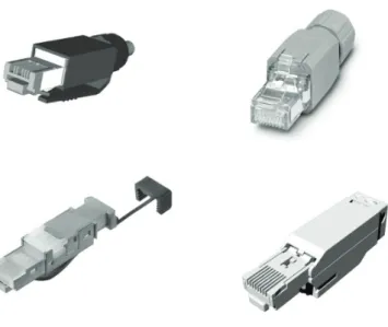
Figure 8.1.2-1: Examples of RJ45 Plugs in IP20 with Industrial Performance 8.1.2.1 Qualification Test for Copper Connectors (RJ45 IP20 Connectors)
The Qualification Test shall be performed in accordance with the following
standards:
© Copyright PNO 2007 - All Rights Reserved Page 15 of 51 pages IEC 60603-7(1996) mechanical structure of RJ45
IEC 60603-7-1(2002) introduction of shielding to RJ45 IEC 60603-7-3 (2007)
Connectors for electronic equipment - Part 7-3: Detail specification for 8-way, shielded, free and fixed connectors, for data transmissions with frequencies up to 100 MHz
IEC 60512-1-100, Connectors for electronic equipment – Tests and measurements – Part 1-100: General – Applicable publications
IEC 60352-4 (1994-09) Solderless connections - Part 4: Solderless non-accessible insulation displacement connections - General requirements, test methods and practical guidance
Additional test parameters are described in the Draft IEC 61784-5-3 and in Table 8-1: Plug Connector Specifications for Inside Applications (Data Cabling).
The plug for Inside Environment shall be pluggable to the jack in the protective housing specified in 8.2.2 to ensure reverse compatibility. An unprotected plug, which does not fulfil industrial requirements can be used exceptionally as part of diagnosis or commissioning.
8.2 Connectors for Outside Environment (Balanced cabling)
8.2.1 Introduction
For the PROFINET Outside Environment one of the following connectors shall be used: a) Connector variant 14, as defined in IEC PAS 61076-3-117 (further development of IEC
61076-3-106, variant 4) with RJ45 Connector as defined in IEC 60603-7
b) Connector variant 5, as defined in IEC 61076-3-106 with RJ45 Connector as defined in IEC 60603-7
c) M12 Connector “D” coded, as defined in IEC 61076-2-101-A1
One of these variants a, b,c shall be the connector at the AO, replacing the TO of IEC 24702. These connectors shall be used at all PROFINET devices conformance class.
© Copyright PNO 2007 - All Rights Reserved Page 16 of 51 pages
Data Cabling
Hybrid cabling
Application
Outside switching cabinet environment
Outside switching
cabinet environment
Type
RJ45 plug compatible )
*1or M12
RJ45 plug
compatible)
*1Mandatory Number of
Contacts
Data
Power
---
4
4
4
Rated Voltage
Data
Power
48 VDC (44 ... 57 V)
---
48 VDC (44 ... 57 V)
24 VDC (20,4 ... 28,8
V)
Current (min.)
Data
Power
350 mA
---
350 mA
16 A
Outer Cable Diameter
5,5 mm to 8,0 mm
6,0 mm to 12,0 mm
Wire Cross
Section
Power
Data
AWG 22
---
1,5 mm² to
AWG 22
2,5 mm²
Wire Diameter
Data
1,4 to 1,6 mm
1,4 to 1,6 mm
Wire Construction
Solid / Stranded
Transmission
Performance
ISO/IEC 11801 Edition 2.0 Class D
Category (min.)
ISO/IEC 11801 Edition 2.0 Connector Category 5
Shielding Yes
Cable Strain Relief
IEC 61984
Mating Cycles
min. 50
Protection Class
Pollution Degree
Shock
Vibration
Operating Temperature
Range
see Table 5-1 "Outside enclosure"
)*1 RJ-45 pinning compatibility applies only to the pins themselves. For full plug-in compatibility, the shape of the casing of industrial connectors shall also be taken into account . The specified RJ 45 receptacle (Jack) for
“Outside” applications has to be mating compatible with the RJ 45 Plug, in accordance with IEC 60 603-7.
Table 8-3: Plug Connector Specifications
© Copyright PNO 2007 - All Rights Reserved Page 17 of 51 pages The contact arrangement of the connectors and the colour coding of the cable is specified as follows:
Signal Function Wire Colours Contact Assignment RJ 45 M12
TD + Transmit Data + Yellow 1 1 TD - Transmit Data - Orange 2 3 RD + Receive Data + White 3 2 RD - Receive Data - Blue 6 4
Table 8-4: Contact and Wire Assignment
The selected contact assignment of the RJ45 is compatible with the Ethernet standard, i.e. compatible with ISO/IEC 802-3. Four contacts are mandatory for PROFINET, a RJ 45 with eight contacts is also covered by this specification.
For IP65/67 field devices either a RJ45 or a M12-based solution is possible, depending on the application.
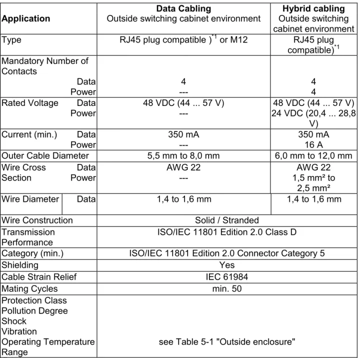
8.2.2 RJ45 IP67 Connector
Standardised RJ45-compatible IP67-plug connectors shall be used and the protective housing is described in the following standard:
IEC PAS 61076-3-117
Figure 8.2.2-1: Examples of IP67 RJ45 Plug Connector
8.2.2.1 Qualification Test for Copper Connectors (RJ 45 Based IP 67 Connectors)
The Qualification Test shall be performed in accordance with the following standards:
IEC PAS 61076-3-117
Additional test parameters are described in the IEC 61784-5-3 (Draft).
Installation Guideline Table 8-3: Plug Connector Specifications for Outside Applications (Data Cabling and Hybrid Cabling).
© Copyright PNO 2007 - All Rights Reserved Page 18 of 51 pages
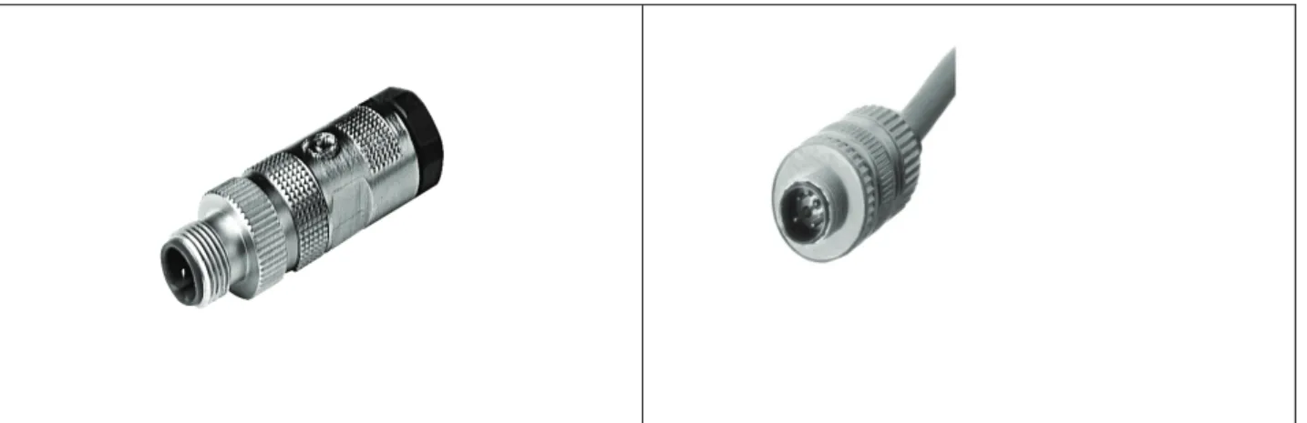
8.2.3 M12 Connectors
Standardised M12 connectors (IP65/67 or higher) shall be used and are described in the following standard:
IEC 61076-2-101/A1
Figure 8.2.3-1: Examples of M12 Plug Connector with “D”-Coding
A 4-pin plug connector with “D“ coding for Industrial Ethernet shall be applicable for all connection and transmission wires. Devices shall be fitted with the appropriate sockets.
For contact and wire assignment see Figure 8.2.3-2.
male
female
© Copyright PNO 2007 - All Rights Reserved Page 19 of 51 pages “D” coding shall be used and contact chamber 5 of an appliance socket shall be closed.
This makes it virtually impossible to plug the M12 PROFINET connector incorrectly into previously installed field buses.
The dimensions of the plug connector shall comply with the above mentioned standards.
8.2.3.1 Qualification Test for Copper Connectors (M12 Connector)
The Qualification Test shall be performed in accordance with the following standards:
IEC 61076-2-101/A1
Additional test parameters are described in the Draft IEC 61784-5-x Profile 3/3
Installation Guideline Table 7-1: Plug Connector Specifications for Outside Applications (Data Cabling).
8.2.4 Connectors for Hybrid Cabling
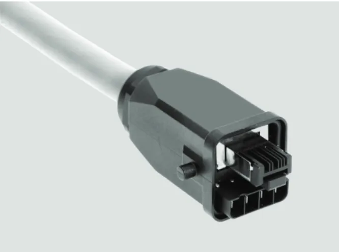
Standardised RJ45-compatible IP67 plug connectors shall be used and are described in the following standard: IEC 61076-3-106 – RJ 45 - Industrial RJ45 Variant 05
Figure 8.2.4-1: Picture of a Hybrid Plug Connector
The hybrid plug connector is to be used where decentralized field devices are to be connected via one combined plug connector for data and power supply. A complete contact-protected plug connector enables the use of the same plug connectors at both ends because no pin-socket change is necessary.
8.2.4.1 Qualification Test for Hybrid Connectors (RJ 45 Based IP 67 Connectors) The Qualification Test shall be performed in accordance with the following standards:
IEC 61076-3-106
© Copyright PNO 2007 - All Rights Reserved Page 20 of 51 pages Installation Guideline Table 7-1: Plug Connector Specifications for Outside Applications (Data Cabling and Hybrid Cabling).
8.3 Connectors for inside environment (optical fibre)
8.3.1 Introduction
The connection of optical fibre cables and device or optical fibre cables with each other shall be made with a SC-RJ connector system.
Socket type connections must be used for appliance and information-system connections. Connecting cables (unit connection cable, equipment cable, patch cords) must be fitted accordingly with plugs at both ends.
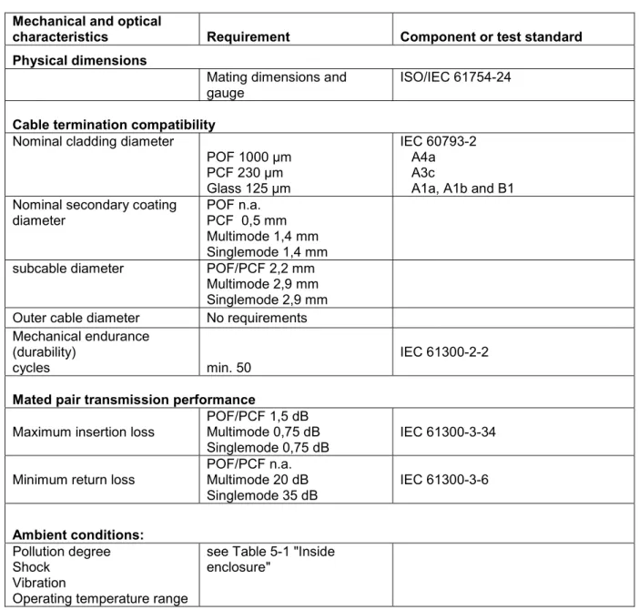
Mechanical and optical
characteristics Requirement Component or test standard Physical dimensions
Mating dimensions and
gauge ISO/IEC 61754-24
Cable termination compatibility
Nominal cladding diameter
POF 1000 µm PCF 230 µm Glass 125 µm IEC 60793-2 A4a A3c
A1a, A1b and B1 Nominal secondary coating
diameter POF n.a. PCF 0,5 mm Multimode 1,4 mm Singlemode 1,4 mm subcable diameter POF/PCF 2,2 mm
Multimode 2,9 mm Singlemode 2,9 mm Outer cable diameter No requirements Mechanical endurance
(durability)
cycles min. 50 IEC 61300-2-2
Mated pair transmission performance
Maximum insertion loss POF/PCF 1,5 dB Multimode 0,75 dB Singlemode 0,75 dB
IEC 61300-3-34 Minimum return loss POF/PCF n.a. Multimode 20 dB
Singlemode 35 dB IEC 61300-3-6
Ambient conditions:
Pollution degree Shock
Vibration
Operating temperature range
see Table 5-1 "Inside enclosure"
Table 8.3.1-1 – Mechanical and optical characteristics of optical fibre connecting hardware for “inside” environment
© Copyright PNO 2007 - All Rights Reserved Page 21 of 51 pages
8.3.2 SC-RJ Connector
8.3.2.1 Specification of SC-RJ Connector
The SC-RJ Connector is the main connector for PROFINET fibre connections. The connector is prescribed in EN 50377-6-1, ISO/IEC 61754-24(draft).
PROFINET requirements are shown in Table 8.3.1-1.
Figure 8.3.2-1: SC-RJ Connector
8.3.2.2 Qualification test of SC-RJ Connector
The connector under test shall be terminated onto PROFINET optical fibre cable as specified in clause 9.2. of this guideline.
A full set of tests as specified in ISO/IEC 61753-series shall be carried out for all fibre types for which PROFINET compliance is claimed. The test load of each test shall meet ISO/IEC 61753 or PROFINET requirements of Table 8.3.1-1 which ever is severe.
All test methods shall be in accordance with the IEC 61300 series of standards.
8.3.3 Additonal Fibre connectors for existing installations
Optical fibre connector types BFOC/2.5 (IEC 60874-10) and SC-Duplex (in IEC 60874-14) may be used as an additional alternative to connect existing installations. Both connector types are not recommended for new designs.The connectors used shall also meet IEC 61753, Category C and PROFINET
© Copyright PNO 2007 - All Rights Reserved Page 22 of 51 pages
8.4 Connectors for outside environment (optical fibre)
8.4.1 Introduction
The connection of optical fibre cables and device or optical fibre cables with each other shall be made with the SC-RJ Push Pull OF connector system or with M12 OF connector system.
Socket type connections must be used for appliance and information-system connections. Connecting cables (unit connection cable, equipment cable, patch cords) must be fitted accordingly with plugs at both ends.
Mechanical and optical
characteristics Requirement Component or test standard Physical dimensions
Mating dimensions and
gauging SC-RJ Push Pull OF connector M12 OF connector ISO/IEC 61754-24-2 (draft) In preparation
Cable termination compatibility
Nominal cladding diameter
POF 1000 µm PCF 230 µm Glass 125 µm IEC 60793-2 A4a A3c
A1a, A1b and B1 Nominal secondary coating
diameter POF n.a. PCF 0,5 mm Multimode 1,4 mm Singlemode 1,4 mm subcable diameter POF/PCF 2,2 mm
Multimode 2,9 mm Singlemode 2,9 mm Outer cable diameter Max. 9,5 mm Mechanical endurance
(durability)
cycles ≥50
IEC 61300-2-2
Mated pair transmission performance
Maximum insertion loss POF/PCF 1,5 dB Multimode 0,75 dB Singlemode 0,75 dB
IEC 61300-3-34 Minimum return loss POF/PCF n.a. Multimode 20 dB
Singlemode 35 dB IEC 61300-3-6
Ambient conditions:
Pollution degree Shock
Vibration
Operating temperature range
see Table 5-1 "Outside enclosure"
Table 8.4.1-1 – Mechanical and optical characteristics of optical fibre connecting hardware for “outside” environment
© Copyright PNO 2007 - All Rights Reserved Page 23 of 51 pages
8.4.2 SC-RJ Push Pull OF connector
8.4.2.1 Specification of Push Pull OF Connector
The SC-RJ connector with push pull housing is the main connector in harsh environments for PROFINET optical fibre connections and offers a universal system in conjunction with the IP20 environment. The connector is prescribed ISO/IEC 61754-24-2 (draft).
The SC-RJ Push Pull OF connector is shown in Figure 8.4.2-1; dimensions are for orientation only.
PROFINET requirements are shown in Table 8.4.1-1.
Figure 8.4.2-1: SC-RJ Connector with push Pull housing
8.4.2.2 Qualification test of Push Pull OF connector
The connector under test shall be terminated onto PROFINET optical fibre cable as specified in clause 9.2. of this guideline.
A full set of tests as specified in the ISO/IEC 61753-series shall be carried out for all fibre types for which PROFINET compliance is claimed. The test load of each test shall meet either ISO/IEC 61753 or the PROFINET requirements in Table 8.4.1-1 which ever is more severe.
All test methods shall be in accordance with the IEC 61300 series of standards.
8.4.3 M12 OF connector
8.4.3.1 Specification of M12 OF connector
The M12 OF connector is a compact miniature OF connector based on the proven M12 design (standard in preparation). It is applicable for plastic, plastic clad silica, multimode and singlemode optical fibre.
© Copyright PNO 2007 - All Rights Reserved Page 24 of 51 pages
Contact type SM MM POF PCF
D : ferrule contact diameter 1.25 mm 1.25 mm 1.59 mm 1.59 mm
Figure 8.4.3-1: M12 OF Connector
8.4.3.2 Qualification test of M12 OF connector
The connector under test shall be terminated onto PROFINET optical fibre cable as specified in clause 9.2 of this guideline.
A full set of tests as specified in the ISO/IEC 61753-series shall be carried out for all fibre types for which PROFINET compliance is claimed. The test load of each test shall meet either ISO/IEC 61753 or the PROFINET requirements in Table 8.4.1-1 which ever is more severe.
All test methods shall be in accordance with the IEC 61300 series of standards.
9 Cables for PROFINET Data Cabling
9.1 Balanced Cables
9.1.1 Balanced Cables (Type A,B,C)
PROFINET cables used are based electrically on category 5 balanced LAN cables according to ISO/IEC 11801 Edition 2.0.Class D.
In special applications (e.g. the use of trailing cables and frequently moved machine parts), cables are permitted whose design and mechanical parameters can deviate from the specifications of type A and type B cable (see Table 9.1-1), while retaining most of the electrical parameters (impedance levels etc.). These cables are type C cables. Highly flexible copper cables generally have the finest stranded
conductors and, for example, a highly resistant polyurethane outer sheath.
Various outer sheath materials are permitted in order to meet the various demands with regard to resistance of industrial environments and exterior/underground laying (natural and synthetic oil, grease, coolants/lubricants, chemicals, high and low temperatures, UV radiation).
Industrial-type plug connectors type RJ45, protection type IP67, or a tried and tested industrial round plug connector M12, category 5, are to be used as plug connectors.
All balanced cables used shall comply with the following parameters: Standard M12 Thread
© Copyright PNO 2007 - All Rights Reserved Page 25 of 51 pages
Cable Type
Application Type
A
Application Type
B
Application Type
C
Design
Data Cable
Data Cable
Data Cable
Cable Installation Type
Stationary, no
movement after
installation
Flexible,
occasional
movement or
vibration
Special
Applications (e.g.
highly flexible,
permanent
movement,
vibration or
torsion)
System Concept:
Cable Marking
(at least)
PROFINET Type
A
PROFINET Type
B
PROFINET Type
C
Core Cross Section
AWG 22/1
AWG 22/7
AWG 22/..
Outer Cable Diameter
5,5 - 8,0 mm
Application
Core Diameter
1,5 +/- 0,1 mm
Application
Colour (Outer Sheath)
Green RAL6018
Application
Core Identification
(colours)
star quad
2 pair
white, yellow, blue, orange
Pair 1: white (RXD+), blue (RXD-)
Pair 2: yellow(TXD+), orange(TXT-)
Number of Cores
4
© Copyright PNO 2007 - All Rights Reserved Page 26 of 51 pages
Shielding Design Type
Aluminum Foil + Copper Braiding
Application
Which Plug for which
Cable Type
RJ45 (IP 20 or IP 65/67) / M12
Transmission Performance Requirements:
Relevant Standard
ISO/IEC 11801 Edition 2.0, IEC 61156
(minimum Category 5)
Delay Skew:
<=20ns/100m
Transfer Impedance
<=50 m
Ω
/m at 10 MHz
Ambient Conditions:
Minimum Tensile
strength
50 N
Maximum Lateral forces
3000 N IEC
61156-1 3.4.6
61156-1 3.4.6
3000 N IEC
Application
Pollution Degree
Shock
Vibration
Operating Temperature
Range
see Table 5-1 "Outside enclosure"
Table 9.1-1: Balanced Cable Specification
The wire assignment of the star-quad cable is indicated by the following colour coding:
white
yellow
blue orange
Figure 9.1-1: Wire Assignment of Star-Quad Cables
The following parameters shall preferably adhered to:
• Sheathing materials suitable for the intended application
• Flame retardance in accordance with IEC 60332-1
• Materials for special applications materials free of substances destructive to lacquer-coatings (e.g. silicone)
© Copyright PNO 2007 - All Rights Reserved Page 27 of 51 pages
9.1.2 Balanced Hybrid Cables (Type B,C)
Hybrid cables contain wires for signals and voltage supply.
•
Cu/Cu design (4 wire data transmission / 4 wire for power transmission).Cable Type
Application Type B
Application Type C
Design
Hybrid Cable
Hybrid Cable
Cable Installation Type
Flexible, occasional
movement or vibration
Special Applications
(e.g. highly flexible,
permanent movement,
vibration or torsion)
System Concept:
Number of Wires
Data
Power
4
4
4
4
Core Cross Section
Data
Power
AWG 22/7
1,5 mm
2AWG 22/..
1,5 mm
2Cable Marking
(at least)
PROFINET Hybrid Type
B
PROFINET Hybrid Type
C
Outer Cable Diameter
8,0 ... 12,0 mm
Core Diameter
Data
Power
1,5 +/- 0,1 mm
2,4+/-0,2mm
Application Specific
Colour (Outer Sheath)
Green RAL6018
Application Specific
Core Identification
(Colours)
Star Quad
2 Pair
Power
White, Yellow, Blue, Orange
Pair 1: White, Blue
Pair 2: Yellow, Orange
Black with numbers 1,2,3,4
Cable Design
2 pairs or 1 star quad
+ 4 power wires
Screening Design Type Aluminium Foil + Copper Braiding
(Data Wires)
Which Plug for which
Cable Type
RJ45 (hybrid)
Transmission Performance Requirements (Data Wires):
Relevant Standard
ISO/IEC 11801 Edition 2.0, IEC 61156
(minimum Category 5)
Delay Skew:
<=20ns/100m
Transfer Impedance
<=50 m
Ω
/m bei 10 MHz
© Copyright PNO 2007 - All Rights Reserved Page 28 of 51 pages
Minimum Tensile
strength
50 N
Application
Specific
Maximum Lateral forces
3000 N IEC
61156-1 3.4.6
3000 N IEC
61156-1 3.4.6
Application
Pollution Degree
Shock
Vibration
Operating Temperature
Range
See Table 5-1 "Outside enclosure"
Maximal Current in each
Power-Wire:
For T<=55°C: 16A
For T>55°C the current is not specified but may be
indicated in the relevant detailed specification of the
cable manufacturer (derating diagram)
Table 9.2-1: Hybrid Wire Cable Specification
Note:
The possible channel length of the hybrid cable depends on the power consumption of the connected devices.
9.1.2.1 Qualification test for PROFINET copper-cables
The Qualification Test shall be performed in accordance with the following standards: IEC 61156-5 (2002) Symmetrical pair/quad cables with transmission characteristics up to 600MHz -Horicontal floor wiring - Sectional Specification
IEC 61156-6 (2002) Symmetrical pair/quad cables with transmission characteristics up to 600MHz- Work area wiring - Sectional Specification
ISO/IEC 11801 (2002): Generic cabling
IEC 60189-1 (1986) Low-frequency cables and wires with PVC insulation and PVC sheath. Part 1: General test and measuring methods
IEC 60332 – 1(1993): Tests on electric cables under fire conditions - Part 1: Test on a single vertical insulated wire or cable
IEC 60811-1-1(2001): Part 1-1: Methods for general application - Measurement of thickness and overall dimensions - Tests for determining the mechanical properties
IEC 60811-1-2 (1985): Part 1: Methods for general application - Section Two: Thermal ageing methods
IEC 60811-3-1(1985): Part 3: Methods specific to PVC compounds - Section One: Pressure test at high temperature - Tests for resistance to cracking
Test requirement are defined in the following table:
Cable
Type to be
tested
Test-Title
Severity or
condition of
test
Measuremen
t to be
preformed
Requirements
Type A
and B
IEC 11801 cat 5
component
Category 5 IEC 61156-5 Electrical
requirement
category 5
Hybrid
IEC 11801 cat 5
Category 5 IEC 61156-5 Electrical
© Copyright PNO 2007 - All Rights Reserved Page 29 of 51 pages
Type B
component
requirement
category 5
Type C
IEC 11801 cat 5
component
Category 5
IEC 61156-6 Electrical
requirement
category 5
Hybrid
Type C
IEC 11801 cat 5
component
Category 5
IEC 61156-6 Electrical
requirement
category 5
Type A
and C
Conductor
resistance
AWG 22
IEC 60189-1 <= 62
Ω
/km
Type B
Conductor
resistance
AWG 22/7
IEC 60189-1 <= 60
Ω
/km
Type A
and B
Screening
attenuation
For Grade 1 IEC
61156-5 : 3.3.8
>= 60 dB
Type A
and B
Elongation at break
of the insulation
IEC
60811-1-1
IEC 61156-5
Type A
and B
Elongation at break
of the sheat
IEC
1-1
60811-
IEC 61156-5
Type A
and B
Elongation at break
of the sheat after
ageing
IEC
60811-1-2
IEC 61156-5
Type A
and B
Tensile strength of
the sheat
IEC
60811-1-1
IEC 61156-5
Type A
and B
Tensile strength of
the sheat after
ageing
IEC
60811-1-2
IEC 61156-5
Type A
and B
Maximum Lateral
Forces
IEC
61156-1
3.4.6
3000 N
Type A
and B
Flame retardant
IEC 60332 -
1
Has to pass the
test
Type A
and B
Sheath pressure test
at high temperature
IEC
3-1
60811-
Max. 50 %
Type A
and B
Heat shock test
IEC
60811-3-1
No cracks
Type A, B Core diameter
1,5 +/- 0,1
mm
IEC
60811-1-1
>=1,4 mm,
<=1,6 mm
Type A, B Outer cable diameter 5,5 mm – 8,0
mm
IEC
60811-1-1
>=5,5 mm,
<=8,0mm
Hybrid
Type B
Conductor
resistance Datawire
AWG 22/7
IEC 60189-1 <= 60
Ω
/km
Hybrid
Type B
Flame retardant
IEC 60332 -
1
Has to pass the
test
Hybrid
Type B
Sheath pressure test
at high temperature
IEC 60811-
3-1
Max. 50 %
Hybrid
Type B
Heat shock test
IEC 60811-
3-1
No cracks
Hybrid
Type B
Screening
attenuation
For Grade 1 IEC
61156-5 : 3.3.8
>= 60 dB
Hybrid
Type C
Conductor
resistance Datawire
AWG 22
IEC 60189-1 <= 62
Ω
/km
© Copyright PNO 2007 - All Rights Reserved Page 30 of 51 pages
Hybrid
Type B
and C
Conductor
resistance
Powerwire
>=1,5 mm²
IEC 60189-1 <= 14
Ω
/km
Hybrid
Type B
and C
Core diameter
Datawire
1,5 +/- 0,1
mm
IEC
60811-1-1
>=1,4 mm,
<=1,6 mm
Hybrid
Type B
and C
Outer cable diameter 8.0 mm –
12,0 mm
IEC 60811-
1-1
>=8,0 mm,
<=12,0mm
Type A, B
and Hybrid
Type B
Minimum tensile
strengths
50 N
EN 50 289-
3-16 (2002)
IEC 61 156-5
All
Colour outer Jacket green
Visual
inspection
RAL 6018
All Colour
Datawire
White,
yellow, blue,
orange
Visual
inspection
IEC 61784-5-x
and
this PROFINET
Guideline
All Transfer
impedance
<=
50mOhm/m
at 10 MHZ
IEC
61156-5 : 3.2.7
<= 50mOhm/m at
10 MHZ
All Operating
temperature
-
20°C...+70°C
All
have to designed
cable
material
for -20°C...+70°C
All Differential
delay
/
Delay skew
IEC
61156-5
<=20ns/100m
Table 9.2.1-1: Test requirement Balanced Cables
9.2 Optical fibre cables (POF, PCF, multimode, singlemode)
9.2.1 Introduction
PROFINET provides optical fibre cables with four types of optical fibre:
• Plastic optical fibre (POF)
• Plastic clad silica optical fibre (PCF)
• All-silica multimode fibre
• All-silica singlemode fibre
The cable design depends on application requirements and classified into two groups:
• Type B optical fibre cable for stationary or flexible use
• Type C optical fibre cable
for special applications e.g. with permanent movement or vibration or torsion All cable constructions (Type B and C) include two fibre elements.
© Copyright PNO 2007 - All Rights Reserved Page 31 of 51 pages
9.2.2 POF and PCF cables
9.2.2.1 Specification of POF and PCF cables
Plastic optical fibre (POF) and Polymer clad fibre (PCF) cables shall comply with the requirements listed in Table 9.2.2.1-1. For more information see technical specification “Physical Layer Medium Dependent Sublayer on 650 nm Fibre Optics”, PI order no. 2.432.
Cable type Plastic optical fibre
and polymer clad fibre cables
Design data cable data cable
Cable installation type stationary, flexible, depending on cable construction
highly flexible, permanent movement or vibration or torsion (special
applications)
System concept:
Cable marking
(at least) i.e.: PROFINET Type B 2P980/1000 PROFINET Type B + fibre type PROFINET Type B 2K200/230
PROFINET Type C + fibre type
i.e.: PROFINET Type C 2P980/1000 PROFINET Type C 2K200/230
Outer cable diameter
(cables for use with IP20 connections)
no requirements no requirements
Outer cable diameter
(cables for use with PROFINET IP65/67 connectors)
max. 9,5 mm max. 9,5 mm
Diameter secondary coating POF: n.a.
PCF: 0,5 mm PCF: 0,5 mm POF: n.a.
Diameter subcable 2,2 mm 2,2 mm
Colour (outer sheath) green RAL6018 depending on the application )*1
Colours (subcable) orange + black
orange with arrow (pointing direction of data stream)
orange + black
orange with arrow (pointing direction of data stream)
Number of fibres 2 2
Ambient conditions:
Minimum tensile strength (cable, long term)
POF: 100 N
PCF: 400 N depending on the application )
*1
Bending radius
static long term > 15 times cable diameter depending on the application )
*1
Pollution degree Shock
Vibration
Operating temperature range
see Table 5-1 "Outside enclosure" depending on the application )*1
Transmission performance requirements:
Relevant standard IEC 60793-2
Type (according to IEC 60793-2) POF: A4a
PCF: A3c
Core/cladding diameter POF: 980/ 1000 µm
PCF: 200/230 µm Nominal wavelength 650 nm Bandwidth MHz referred to 100 m @650 nm; launch NA = 0,5 POF: >=35 MHz PCF: >=70 MHz Maximum attenuation
@650 nm; FWHM < 4 nm POF: 160 dB/km PCF: 10 dB/km POF: depending on the application)
*1
PCF: 10 dB/km
Numerical aperture POF: 0,50 +/-0,05
PCF: 0,37 +/-0,04
)*1 for type C cables refer to manufacturers data sheet
© Copyright PNO 2007 - All Rights Reserved Page 32 of 51 pages
9.2.2.2 Qualification test for POF and PCF cables
The PROFINET qualification Test for Plastic optical fibre (POF) and Polymer clad fibre (PCF) cables shall be performed in accordance with Table 9.2.2.1-1
Cable type POF and PCF cables
Characteristics Test Standard Requirements
Cable installation type
stationary, flexible, depending on cable construction
(type B cable)
highly flexible, permanent movement or vibration or torsion
(special applications) (type C cable) Outer cable diameter
(cables for use with PROFINET IP65/67
connectors) IEC 60811-1-1 max. 9,5 mm max. 9,5 mm Diameter secondary coating
PCF IEC 60811-1-1 0,50 +/- 0,05 mm 0,50 +/- 0,05 mm Diameter subcable POF IEC 60811-1-1 2,2 +/- 0,1 mm 2,2 +/- 0,1 mm
Diameter subcable PCF IEC 60811-1-1 2,2 +/- 0,1 mm 2,2 +/- 0,1 mm
Minimum tensile strength POF
IEC 60794-1-2, Methode E1
100 N; 45 m length;
max. 1 dB Δ A (@ 650 nm) depending on the application Minimum tensile strength PCF
IEC 60794-1-2, Methode E1
400 N; 100 m length;
max. 1 dB Δ A (@ 650 nm) depending on the application
Bending radius
IEC 60794-1-2, Methode E11A
Bending radius 15 times cable diameter, 5 turns, 1 cycle,
max. 1,0 dB (@ 650 nm) depending on the application
Operating temperature range
PCF IEC 60794-1-2, Methode F1 2 cycles -20°C / +70°C; tmax. 1,5 dB / 100 m (@ 650 nm) 1=24h; depending on the application
Operating temperature range POF
IEC 60794-1-2, Methode F1
2 cycles -20°C / +70°C; t1=24h;
max. 2,5 dB/50 m (@ 650 nm) depending on the application Bandwidth MHz referred to 100 m @650 nm; launch NA = 0,5 IEC 60793-1-41 POF: >=35 MHz; PCF: >=70 MHz POF: >=35 MHz; PCF: >=70 MHz Maximum attenuation @650 nm; FWHM < 4 nm IEC 60793-1-40 POF: max. 160 dB/km; PCF: max. 10 dB/km POF: max. 180 dB/km; PCF: max. 10 dB/km
Numerical aperture IEC 60793-1-20
POF: 0,50 +/-0,05; PCF: 0,37 +/-0,04
POF: 0,50 +/-0,05; PCF: 0,37 +/-0,04
© Copyright PNO 2007 - All Rights Reserved Page 33 of 51 pages
9.2.3 All-silica multimode optical fibre cables
9.2.3.1 Specification of all-silica multimode optical fibre cables
All-silica multimode optical fibre cables shall comply with the requirements listed in Table 9.2.3.1-1.
Cable type All-silica multimode optical fibre cables
Design data cable data cable
Cable installation type stationary, flexible, depending on cable construction
(type B cable)
highly flexible, permanent movement or vibration or torsion (special
applications) (type C cable)
System concept:
Cable marking
(at least) PROFINET Type B + fibre typei.e.: PROFINET Type B 2G50/125 PROFINET Type B 2G62,5/125
PROFINET Type C + fibre type
i.e.: PROFINET Type C 2G50/125 PROFINET Type C 2G62,5/125
Outer cable diameter
(cables for use with IP20 connections) No requirements No requirements
Outer cable diameter
(cables for use with PROFINET IP65/67 connectors)
max. 9,5 mm max. 9,5 mm
Diameter secondary coating 1,4 mm 1,4 mm
Diameter subcable 2,9 mm 2,9 mm
Colour (outer sheath) green RAL6018 depending on the application )*3 Colours (subcable) orange + black
orange with arrow (pointing direction of data stream)
orange + black
orange with arrow (pointing direction of data stream)
Number of fibres 2 2
Ambient conditions:
Minimum tensile strength 600 N depending on the application )*3 Bending radius (static long
term) > 15 times cable diameter )
*2 depending on the application )*3
Pollution degree Shock
Vibration
Operating temperature range
see Table 5-1 "Outside
enclosure" depending on the application )*3
Transmission performance requirements:
Relevant standard IEC 60793-2
Type
according to IEC 60793-2 A1a , A1b
Core/cladding diameter 50/125 µm 62,5/125 µm Nominal wavelength 1300 nm Bandwidth MHz referred to 1 km >=500 MHz )*1 Maximum attenuation 1,5 dB/km )*1
)*1 measured in accordance with IEC 60793-1-40 and IEC 60793-1-41
)*2 Deviating bending radius are possible according to manufacturer's specifications. )*3 for type C cables refer to manufacturers data sheet
Table 9.2.3.1-1: Requirements for all-silica multimode optical fibre cables
© Copyright PNO 2007 - All Rights Reserved Page 34 of 51 pages
9.2.3.2 Qualification test of all-silica multimode optical fibre cables
The PROFINET qualification test of all-silica multimode optical fibre cables shall be performed in accordance with Table 9.2.3.2-1.
Cable type All-silica multimode optical fibre cables
Characteristics Test Standard Requirements
Cable installation type
stationary, flexible, depending on cable construction
(type B cable)
highly flexible, permanent movement or vibration or torsion
(special applications) (type C cable) Outer cable diameter
(cables for use with PROFINET
IP65/67 connectors) IEC 60811-1-1 max. 9,5 mm depending on the application Diameter secondary coating IEC 60811-1-1 1,4 +/- 0,1 mm 1,4 +/- 0,1 mm
Diameter subcable IEC 60811-1-1 2,9 +/- 0,1 mm 2,9 +/- 0,1 mm
Minimum tensile strength IEC 60794-1-2, Methode E1 600 N; 100 m length; max. 1,0 dB Δ A (@ 1300 nm) depending on the application
Bending radius
IEC 60794-1-2, Methode E11A
Bending radius 10 times cable diameter, 5 turns, 1 cycle,
max. 0,1 dB (@ 1300 nm) depending on the application
Operating temperature range
IEC 60794-1-2, Methode F1 2 cycles -20°C / +70°C; t1=24h; max. 1,0 dB/km (@ 1300 nm) 2 cycles -20°C / +70°C; t1=24h; max. 1,0 dB/km (@ 1300 nm) Bandwidth MHz referred to 1 km @1300 nm IEC 60793-1-41 >=500 MHz >=500 MHz Maximum attenuation
@1300 nm IEC 60793-1-40 max. 1,5 dB/km max. 1,5 dB/km
© Copyright PNO 2007 - All Rights Reserved Page 35 of 51 pages
9.2.4 All-silica singlemode optical fibre cables
9.2.4.1 Specification of all-silica singlemode optical fibre cables
All-silica singlemode optical fibre cables shall comply with the requirements listed in Table 9.2.4.1-1.
Cable type All-silica singlemode optical fibre cables
Design data cable data cable
Cable installation type stationary, flexible depending on cable construction
(type B cable)
highly flexible, permanent movement or vibration or torsion
(special applications) (type C cable)
System concept:
Cable marking (at least)
PROFINET Type B + fibre type
i.e.: PROFINET Type B 2E9/125
PROFINET Type C + fibre type
i.e.: PROFINET Type C 2E9/125
Outer cable diameter max. 9,5 mm depending on the application )*3
Diameter secondary coating 1,4 mm 1,4 mm
Diameter subcable 2,9 mm 2,9 mm
Colour (outer sheath) green RAL6018 depending on the application )*3
Colours (subcable) orange + black
orange with arrow (pointing direction of data stream)
orange + black
orange with arrow (pointing direction of data stream)
Number of fibres 2 2
Ambient conditions:
Minimum tensile strength
(cable, long term) 600 N depending on the application )*
3
Bending radius (Static long term) > 15 times cable diameter depending on the application )*3 Pollution degree
Shock Vibration
Operating temperature range
see Table 5-1 "Outside enclosure"
depending on the application )*3
Transmission performance requirements:
Relevant standard IEC 60793-2
Type (according to IEC 60793-2) B1
Cladding diameter 125 µm ±2 µm Nominal wavelength 1300nm Maximum attenuation (at 1310 nm) 0,5 dB/km )* 2 Cut-off wavelength < 1260 nm )*1 )*1 according IEC 60793-1-44 )*2 according IEC60793-1-40
)*3 for type C cables refer to manufacturers data sheet
© Copyright PNO 2007 - All Rights Reserved Page 36 of 51 pages
9.2.4.2 Qualifikation test of all-silica singlemode optical fibre cables
The PROFINET qualification test of all-silica singlemode optical fibre cables shall be performed in accordance with Table 9.2.4.1-1.
Cable type All-silica singlemode optical fibre cables
Characteristics Test Standard Requirements
Cable installation type
stationary, flexible, depending on cable construction
(type B cable)
highly flexible, permanent movement or vibration or torsion
(special applications) (type C cable)
Outer cable diameter
(cables for use with PROFINET
IP65/67 connectors) IEC 60811-1-1 max. 9,5 mm depending on the application
Diameter secondary coating IEC 60811-1-1 1,4 +/- 0,1 mm 1,4 +/- 0,1 mm
Diameter subcable IEC 60811-1-1 2,9 +/- 0,1 mm 2,9 +/- 0,1 mm
Minimum tensile strength
IEC 60794-1-2, Methode E1
600 N; 100 m length;
max. 1,0 dB Δ A (@ 1300 nm) depending on the application
Bending radius
IEC 60794-1-2, Methode E11A
Bending radius 10 times cable diameter, 5 turns, 1 cycle,
max. 0,1 dB (@ 1300 nm) depending on the application
Operating temperature range
IEC 60794-1-2, Methode F1
2 cycles -20°C / +70°C; t1=24h;
max. 1,0 dB/km (@ 1300 nm) depending on the application Maximum attenuation
@1300 nm IEC 60793-1-40 1,0 dB/km 1,0 dB/km Cut-off wavelength IEC 60793-1-44 < 1260 nm < 1260 nm
© Copyright PNO 2007 - All Rights Reserved Page 37 of 51 pages
10 Cord Sets for PROFINET Data Cabling
10.1 Cord Sets for Balanced Cabling
Cord Sets are harnessed cables. PROFINET cords that meet the requirement are described in the following Figure 10.1-2.
TE,
PMD
TE,
PMD
Cord set 1 Cord set 2 Cord set 3
Channel build up from cord sets
BulkheadFigure 10.1-2: Channel definition
Cross-Over:
A cross-over changes the signal over from transmitter to receiver and is realised inside the device and not in the cabling.
© Copyright PNO 2007 - All Rights Reserved Page 38 of 51 pages
Figure 10.1-1: Cable Connection
PROFINET cord sets consist of a PROFINET conform cable harnessed with a PROFINET conform connector .Only connectors and cables specified in this Guideline shall be used. In addition to the component test it is necessary to fulfil the requirements for cord sets. Connecting hardware performance is influenced by the properties of the plug
termination and, therefore cords should be tested to determine the quality of the assembly. This clause specifies the minimum requirements for cords. The test methods and mechanical stresses are specified in IEC 61935-2. All requirements of this clause have to be met after first exposing the device under test to mechanical stress. Cords shall meet the electrical and mechanical requirements of IEC 61935-2.
Referring the specification in IEC 11801, values of this cord sets are comparable to patch cords. In 11801 these cables are not those specified for the horizontal link. Longer cord sets are possible but shall not labelled as PROFINET cord sets, also the components are all PROFINET conform.
NEXT
Frequency MHz dB Length 2 m 5 m 10 m >10 m 1 65,00 65,00 65,00 65,00 16 50,30 49,50 48,70 48,70 100 35,00 34,70 34,50 34,50Table 10.1-2: Values of NEXT at key frequencies for PROFINET cord sets
10.1.1 Cord Sets for Balanced Type A/B Cabling
Cords shall meet return loss (RL) and Next requirements specified in IEC 11801. Insertion loss (IL) of cord sets shall not exceed the value stated for the given length: IL=IL cab* L / 100 +