1
Intelligent fuzzy logic based controller
scheme for a mobile robot navigation
Abhilash Sahoo
Subhransu Sekhar Sahu
National Institute of Technology Rourkela
Rourkela-769008, Odisha, India
2
Intelligent fuzzy logic based controller
scheme for a mobile robot navigation
A Project Report Submitted in partial fulfillment of the Requirements for theDegree of
Bachelor of Technology
In
Electronics & Communication Engineering
By
Abhilash Sahoo
(Roll No. 109EC0233)
and
Subhransu Sekhar Sahu
(Roll No. 109EC0342)
Under the supervision of
Prof. Dayal R. Parhi
Professor
3
Mechanical Engineering
National Institute of Technology Rourkela
Rourkela- 769008, India (www.nitkl.ac.in)
Dr. Dayal R. Parhi May 13, 2013
Professor
CERTIFICATE
This is to certify that the work in the project entitled Intelligent
Fuzzy Logic Based Controller Scheme for a Mobile Robot
Navigation
by Abhilash Sahoo and Subhransu Sekhar Sahu
is a
record of an original work carried out by them under my
supervision and guidance in partial fulfillment of the
requirements for the award of the degree of
Bachelor of
Technology
in
Electronics & Communication Engineering
.To
the best of my knowledge, neither this project nor any part of it
has been submitted for any degree or academic award elsewhere
.Dr Dayal R. Parhi
Professor
Department of Mechanical Engineering
NIT ROURKELA
4
Acknowledgement
Firstly, we would like to express our deep sense of respect and gratitude towards our mentor and guide Prof. Dayal R. Parhi, who has been the constant guiding force behind this project. We are indebted to him for his constant encouragement, technical acumen, invaluable advice and for motivating us further in every aspect of our academic life. His presence and optimism have provided an invaluable influence on our career and outlook for the future. We consider it our good fortune to have got an opportunity to work with a person of such genuine quality and class. His rare quality of mixing engineering with fun is second to none and provides a conducive atmosphere for quality research. He always encouraged us to think out of the box but never get stressed when things didn‟t work out. We would also like to thank Prof. Pramod K. Tiwari for his constant support, without whose contribution it would have been really difficult to get the thesis done. They have been great sources of inspiration to us and our heartiest thanks and regards go to them. We would also like to convey our sincere thanks to Anish Pandey sir and P.K.Mohanty sir, Phd. research scholars at Robotics Lab, NIT Rourkela for their valuable time and for helping us throughout the project. We would like to thank all our friends and especially our classmates for all the thoughtful and mind stimulating discussions we had, which provided us with valuable inputs. We have enjoyed their companionship so much during our stay at NIT, Rourkela.
Abhilash Sahoo Subhransu Sekhar Sahu
Roll No. 109EC0233 Roll No. 109EC0342
5
Contents
Certificate……….3
Acknowledgement………4
Abstract………5
List of Figures………..6
List of Tables………7
Chapter 1 Introduction………10
Chapter 2 Fundamentals of Fuzzy Logic and its application
in robot navigation………18
Chapter 3 Hardware Implementation
of the Robot design………...29
Chapter 4 Software Aspects………..37
Chapter 5 Application as an
Obstacle Detector……….50
Chapter 5 Conclusion………54
6
List of Figures
Sl. No. Figure Description Page
1.1 General Control Scheme for an autonomous mobile robot 14 1.2 A schematic view of the fuzzy controller‟s inputs & outputs 15 1.3 The inputs and outputs to the fuzzy controller 16
1.4 The design of the mobile robot 16
2.1 The Simulink Fuzzy Interface design Environment 25
2.2 Fuzzification of input variable 26
2.3 Fuzzification of output variable 26
2.4 Simulink Rules Editor 27
2.5 Rules simulation window in SIMULINK 27
2.6 Surface of the fuzzy interface design 28
3.1 Robot‟s Hardware Prototype 30
3.2 ATMEGA 32 Development Board 32
3.3 ATMEGA 32 Microcontroller 33
3.4 TSOP Sensor Module 34
4.1 AVR Studio 4 Environment 38
4.2 Creation of Obstacles 47
4.3 Robot path initiation 48
4.4 Robot Obstacle Avoidance 48
4.5 Complete path of robot navigation 49
5.1 Robot at Start Point 51
5.2 Robot going around Obstacle 1 51
5.3 Robot going around Obstacle 2 52
5.4 Robot going around Obstacle 3 52
7
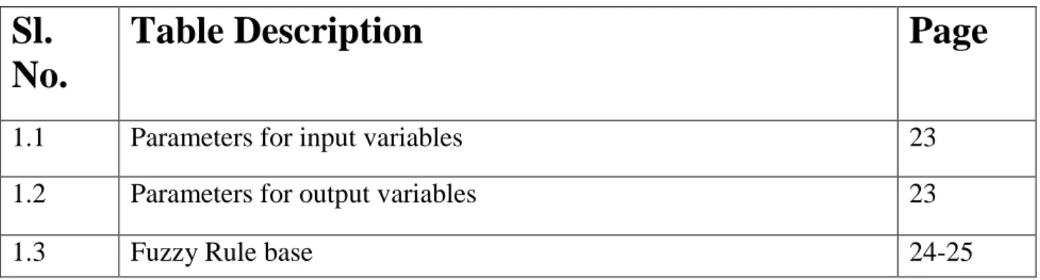
List of Tables
Sl.
No.
Table Description
Page
1.1 Parameters for input variables 23
1.2 Parameters for output variables 23
1.3 Fuzzy Rule base 24-25
8
Abstract
A fully autonomous robot is a programmable and multi-functional machine, possessing the ability to acquire information from its surroundings using different kinds of sensors to estimate and execute a collision free motion in its path towards a specified target. The unhindered navigation of mobile robots in an unstructured and dynamic environment is constrained by uncertainty, unreliability of input information, and unpredictability issues that plague the sensors and the robot controller. One of the long standing challenges in modern day mobile robotics is instilling the ability and intelligence in robots to autonomously navigate their path, avoiding structured and unstructured obstacles in real-time. An effective way of structuring the navigation path is designing the robot controller by implementing behavioral based approaches. In this project, research work has been carried out on the different fuzzy techniques which can be implemented for the navigation of a wheeled mobile robot, especially in a crowded and unpredictably dynamic environment and in the midst of static as well as dynamic obstacles. In this project, individual robot behaviors and their action coordination are addressed using fuzzy logic. It uses sets of linguistic fuzzy rules to implement expert knowledge in various situations. Later, it has been shown that the fuzzy model of the robot controller far outweighs the traditional algorithm based approach towards design of a robot control system. The proposed fuzzy scheme consists of inputs from an array of sensors located at the front, sides and rear of the mobile robot, which provide information about distances between obstacles to the front, left, right and back of the robot and the fuzzy rule base is run over these inputs to actuate the motion of the left and right wheels of the robot as per the situation encountered. Under the proposed fuzzy model, the mobile robot avoids all structured or unstructured obstacles in its path to reach the desired target. Robot path estimation and tracking is seen as one of the major challenging aspects of autonomous mobile robotics. Here, the robot prototype designed in laboratory effectively calculates and estimated its own path, avoiding all obstacles to reach its desired target. These experiments are conducted over a large variety of conditions and terrain to get a
9
satisfactory result on the success of the project. All the simulations are done in standard MATLAB environment and a hardware prototype of the robot is designed to check the matching degree of the simulated results with real world outputs, which unsurprisingly are in close agreement to one another.
10
Chapter 1
Introduction
Intelligent, robust and effective control of mobile robots is one of the challenging tasks of researchers and scientists across the globe. Mobile robots get so much attention in 21st century research due to their versatility and huge application potential for commercial usage in households, industry etc. Mobile robots can be used to perform critical surgeries, look for mines and oil deep beneath the sea bed, extensively used in space exploration, can be used instead of human workers on an industry‟s assembly line, drive cars, record valuable data in places impossible for humans to go etc. So, due to these wide ranges of applications, mobile robots have become one of the focal points of modern day research. Study of mobile robots combines researchers from diverse fields and backgrounds like electronics, mechanics, computer science, material sciences etc. A fully autonomous robot in the real world must possess abilities to:
a) Acquire information about the environment around it
b) Travel from source point to destination point without human navigation guidance or assistance
c) Avoid obstacles in its path to ensure a seamless passage throughout its motion ie-
have an effective control system in place which enables it to detect and avoid anything that is harmful for itself
d) Repair itself without assistance from outside in case of a breakdown or a system failure
11
The research is motivated by the gap between the current available technology and new Application demands. The current available industrial robots used in production and/or manufacturing lack flexibility, adaptability and autonomy, typically performing pre-programmed sequences of operations as pre-decided by the programmer, in highly constrained environments and these systems prove unable to function in new environments or face unexpected situations. Soft computing techniques like fuzzy logic, which use the tolerance for imprecision inherent in most real world systems, to improve performance of a system in an iterative manner have become hugely popular methods for controller design in mobile robotics. These techniques are used for expressing various subjective uncertainties in human-like behavior. The real world problems cannot be defined in crisp (hard) logic, and are characterized by uncertainties, so a fuzzy based modeling scheme was considered appropriate to design the controller of the robot in order to deal with real life data.
A robot also has to learn autonomously from its environment, after encountering various situations.
Autonomous learning includes the ability to [2]
(a) Learn or gain new capabilities without outside assistance (b) Adjust strategies based on the surroundings
(c) Adapt to surroundings without outside assistance.
In recent times, behavior based navigation systems have emerged as a fitting alternative to traditional strategy of reconstructing the environment and defining robotic actions based upon various predictable situations. This kind of a controller model, fails when the robot encounters situations that don‟t exist in its pre-programmed module. The advantage of behavior based approach is that we only define the rules and the robot generates its own outputs depending on the inputs received, whereas in the traditional approach we used to define the outputs or the robotic actions based upon various inputs, as per our knowledge. But, suppose we plan to send our robot to an alien environment, for example if we are interested in designing a robotic vehicle to send it to Jupiter‟s moon Europa to
12
search for signs of alien life, where the spacecraft has to land on the icy surface of Europa, the robot has to move out of the debris, navigate on the completely alien surface of the remote moon, then find a suitable spot to deploy a submersible that has to drill through layers and layers of ancient ice sheets with heat treatment techniques, and look for liquid water beneath the ice. During this process of drilling, the submersible bot has to navigate such that it avoids irregular obstacles in its path and safely makes its way down to the bottom, and if the bot finds liquid water at some depths, then it has to deploy a hydrobot (an aquatic robot) which then has the task of exploring the dark waters of the ancient ocean for even minute signs of life. If any favorable signs are found, then the information has to be relayed back to a base station on Earth. So, such kinds of expensive and highly classified missions require state of the art mobile robots that can safely find their own way out of trouble, return back to the base, repair themselves in case of emergency, store valuable information, require low power supplies etc. All these requirements and the example given above point more and more towards a behavioral model of robot control planning in the days to come.
In robot navigation, these three questions decide the robotic action
a) What is the current location of the robot with respect to the source position?
b) How is the local environment around the robot, what are the positions of the nearby obstacles?
c) Where is the destination point with respect to the robot‟s current location and in which direction should the robot head from its current location to reach its target?
The entire path to be followed is unknown to the robot, it just arrives at each junction point, where it is faced with some obstacles, from there it activates certain rules from its rule base to calculate the path of motion from that junction. So, slowly, the robot navigates its way through each junction by avoiding obstacles and ultimately reaches at its destination.
13
In the proposed fuzzy scheme in this project, there are 4 inputs to the robot‟s fuzzy controller. These are
The front obstacle distance(FOD)
Left obstacle distance(LOD)
Right obstacle distance(ROD)
Back obstacle distance(BOD)
These inputs are applied to the fuzzy controller to activate necessary rules from the rule base of the fuzzy controller and initiate robotic action which is given by the output parameters:
Left wheel velocity(LWV)
Right wheel velocity(RWV)
14
Fig 1.2 Fuzzy Controllers for Mobile Robot
Each input and output parameter of the fuzzy based controller is fuzzified into three membership functions. The inputs( FOD, LOD, ROD and BOD) are fuzzy sets defined with membership functions – NEAR, MEDIUM and FAR to map the input distance into a fuzzy quantity with membership grades or membership value [0,1] from these three membership functions. A similar operation is carried out with the wheel velocities with the membership functions being- SLOW, MED and FAST to fuzzify the output wheel velocities of the mobile robot.
15 Fig 1.3
16
Fig 1.4
Fuzzy based control systems are knowledge-based or rule-based systems made up of a collection of fuzzy IF-THEN rules based on the domain knowledge of human experts .The straightforwardness of fuzzy rule-based systems, their capacity to perform a wide range of tasks without hardcore computations and measurement operations make it immensely popular among researchers and scientists. Fuzzy logic control is a popular approach for controlling mobile robots because it is has the ability to make inferences even under high levels of uncertainty. And the final output‟s correctness depends less on the quality of the hardware used for constructing the robot, like it is less dependent on the quality of the sensors.
17
Chapter 2
Fundamentals of Fuzzy
Logic and its
application in Robot
Navigation
18
In this section, we have discussed various fundamental concepts of fuzzy logic and the following section discusses the implementation of these fuzzy concepts in the field of mobile robot navigation.
There are many fuzzy logic methods using various implementations or in combination with other techniques [4-8]. [9]Fuzzy Logic is a multivalued form of logic that allows intermediate values to be defined between conventional evaluations like 1 and 0, true/false, yes/no, high/low, etc. Statements like rather tall or very fast can be formulated mathematically and processed by computers, in order to apply a more human-like way of thinking in the programming of computers. This is vital because the real world systems and situations are hardly possible to model by using a hard logic based approach. [10]The concept of fuzzy logic is inspired by the remarkable human ability to reason with perception-based input information. The Rule based fuzzy logic provides a formal collection for linguistic rules resulting from reasoning and decision making with uncertain, unreliable and imprecise information. In fuzzy behavioral based navigation the problem is decomposed into smaller and simpler tasks (independent behaviors) and each behavior consists of a set of fuzzy logic rule statements which aim at achieving a well- defined set of objectives.
Fuzzy sets and terminologies
[4] Consider U to be a collection of objects denoted generically by {u}, which can be either discrete or continuous, where U is known as the universe of discourse and u signifies the generic element of U. A fuzzy set A is a universe of discourse U, characterized by a membership function µA which can take values from [0,1] and the corresponding value is called the membership grade of the function. A fuzzy set can be viewed as the generalization of a crisp set whose membership function can take only two values {0,1}. Therefore, a fuzzy set A in the universe U can be described as a set of ordered pairs of a generic element u and its grade of membership function:
19
When U is used for describing a continuous quantity, a fuzzy set A can be written as
A=
integrated over the entire universe of discourse U.
In case of a discrete quantity, the fuzzy set A can be represented as:
A=
µ
A(u
i)/u
i , summed over (i=1 to n)The support of a fuzzy set A is defined as the crisp set of all points u in the universe of discourse U such that
µ
A(u) 0.
The element u at whichµ
A=0.5 is known as the crossover point and a fuzzy set which has a support of a single point in U withµ
A=1.00 is known as a fuzzy singleton.[4]Operations on Fuzzy Sets
Let A and B be two fuzzy sets in the universe U with corresponding membership functions
µ
A andµ
B .Union of two fuzzy sets
The membership function of the union is point-wise defined for all u by the notation:
The membership function
Intersection of two fuzzy sets
The membership function of the union is point-wise defined for all u by the notation:
The membership function
Complement of two fuzzy sets
The membership function of the complement is point-wise defined for all u by the notation:
20
Processes in Fuzzy Logic Control
a) The following functions are performed by the fuzzification interface:
Measurement of the values of the input variables
A scale mapping is performed that transfers the range of values of input variables into corresponding universes of discourse
The process of fuzzification is performed that converts input data into suitable linguistic values which are viewed as the labels of the fuzzy sets b) The knowledge base contains information about the application domain and the
goals of the controller. It comprises of a database and a linguistic(fuzzy) control rule base
The database provides the required definitions, which are useful for defining linguistic control and data manipulation in the fuzzy domain.
The rule base is characterized by the control goals and control policies of the domain experts by means of a collection of linguistic control rules
c) The decision making logic is the brain of a fuzzy logic controller , enabled with the abilities to simulate human-like decision making based upon fuzzy concepts and of inferring fuzzy control actions by implementing fuzzy implication and the rules of inference in fuzzy logic
d) The defuzzification interface is indulded in performing the following operations:
It performs a scale mapping, that converts the range of values of the output variables into corresponding universes of discourse
Defuzzification yields a crisp control action from an inferred fuzzy control action
21
Application in the field of Mobile Robotics
[1]The fuzzy rule base consists of a set of linguistic rules of the form „if a set of conditions are satisfied, then a set of consequences are inferred‟.
For the four inputs and two outputs fuzzy system used in our project, the general fuzzy rule base consists of something like this:
Let the four inputs to the system be x1, x2, x3 and x4 and the two resultant outputs being y1 and y2.
If the(matching degree of x1 is μ(x1) and the matching degree of x2 is μ(x2) and the matching degree of x3 is μ(x3) and the matching degree of x4 is μ(x4)),
Then the(matching degree of vl is μ(yi)l and matching degree of vr is μ(yi)r).
Where vl and vr represent the left and right wheel velocities of the robot respectively Matching degree denoted by:
μ(yi)l,r = min{μ(x1), μ(x2),μ(x3), and μ(x4)}
where i = (1, 2, 3, . . . , n); x1, x2, x3, x4 = are the sensor inputs of left, right, front and back obstacle distances respectively;
μ(x1), μ(x2), μ(x3), μ(x4) represent the matching degrees of corresponding sensor inputs; vl, vr = the velocities of the left and right wheels respectively
μ(yi)l, μ(yi)r represent the inferred input matching degrees of corresponding left and right wheel velocities respectively.
Condition
When the matching degree=1, the inferred conclusion becomes identical to the rule‟s consequent, and if it is zero, then no conclusion can be drawn from the rule.
Finally, the output firing area of the left and right wheel velocities can be computed by the following formula
22
The final output (crisp value) of the fuzzy logic controller of left and right wheel velocities can be calculated by
Left and right wheel velocities
= ( )*( )
Where, μA(yi)l,r is the firing area of the left and right wheel velocities for the ith rule Vi the centroid distance of the area
n the total number of parameters
In our work, the sensor inputs are fuzzified by a combination of trapezoidal and triangular membership functions with the functions named as NEAR, MEDIUM and FAR
The output wheel velocities are fuzzified in a similar fashion and the membership functions are named as SLOW, MED and FAST
Parameters for variables
InputParameter(mtr)
NEAR MEDIUM FAR
Left_obs 0.0-0.6 0.6-0.9 0.9-1.2 Right_obs 0.0-0.6 0.6-0.9 0.9-1.2 Front_obs 0.0-0.6 0.6-0.9 0.9-1.2 Back_obs 0.0-0.6 0.6-0.9 0.9-1.2 Table-1.1 Output parameter(m/sec)
SLOW MED FAST
LW_vel 0-2 1-2 2-4
RW_vel 0-2 1-2 2-4
23
[2]Next, the fuzzy rule base is decided which is tabled below:
Rule No. Left_obs Right_obs Front_obs LW_vel RW_vel
1 Near Near Near Slow Fast
2 Near Near Medium Slow Slow
3 Near Near Far Med Med
4 Near Medium Near Med Slow
5 Near Medium Medium Med Slow
6 Near Medium Far Fast Med
7 Near Far Near Fast Slow
8 Near Far Medium Med Slow
9 Near Far Far Fast Med
10 Medium Medium Near Fast Slow
11 Medium Medium Medium Slow Slow
12 Medium Medium Far Fast Fast
13 Medium Near Near Slow Fast
14 Medium Near Medium Slow Med
15 Medium Near Far Slow Med
16 Medium Far Near Med Slow
17 Medium Far Medium Med Fast
18 Medium Far Far Fast Med
19 Far Near Near Slow Med
20 Far Near Medium Med Fast
21 Far Near Far Med Fast
22 Far Medium Near Slow Fast
23 Far Medium Medium Slow Med
24
25 Far Far Near Fast Slow
26 Far Far Medium Fast Med
27 Far Far Far Fast Fast
28 Far Far Near Med Slow
29 Far Medium Near Slow Med
30 Medium Far Near Fast Med
31 Near Far Medium Fast Med
32 Near Far Near Fast Med
33 Near Medium Far Med Slow
Table-1.3
The fuzzification of the inputs and outputs is done through the fuzzy interface toolbox of Simulink
25
Fig-2.2
26 Fig 2.4
27 Fig-2.6
28
Chapter 3
Hardware
Implementation of the
Robot Design
29
Robot’s Hardware Prototype
30
Construction of the Mobile Robot
Materials Required:
Atmega 32 Development Board
Atmega 32 Microcontroller
Wheels for placing at rear side
Castor Wheel acting as front wheels
TSOP Infrared sensor modules
L293D Motor Driver
Body/Chassis of the Robot
Li-ion 9V battery
AVR USB Programmer
Soldering Materials
Ribbon wires
DC Motors(high torque) – 200rpm
Battery Charger
Power supply jacks, pin connectors
USB to USB Connector Cable
Laptop for programming
AVR Studio 4 Programming environment
31
Major Hardware Components used
:
1)
ATMEGA 32 Development Board
Fig-3.2
(6)In this project, we used the ATMEGA 32 Development Board made by NexRobotics. It is made from double sided PTH PCB board to provide extra strength to the connector joints for increased reliability. The Board is compatible for voltages ranging from 7 to 15V AC or DC supply. It has built-in reverse polarity protection feature. The board contains a 7805 voltage regulator which has been fitted with a suitable heat sink for heat dissipation so that it can supply 1Amp current continuously without getting over heated. It has switches for boot loading, reset and power. It also has a RS232 interface with DB9 female connector based on MAX232. All the ports are connected to standard 10 pin FRC connectors. Open pads for connecting microcontroller‟s pins to external devices are also provided.
32
Specifications
Microcontroller: ATMEGA32 with 14.7456MHz crystal (Also supports ATMEGA16)
Double side high quality PTH PCB for added strength.
Power: 7 to 15V, AC or DC, Heat sink on 7805 for better current rating
Reverse polarity protected
Switches: Boot, Reset, Power
RS232 serial interface
10 pin FRC connectors and soldering pads on all ports
Compatible with General purpose prototyping board for development board for stackable design
Application examples in AVR studio provided in the documentation CD
2)
ATMEGA 32 Microcontroller
33
(6)
Special Features
Advanced RISC Architecture
Up to 16 MIPS Throughput at 14.7456 MHz
32K Bytes of In-System Self-Programmable Flash
1024 Bytes EEPROM
2K Byte Internal SRAM
32 Programmable I/O Lines
In-System Programming by On-chip Boot Program
8-channel, 10-bit ADC
8 Single-ended Channels
2 Differential Channels with Programmable Gain at 1x, 10x, or 200x
Two 8-bit Timer/Counters with Separate Prescalers and Compare Modes
One 16-bit Timer/Counter with Separate Prescaler, Compare Mode, and Capture
Real Time Counter with Separate Oscillator
Four PWM Channels
Programmable Serial USART
Master/Slave SPI Serial Interface
Byte-oriented Two-wire Serial Interface
Programmable Watchdog Timer with Separate On-chip Oscillator
External and Internal Interrupt Sources
34
3)
Single TSOP Sensor Modules
Fig-3.4
TSOP sensor modules were implemented in this project to obtain the obstacle distances. The module consists of a IR transmitter and a TSOP receiver. These sensors transmit and detect infrared light of 38 kHz. On detection of an obstacle, the sensor module outputs a 0.
Construction Methodology
First, the chassis of the mobile robot is fabricated and laid out. Then, the rear wheels are fitted in the grooves and the castor wheel is fitted at the front as an alternative to fitting two more front wheels. Then, the DC motors are fitted to the rear axles. These motors are specially designed motors that provide high torque to the wheels. We have used specially made Li-ion batteries (9V) which can provide high current for the device to function as per requirement. TSOP Sensor modules are then fitted at the front, left, right and back of the robot. Then drilling and cutting operations are carried out to fix various components into the chassis.
35
The development board is finally placed on the top and other wiring operations are carried out, connections are made and the power source is fitted below the body. Next, power is turned ON through the push-button and sensors are checked for correct working by waving one‟s hand in front of them. The detection of an obstacle by the sensor is confirmed by the glow of a LED. Then, the sensors are calibrated by setting the range of detection of all sensors equal. This can be done by tuning the potentiometer knob present on the TSOP sensor. This is important to ensure that all sensors detect the presence of an obstacle from the same distance, which is of utmost importance while taking turns and especially sharp turns. The motor driver module should also be checked by giving power supply and checking the voltage at its output pins by a multi-meter. It should also be checked and ensured that the wheels are moving parallel to the bot chassis .The TSOP sensors are suitably calibrated to provide analog voltages proportional to the distance between sensor and obstacle (if any).The alignment of the IR sensor LEDs should be made pointing outwards from their location on the robot‟ body and all the sensors should be checked properly for this. This will ensure seamless acquisition of input obstacle distances from the environment by both sensors present on each of the three sides of the robot.
Working of the Robot:
The infrared sensors present at the front, sides and back of the robot constantly monitor the nearby environment for obstacles on all sides of the robot, the obstacles are assumed to be real-life obstacles, ie- not belonging to any particular shape or known structure.
The TSOP sensors, after suitable calibration, provide analog voltage output proportional to the distance between a sensor and an obstacle. The detection distance must be set to be same for all the 7 sensors.
This analog voltage value is fed to the ADC of the Atmega 32, which samples it and converts it into digital form, to be used for further processing.
36
The fuzzy rule base, has been burnt in the microcontroller, after coding in the AVR Studio4 Environment.
The NEAR, MEDIUM and FAR distances for obstacles are considered as 3 digital threshold values in the digital domain for programming purposes. Similarly, it is carried out for SLOW, MEDIUM and FAST for the wheel velocities.
After, the processing is done by the microcontroller for the given code‟s logic, the required output pins are activated(PORT B), which are connected to the motor driver circuit.
The motor driver circuit makes the wheels of the robot go forward or backward based upon the polarities of voltages at its 4 outputs.
37
Chapter 4
Software Aspects
-Programming
38
The entire programming of the microcontroller‟s flash was done in AVR Studio 4 software environment. The software supports AVR C language, and the code written in its editor can be converted into .hex file format which is suitable for being dumped into ATMEGA microcontroller after compilation.
39
AVR C code:
#define Front_sensor1 PINA&0b00000001 #define Front_sensor2 PINA&0b00000010 #define Left_sensor1 PINA&0b00000100 #define Left_sensor2 PINA&0b00001000 #define Right_sensor1 PINA&0b00010000 #define Right_sensor2 PINA&0b00100000 #define Back_sensor PINA&0b01000000
#include<avr/io.h> #include<util/delay.h> int main(void) { DDRA=0X00; DDRB=0XFF; while(1) { if((Front_sensor1==0x00)&&(Front_sensor2==0x00)) {
40 PORTB=0x08; _delay_s(2); } if((Front_sensor1==0x01)&&(Front_sensor2==0x00)) { PORTB=0b00000101; _delay_s(1); } if((Front_sensor1==0x00)&&(Front_sensor2==0x01)) { PORTB=0b00001010; _delay_s(1); } if((Left_sensor1==0x00)&&(Left_sensor2==0x00)) { PORTB=0b00001000; _delay_s(2); } if((Left_sensor1==0x01)&&(Left_sensor2==0x00)) {
41 PORTB=0b00001010; _delay_s(2); } if((Left_sensor1==0x00)&&(Left_sensor2==0x01)) { PORTB=0b00001000; _delay_s(1); } if((Right_sensor1==0x00)&&(Right_sensor2==0x00)) { PORTB=0b00000001; _delay_s(2); } if((Right_sensor1==0x01)&&(Right_sensor2==0x00)) { PORTB=0b00000101; _delay_s(2); } if((Right_sensor1==0x00)&&(Right_sensor1==0x01)) {
42 PORTB=0b00000001; _delay_s(1); } if(Back_sensor==0x00) { PORTB=0X09; _delay_s(1); } else PORTB=0X09; } }
43
Robot Simulator Design in MATLAB
To view and understand the general path planning procedure followed by a mobile robot when its task is to steer clear of obstacles and reach a specified target, this Robot Simulator was designed by us:
MATLAB Code clc; clear all; close all; whitebg('k') x=0; y=0;
tarx=input('enter the target in x axis = ') tary=input('enter the target in y axis = ')
rectangle('position',[tarx,tary,6,6],'curvature',[0,1],'facecolor','w','edgecolor','b','linewidth', 3)
figure(1) hold on
obsx1=input('enter the obstacle1 in x axis = ') obsy1=input('enter the obstacle1 in y axis = ')
rectangle('position',[obsx1,obsy1,15,20],'curvature',[0,1],'facecolor','r','edgecolor','b','line width',2)
figure(1) hold on
obsx2=input('enter the obstacle2 in x axis = ') obsy2=input('enter the obstacle2 in y axis = ')
rectangle('position',[obsx2,obsy2,18,18],'curvature',[1,1],'facecolor','g','edgecolor','b','line width',2)
44 figure(1)
hold on
obsx3=input('enter the obstacle3 in x axis = ') obsy3=input('enter the obstacle3 in y axis = ')
rectangle('position',[obsx3,obsy3,16,17],'curvature',[0,1],'facecolor','b','edgecolor','w','line width',2)
figure(1) hold on
theta=input('enter the head angle = ') hold on %theta=atand((tary-y)./(tarx-x)) %rectangle('position',[obsx1,obsy1,10,10],'curvature',[0,1],'facecolor','r','edgecolor','b','lin ewidth',2) %hold on %rectangle('position',[obsx2,obsy2,10,10],'curvature',[1,1],'facecolor','g','edgecolor','b','lin ewidth',5) %hold on %rectangle('position',[obsx3,obsy3,15,15],'curvature',[0,1],'facecolor','b','edgecolor','w','li newidth',5) %hold on %rectangle('position',[tarx,tary,4,4],'curvature',[1,1],'facecolor','c','edgecolor','m','linewidt h',2) %hold on figure(1) for i=0:1:10000 x=x+cosd(theta) y=y+sind(theta)
rectangle('position',[x,y,5,5],'curvature',[0,1],'facecolor','r','edgecolor','g','linewidth',2) tardist=sqrt((tarx-x).^2+(tary-y).^2)
45 obsdist1=sqrt((obsx1-x).^2+(obsy1-y).^2) obsdist2=sqrt((obsx2-x).^2+(obsy2-y).^2) obsdist3=sqrt((obsx3-x).^2+(obsy3-y).^2) pause(0.1)
%%if (obsdist1<=10) || (obsdist2<=10) || (obsdist3<=10) %%theta=theta+15
%%elseif
if (obsdist1<=18) || (obsdist2<=20) || (obsdist3<=22) theta=theta-15 else theta=atand((tary-y)./(tarx-x)) end %if (obsdist2<=15) % theta=theta+18 %else theta=atand((tary-y)./(tarx-x)) %end if (tardist<=3.7) break end end OUTPUT
enter the target in x axis = 150
tarx = 150
enter the target in y axis = 150
46 enter the obstacle1 in x axis = 30
obsx1 =30
enter the obstacle1 in y axis = 39
obsy1 =39
enter the obstacle2 in x axis = 65
obsx2 =65
enter the obstacle2 in y axis = 67
obsy2 = 67
enter the obstacle3 in x axis = 110
obsx3 =110
enter the obstacle3 in y axis = 110
obsy3 = 110
47
The Robot Simulator environment looked something like this:
Fig-4.2
48 Fig-4.4 Fig-4.5
49
Chapter 5
Application
as
an
Obstacle Detector
The robotic prototype is implemented as an obstacle detector in order to showcase its autonomous behavior. It is made to encounter a maze of 3 obstacles in a laboratory environment to test the effectiveness of the programming and the matching degree of simulations and real world trials.
50
Fig 5.1
51 Fig-5.3 Fig-5.4
52
53
Chapter 6
Conclusion and Future Work
The work done in the project highlights the importance of behavioral based models of mobile robot navigation as important pathways for the future of autonomous mobile robotics. The work implemented in this project of making an obstacle avoidance robot would not have been possible with traditional methods. Thus, in the days to come, we will see more and more applications of fuzzy and neural models of robot controllers which are less dependent on sensor quality, can deal with noisy data, are open to newer features addition, are robust in nature and more importantly have been found to take the correct decision in maximum cases when put to test as compared to traditional, highly constrained robots. This work is extending to multiple mobile robots instead of single mobile robot.
54
References
1. O. OBE, and I. DUMITRACHE, “Fuzzy control of autonomous mobile Robot,” U.P.B. Sci. Bull., Series C, Vol. 72, Issue. 3, 2010
2. D.R. Parhi and M.K. Singh, Intelligent fuzzy interface technique for controller of mobile robot. J. of Mech. Engineering part C, vol. 222 no.11, pp. 2281-2292, 2008
3. D. R. Parhi "Navigation of mobile robot using a fuzzy logic controller", J. Intell. Robot. Syst., vol. 42, no. 35, pp.253 -273 2005
4. Huq, R., Mann, G.K.I., Gosine, R.G.: Mobile robot navigation using motor schema and fuzzy content behavior modulation. Application of soft computing. 8, 422-436 (2008)
5. Selekwa, M.F., Dunlap, D.D., Shi, D., CollinsJr, E.G.: Robot navigation in very cluttered environment by preference based fuzzy behaviors. Autonomous system. 56, 231-246 (2007)
6. Abdessemed, F., Benmahammed, K., Monacelli, E.: A fuzzy based reactive controller for a non-holonomic mobile robot. Robotics Autonomous system. 47, 31-46 (2004)
7. Pradhan, S.K., Parhi, D.R., Panda, A.K.: Fuzzy logic techniques for navigation of several mobile robots. Application of soft computing. 9, 290-304 (2009)
8. Motlagh, O., Tang, S.H., Ismail, N.: Development of a new minimum avoidance system for behavior based mobile robot, Fuzzy Sets System 160, 1929-1946 (2009)
9. A. Fatmi, A. A. Yahmadi, L. Khriji, and N. Masmoudi, "A fuzzy logic based
navigation of a mobile robot," in 22nd World Academy of Science, Engineering and Technology, 2006, pp. 169-174.
10.Hellmann, M.: Fuzzy logic introduction. Université de Rennes (2001)
11.www.nex-robotics.com 12.www.mathworks.com