The Design and Implementation of a Log-Structured File System
Mendel Rosenblum and John K. OusterhoutElectrical Engineering and Computer Sciences, Computer Science Division University of California
Berkeley, CA 94720
[email protected], [email protected]
Abstract
This paper presents a new technique for disk storage management called a log-structured file system. A log-structured file system writes all modifications to disk sequentially in a log-like structure, thereby speeding up bothfile writing and crash recovery. The log is the only structure on disk; it contains indexing information so that
files can be read back from the log efficiently. In order to maintain large free areas on disk for fast writing, we divide the log into segments and use a segment cleaner to compress the live information from heavily fragmented segments. We present a series of simulations that demon-strate the efficiency of a simple cleaning policy based on cost and benefit. We have implemented a prototype log-structured file system called Sprite LFS; it outperforms current Unix file systems by an order of magnitude for small-file writes while matching or exceeding Unix perfor-mance for reads and large writes. Even when the overhead for cleaning is included, Sprite LFS can use 70% of the disk bandwidth for writing, whereas Unixfile systems typi-cally can use only 5-10%.
1. Introduction
Over the last decade CPU speeds have increased dramatically while disk access times have only improved slowly. This trend is likely to continue in the future and it will cause more and more applications to become disk-bound. To lessen the impact of this problem, we have dev-ised a new disk storage management technique called a
log-structured file system, which uses disks an order of
The work described here was supported in part by the Na-tional Science Foundation under grant CCR-8900029, and in part by the National Aeronautics and Space Administration and the Defense Advanced Research Projects Agency under contract NAG2-591.
This paper will appear in theProceedings of the 13th ACM Sym-posium on Operating Systems Principlesand the February 1992 ACM Transactions on Computer Systems.
magnitude more efficiently than currentfile systems. Log-structuredfile systems are based on the assump-tion thatfiles are cached in main memory and that increas-ing memory sizes will make the caches more and more effective at satisfying read requests[1]. As a result, disk traffic will become dominated by writes. A log-structured
file system writes all new information to disk in a sequen-tial structure called thelog. This approach increases write performance dramatically by eliminating almost all seeks. The sequential nature of the log also permits much faster crash recovery: current Unix file systems typically must scan the entire disk to restore consistency after a crash, but a log-structured file system need only examine the most recent portion of the log.
The notion of logging is not new, and a number of recent file systems have incorporated a log as an auxiliary structure to speed up writes and crash recovery[2, 3]. How-ever, these other systems use the log only for temporary storage; the permanent home for information is in a tradi-tional random-access storage structure on disk. In contrast, a log-structured file system stores data permanently in the log: there is no other structure on disk. The log contains indexing information so that files can be read back with efficiency comparable to currentfile systems.
For a log-structuredfile system to operate efficiently, it must ensure that there are always large extents of free space available for writing new data. This is the most difficult challenge in the design of a log-structuredfile sys-tem. In this paper we present a solution based on large extents called segments, where a segment cleanerprocess continually regenerates empty segments by compressing the live data from heavily fragmented segments. We used a simulator to explore different cleaning policies and discovered a simple but effective algorithm based on cost and benefit: it segregates older, more slowly changing data from young rapidly-changing data and treats them dif-ferently during cleaning.
We have constructed a prototype log-structured file system called Sprite LFS, which is now in production use as part of the Sprite network operating system[4]. Bench-mark programs demonstrate that the raw writing speed of Sprite LFS is more than an order of magnitude greater than that of Unix for smallfiles. Even for other workloads, such
as those including reads and large-file accesses, Sprite LFS is at least as fast as Unix in all cases but one (files read sequentially after being written randomly). We also meas-ured the long-term overhead for cleaning in the production system. Overall, Sprite LFS permits about 65-75% of a disk’s raw bandwidth to be used for writing new data (the rest is used for cleaning). For comparison, Unix systems can only utilize 5-10% of a disk’s raw bandwidth for writ-ing new data; the rest of the time is spent seekwrit-ing.
The remainder of this paper is organized into six sec-tions. Section 2 reviews the issues in designingfile sys-tems for computers of the 1990’s. Section 3 discusses the design alternatives for a log-structured file system and derives the structure of Sprite LFS, with particular focus on the cleaning mechanism. Section 4 describes the crash recovery system for Sprite LFS. Section 5 evaluates Sprite LFS using benchmark programs and long-term measure-ments of cleaning overhead. Section 6 compares Sprite LFS to otherfile systems, and Section 7 concludes.
2. Design for
fi
le systems of the 1990’s
File system design is governed by two general forces: technology, which provides a set of basic building blocks, and workload, which determines a set of operations that must be carried out efficiently. This section summar-izes technology changes that are underway and describes their impact on file system design. It also describes the workloads that influenced the design of Sprite LFS and shows how current file systems are ill-equipped to deal with the workloads and technology changes.2.1. Technology
Three components of technology are particularly significant for file system design: processors, disks, and main memory. Processors are significant because their speed is increasing at a nearly exponential rate, and the improvements seem likely to continue through much of the 1990’s. This puts pressure on all the other elements of the computer system to speed up as well, so that the system doesn’t become unbalanced.
Disk technology is also improving rapidly, but the improvements have been primarily in the areas of cost and capacity rather than performance. There are two com-ponents of disk performance: transfer bandwidth and access time. Although both of these factors are improving, the rate of improvement is much slower than for CPU speed. Disk transfer bandwidth can be improved substan-tially with the use of disk arrays and parallel-head disks[5] but no major improvements seem likely for access time (it is determined by mechanical motions that are hard to improve). If an application causes a sequence of small disk transfers separated by seeks, then the application is not likely to experience much speedup over the next ten years, even with faster processors.
The third component of technology is main memory, which is increasing in size at an exponential rate. Modern
file systems cache recently-usedfile data in main memory,
and larger main memories make largerfile caches possible. This has two effects onfile system behavior. First, larger
file caches alter the workload presented to the disk by absorbing a greater fraction of the read requests[1, 6]. Most write requests must eventually be reflected on disk for safety, so disk traffic (and disk performance) will become more and more dominated by writes.
The second impact of large file caches is that they can serve as write buffers where large numbers of modified blocks can be collected before writing any of them to disk. Buffering may make it possible to write the blocks more efficiently, for example by writing them all in a single sequential transfer with only one seek. Of course, write-buffering has the disadvantage of increasing the amount of data lost during a crash. For this paper we will assume that crashes are infrequent and that it is acceptable to lose a few seconds or minutes of work in each crash; for applications that require better crash recovery, non-volatile RAM may be used for the write buffer.
2.2. Workloads
Several differentfile system workloads are common in computer applications. One of the most difficult work-loads for file system designs to handle efficiently is found in office and engineering environments. Office and engineering applications tend to be dominated by accesses to small files; several studies have measured mean file sizes of only a few kilobytes[1, 6-8]. Small files usually result in small random disk I/Os, and the creation and dele-tion times for such files are often dominated by updates to
file system ‘‘metadata’’ (the data structures used to locate the attributes and blocks of thefile).
Workloads dominated by sequential accesses to large
files, such as those found in supercomputing environments, also pose interesting problems, but not for file system software. A number of techniques exist for ensuring that such files are laid out sequentially on disk, so I/O perfor-mance tends to be limited by the bandwidth of the I/O and memory subsystems rather than thefile allocation policies. In designing a log-structured file system we decided to focus on the efficiency of small-file accesses, and leave it to hardware designers to improve bandwidth for large-file accesses. Fortunately, the techniques used in Sprite LFS work well for largefiles as well as small ones.
2.3. Problems with existing
fi
le systems
Current file systems suffer from two general prob-lems that make it hard for them to cope with the technolo-gies and workloads of the 1990’s. First, they spread infor-mation around the disk in a way that causes too many small accesses. For example, the Berkeley Unix fast file system (Unix FFS)[9] is quite effective at laying out each file sequentially on disk, but it physically separates differentfiles. Furthermore, the attributes (‘‘inode’’) for a file are separate from the file’s contents, as is the directory entry containing the file’s name. It takes at least five separate disk I/Os, each preceded by a seek, to create a new file in
Unix FFS: two different accesses to the file’s attributes plus one access each for thefile’s data, the directory’s data, and the directory’s attributes. When writing smallfiles in such a system, less than 5% of the disk’s potential bandwidth is used for new data; the rest of the time is spent seeking.
The second problem with currentfile systems is that they tend to write synchronously: the application must wait for the write to complete, rather than continuing while the write is handled in the background. For example even though Unix FFS writes file data blocks asynchronously,
file system metadata structures such as directories and inodes are written synchronously. For workloads with many smallfiles, the disk traffic is dominated by the syn-chronous metadata writes. Synsyn-chronous writes couple the application’s performance to that of the disk and make it hard for the application to benefit from faster CPUs. They also defeat the potential use of the file cache as a write buffer. Unfortunately, network file systems like NFS[10] have introduced additional synchronous behavior where it didn’t used to exist. This has simplified crash recovery, but it has reduced write performance.
Throughout this paper we use the Berkeley Unix fast
file system (Unix FFS) as an example of currentfile system design and compare it to log-structured file systems. The Unix FFS design is used because it is well documented in the literature and used in several popular Unix operating systems. The problems presented in this section are not unique to Unix FFS and can be found in most otherfile sys-tems.
3. Log-structured
fi
le systems
The fundamental idea of a log-structuredfile system is to improve write performance by buffering a sequence of
file system changes in thefile cache and then writing all the changes to disk sequentially in a single disk write opera-tion. The information written to disk in the write operation includes file data blocks, attributes, index blocks,
Data structure Purpose Location Section
Inode Locates blocks offile, holds protection bits, modify time, etc. Log 3.1
Inode map Locates position of inode in log, holds time of last access plus version number. Log 3.1
Indirect block Locates blocks of largefiles. Log 3.1
Segment summary Identifies contents of segment (file number and offset for each block). Log 3.2
Segment usage table Counts live bytes still left in segments, stores last write time for data in segments. Log 3.6
Superblock Holds static configuration information such as number of segments and segment size. Fixed None
Checkpoint region Locates blocks of inode map and segment usage table, identifies last checkpoint in log. Fixed 4.1
Directory change log Records directory operations to maintain consistency of reference counts in inodes. Log 4.2
Table 1 — Summary of the major data structures stored on disk by Sprite LFS.
For each data structure the table indicates the purpose served by the data structure in Sprite LFS. The table also indicates whether the data structure is stored in the log or at afixed position on disk and where in the paper the data structure is discussed in detail. Inodes, indirect blocks, and superblocks are similar to the Unix FFS data structures with the same names. Note that Sprite LFS contains neither a bitmap nor a free list.
directories, and almost all the other information used to manage the file system. For workloads that contain many smallfiles, a log-structured file system converts the many small synchronous random writes of traditionalfile systems into large asynchronous sequential transfers that can utilize nearly 100% of the raw disk bandwidth.
Although the basic idea of a log-structured file sys-tem is simple, there are two key issues that must be resolved to achieve the potential benefits of the logging approach. The first issue is how to retrieve information from the log; this is the subject of Section 3.1 below. The second issue is how to manage the free space on disk so that large extents of free space are always available for writing new data. This is a much more difficult issue; it is the topic of Sections 3.2-3.6. Table 1 contains a summary of the on-disk data structures used by Sprite LFS to solve the above problems; the data structures are discussed in detail in later sections of the paper.
3.1. File location and reading
Although the term ‘‘log-structured’’ might suggest that sequential scans are required to retrieve information from the log, this is not the case in Sprite LFS. Our goal was to match or exceed the read performance of Unix FFS. To accomplish this goal, Sprite LFS outputs index struc-tures in the log to permit random-access retrievals. The basic structures used by Sprite LFS are identical to those used in Unix FFS: for eachfile there exists a data structure called an inode, which contains the file’s attributes (type, owner, permissions, etc.) plus the disk addresses of the
first ten blocks of thefile; forfiles larger than ten blocks, the inode also contains the disk addresses of one or more
indirect blocks, each of which contains the addresses of
more data or indirect blocks. Once afile’s inode has been found, the number of disk I/Os required to read the file is identical in Sprite LFS and Unix FFS.
In Unix FFS each inode is at afixed location on disk; given the identifying number for afile, a simple calculation
yields the disk address of the file’s inode. In contrast, Sprite LFS doesn’t place inodes atfixed positions; they are written to the log. Sprite LFS uses a data structure called
an inode map to maintain the current location of each
inode. Given the identifying number for afile, the inode map must be indexed to determine the disk address of the inode. The inode map is divided into blocks that are writ-ten to the log; a fixed checkpoint region on each disk identifies the locations of all the inode map blocks. For-tunately, inode maps are compact enough to keep the active portions cached in main memory: inode map lookups rarely require disk accesses.
Figure 1 shows the disk layouts that would occur in Sprite LFS and Unix FFS after creating two new files in different directories. Although the two layouts have the same logical structure, the log-structured file system pro-duces a much more compact arrangement. As a result, the write performance of Sprite LFS is much better than Unix FFS, while its read performance is just as good.
3.2. Free space management: segments
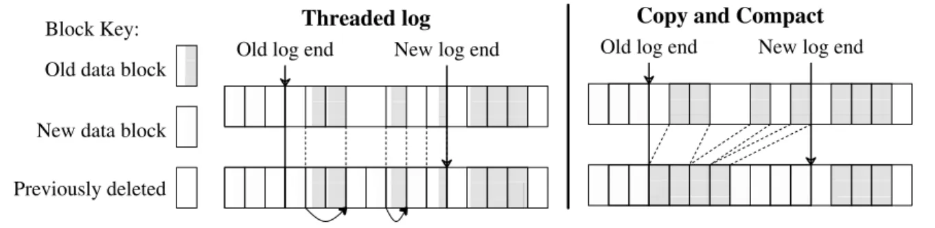
The most difficult design issue for log-structuredfile systems is the management of free space. The goal is to maintain large free extents for writing new data. Initially all the free space is in a single extent on disk, but by the time the log reaches the end of the disk the free space will have been fragmented into many small extents correspond-ing to thefiles that were deleted or overwritten.From this point on, thefile system has two choices: threading and copying. These are illustrated in Figure 2. The first alternative is to leave the live data in place and thread the log through the free extents. Unfortunately, threading will cause the free space to become severely fragmented, so that large contiguous writes won’t be possi-ble and a log-structuredfile system will be no faster than
file2
file1
dir2 dir1
Block key: Inode Directory Data
Disk file2 dir2 file1 dir1 Disk
Unix FFS
Sprite LFS
Inode map LogFigure 1 — A comparison between Sprite LFS and Unix FFS.
This example shows the modified disk blocks written by Sprite LFS and Unix FFS when creating two single-block files named dir1/file1and dir2/file2. Each system must write new data blocks and inodes for file1and file2, plus new data blocks and inodes for the containing directories. Unix FFS requires ten non-sequential writes for the new information (the inodes for the newfiles are each written twice to ease recovery from crashes), while Sprite LFS performs the operations in a single large write. The same number of disk accesses will be required to read thefiles in the two systems. Sprite LFS also writes out new inode map blocks to record the new inode locations.
traditional file systems. The second alternative is to copy live data out of the log in order to leave large free extents for writing. For this paper we will assume that the live data is written back in a compacted form at the head of the log; it could also be moved to another log-structuredfile system to form a hierarchy of logs, or it could be moved to some totally differentfile system or archive. The disadvantage of copying is its cost, particularly for long-lived files; in the simplest case where the log works circularly across the disk and live data is copied back into the log, all of the long-lived files will have to be copied in every pass of the log across the disk.
Sprite LFS uses a combination of threading and copying. The disk is divided into large fixed-size extents called segments. Any given segment is always written sequentially from its beginning to its end, and all live data must be copied out of a segment before the segment can be rewritten. However, the log is threaded on a segment-by-segment basis; if the system can collect long-lived data together into segments, those segments can be skipped over so that the data doesn’t have to be copied repeatedly. The segment size is chosen large enough that the transfer time to read or write a whole segment is much greater than the cost of a seek to the beginning of the segment. This allows whole-segment operations to run at nearly the full bandwidth of the disk, regardless of the order in which seg-ments are accessed. Sprite LFS currently uses segment sizes of either 512 kilobytes or one megabyte.
3.3. Segment cleaning mechanism
The process of copying live data out of a segment is called segment cleaning. In Sprite LFS it is a simple three-step process: read a number of segments into memory, identify the live data, and write the live data back to a smaller number of clean segments. After this
operation is complete, the segments that were read are marked as clean, and they can be used for new data or for additional cleaning.
As part of segment cleaning it must be possible to identify which blocks of each segment are live, so that they can be written out again. It must also be possible to iden-tify thefile to which each block belongs and the position of the block within thefile; this information is needed in order to update thefile’s inode to point to the new location of the block. Sprite LFS solves both of these problems by writing
a segment summary block as part of each segment. The
summary block identifies each piece of information that is written in the segment; for example, for eachfile data block the summary block contains the file number and block number for the block. Segments can contain multiple seg-ment summary blocks when more than one log write is needed to fill the segment. (Partial-segment writes occur when the number of dirty blocks buffered in thefile cache is insufficient tofill a segment.) Segment summary blocks impose little overhead during writing, and they are useful during crash recovery (see Section 4) as well as during cleaning.
Sprite LFS also uses the segment summary informa-tion to distinguish live blocks from those that have been overwritten or deleted. Once a block’s identity is known, its liveness can be determined by checking thefile’s inode or indirect block to see if the appropriate block pointer still refers to this block. If it does, then the block is live; if it doesn’t, then the block is dead. Sprite LFS optimizes this check slightly by keeping a version number in the inode map entry for eachfile; the version number is incremented whenever the file is deleted or truncated to length zero. The version number combined with the inode number form an unique identifier (uid) for the contents of thefile. The segment summary block records this uid for each block in
Old log end New log end Copy and Compact Block Key:
Previously deleted New data block Old data block
Threaded log New log end Old log end
Figure 2 — Possible free space management solutions for log-structuredfile systems.
In a log-structuredfile system, free space for the log can be generated either by copying the old blocks or by threading the log around the old blocks. The left side of thefigure shows the threaded log approach where the log skips over the active blocks and overwrites blocks of files that have been deleted or overwritten. Pointers between the blocks of the log are maintained so that the log can be followed during crash recovery. The right side of thefigure shows the copying scheme where log space is generated by reading the section of disk after the end of the log and rewriting the active blocks of that section along with the new data into the newly generated space.
the segment; if the uid of a block does not match the uid currently stored in the inode map when the segment is cleaned, the block can be discarded immediately without examining thefile’s inode.
This approach to cleaning means that there is no free-block list or bitmap in Sprite. In addition to saving memory and disk space, the elimination of these data struc-tures also simplifies crash recovery. If these data structures existed, additional code would be needed to log changes to the structures and restore consistency after crashes.
3.4. Segment cleaning policies
Given the basic mechanism described above, four policy issues must be addressed:
(1) When should the segment cleaner execute? Some possible choices are for it to run continuously in background at low priority, or only at night, or only when disk space is nearly exhausted.
(2) How many segments should it clean at a time? Seg-ment cleaning offers an opportunity to reorganize data on disk; the more segments cleaned at once, the more opportunities to rearrange.
(3) Which segments should be cleaned? An obvious choice is the ones that are most fragmented, but this turns out not to be the best choice.
(4) How should the live blocks be grouped when they are written out? One possibility is to try to enhance the locality of future reads, for example by grouping
files in the same directory together into a single out-put segment. Another possibility is to sort the blocks by the time they were last modified and group blocks of similar age together into new segments; we call this approachage sort.
In our work so far we have not methodically addressed thefirst two of the above policies. Sprite LFS starts cleaning segments when the number of clean seg-ments drops below a threshold value (typically a few tens of segments). It cleans a few tens of segments at a time until the number of clean segments surpasses another thres-hold value (typically 50-100 clean segments). The overall performance of Sprite LFS does not seem to be very sensi-tive to the exact choice of the threshold values. In contrast, the third and fourth policy decisions are critically impor-tant: in our experience they are the primary factors that determine the performance of a log-structuredfile system. The remainder of Section 3 discusses our analysis of which segments to clean and how to group the live data.
We use a term calledwrite costto compare cleaning policies. The write cost is the average amount of time the disk is busy per byte of new data written, including all the cleaning overheads. The write cost is expressed as a multi-ple of the time that would be required if there were no cleaning overhead and the data could be written at its full bandwidth with no seek time or rotational latency. A write cost of 1.0 is perfect: it would mean that new data could be written at the full disk bandwidth and there is no cleaning overhead. A write cost of 10 means that only one-tenth of the disk’s maximum bandwidth is actually used for writing new data; the rest of the disk time is spent in seeks, rota-tional latency, or cleaning.
For a log-structuredfile system with large segments, seeks and rotational latency are negligible both for writing and for cleaning, so the write cost is the total number of bytes moved to and from the disk divided by the number of those bytes that represent new data. This cost is deter-mined by the utilization (the fraction of data still live) in the segments that are cleaned. In the steady state, the cleaner must generate one clean segment for every segment of new data written. To do this, it reads N segments in their entirety and writes out N*u segments of live data (whereuis the utilization of the segments and 0≤u< 1). This creates N*(1−u) segments of contiguous free space for new data. Thus
write cost = total bytes read and writtennew data written = read segsnew data written+write live+write new
(1)
= N+N*N*(1u+−N*(1u) −u) = 1−2u
In the above formula we made the conservative assumption that a segment must be read in its entirety to recover the live blocks; in practice it may be faster to read just the live blocks, particularly if the utilization is very low (we haven’t tried this in Sprite LFS). If a segment to be cleaned has no live blocks (u= 0) then it need not be read at all and the write cost is 1.0.
Figure 3 graphs the write cost as a function ofu. For reference, Unix FFS on small-file workloads utilizes at most 5-10% of the disk bandwidth, for a write cost of 10-20 (see [11] and Figure 8 in Section 5.1 for specific measurements). With logging, delayed writes, and disk request sorting this can probably be improved to about 25% of the bandwidth[12] or a write cost of 4. Figure 3 suggests that the segments cleaned must have a utilization of less than .8 in order for a log-structured file system to outper-form the current Unix FFS; the utilization must be less than .5 to outperform an improved Unix FFS.
It is important to note that the utilization discussed above is not the overall fraction of the disk containing live data; it is just the fraction of live blocks in segments that are cleaned. Variations in file usage will cause some seg-ments to be less utilized than others, and the cleaner can choose the least utilized segments to clean; these will have lower utilization than the overall average for the disk.
Even so, the performance of a log-structuredfile sys-tem can be improved by reducing the overall utilization of the disk space. With less of the disk in use the segments that are cleaned will have fewer live blocks resulting in a lower write cost. Log-structured file systems provide a cost-performance tradeoff: if disk space is underutilized, higher performance can be achieved but at a high cost per usable byte; if disk capacity utilization is increased, storage costs are reduced but so is performance. Such a tradeoff
Log-structured FFS improved FFS today Write cost 0.0 2.0 4.0 6.0 8.0 10.0 12.0 14.0 0.0 0.2 0.4 0.6 0.8 1.0 Fraction alive in segment cleaned (u)
Figure 3 — Write cost as a function ofufor smallfiles.
In a log-structuredfile system, the write cost depends strongly on the utilization of the segments that are cleaned. The more live data in segments cleaned the more disk bandwidth that is needed for cleaning and not available for writing new data. The figure also shows two reference points: ‘‘FFS today’’, which represents Unix FFS today, and ‘‘FFS improved’’, which is our estimate of the best performance possible in an improved Unix FFS. Write cost for Unix FFS is not sensitive to the amount of disk space in use.
between performance and space utilization is not unique to log-structured file systems. For example, Unix FFS only allows 90% of the disk space to be occupied byfiles. The remaining 10% is kept free to allow the space allocation algorithm to operate efficiently.
The key to achieving high performance at low cost in a log-structuredfile system is to force the disk into a bimo-dal segment distribution where most of the segments are nearly full, a few are empty or nearly empty, and the cleaner can almost always work with the empty segments. This allows a high overall disk capacity utilization yet pro-vides a low write cost. The following section describes how we achieve such a bimodal distribution in Sprite LFS.
3.5. Simulation results
We built a simple file system simulator so that we could analyze different cleaning policies under controlled conditions. The simulator’s model does not reflect actual
file system usage patterns (its model is much harsher than reality), but it helped us to understand the effects of ran-dom access patterns and locality, both of which can be exploited to reduce the cost of cleaning. The simulator models a file system as a fixed number of 4-kbyte files, with the number chosen to produce a particular overall disk capacity utilization. At each step, the simulator overwrites one of the files with new data, using one of two pseudo-random access patterns:
Uniform Each file has equal likelihood of being
selected in each step.
Hot-and-cold Files are divided into two groups. One
group contains 10% of the files; it is called hot because its files are selected 90% of the time. The other group is called cold; it contains 90% of the files but they are selected only 10% of the time. Within groups eachfile is equally likely to be selected. This access pattern models a simple form of locality. In this approach the overall disk capacity utilization is con-stant and no read traffic is modeled. The simulator runs until all clean segments are exhausted, then simulates the actions of a cleaner until a threshold number of clean seg-ments is available again. In each run the simulator was allowed to run until the write cost stabilized and all cold-start variance had been removed.
Figure 4 superimposes the results from two sets of simulations onto the curves of Figure 3. In the ‘‘LFS uni-form’’ simulations the uniform access pattern was used. The cleaner used a simple greedy policy where it always chose the least-utilized segments to clean. When writing out live data the cleaner did not attempt to re-organize the data: live blocks were written out in the same order that they appeared in the segments being cleaned (for a uniform access pattern there is no reason to expect any improve-ment from re-organization).
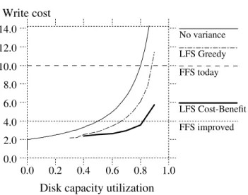
1.0 0.8 0.6 0.4 0.2 0.0 14.0 12.0 10.0 8.0 6.0 4.0 2.0 0.0
Disk capacity utilization Write cost LFS hot-and-cold LFS uniform FFS today FFS improved No variance
Figure 4 — Initial simulation results.
The curves labeled ‘‘FFS today’’ and ‘‘FFS improved’’ are repro-duced from Figure 3 for comparison. The curve labeled ‘‘No variance’’ shows the write cost that would occur if all segments always had exactly the same utilization. The ‘‘LFS uniform’’ curve represents a log-structuredfile system with uniform access pattern and a greedy cleaning policy: the cleaner chooses the least-utilized segments. The ‘‘LFS hot-and-cold’’ curve represents a log-structuredfile system with locality offile access. It uses a greedy cleaning policy and the cleaner also sorts the live data by age before writing it out again. The x-axis is overall disk capacity utilization, which is not necessarily the same as the utili-zation of the segments being cleaned.
Even with uniform random access patterns, the vari-ance in segment utilization allows a substantially lower write cost than would be predicted from the overall disk capacity utilization and formula (1). For example, at 75% overall disk capacity utilization, the segments cleaned have an average utilization of only 55%. At overall disk capa-city utilizations under 20% the write cost drops below 2.0; this means that some of the cleaned segments have no live blocks at all and hence don’t need to be read in.
The ‘‘LFS hot-and-cold’’ curve shows the write cost when there is locality in the access patterns, as described above. The cleaning policy for this curve was the same as for ‘‘LFS uniform’’ except that the live blocks were sorted by age before writing them out again. This means that long-lived (cold) data tends to be segregated in different segments from short-lived (hot) data; we thought that this approach would lead to the desired bimodal distribution of segment utilizations.
Figure 4 shows the surprising result that locality and ‘‘better’’ grouping result inworseperformance than a sys-tem with no locality! We tried varying the degree of local-ity (e.g. 95% of accesses to 5% of data) and found that per-formance got worse and worse as the locality increased. Figure 5 shows the reason for this non-intuitive result. Under the greedy policy, a segment doesn’t get cleaned until it becomes the least utilized of all segments. Thus every segment’s utilization eventually drops to the cleaning threshold, including the cold segments. Unfortunately, the
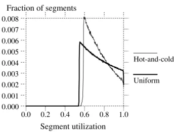
Fraction of segments Hot-and-cold Uniform Segment utilization 0.000 0.001 0.002 0.003 0.004 0.005 0.006 0.007 0.008 0.0 0.2 0.4 0.6 0.8 1.0
Figure 5 — Segment utilization distributions with greedy cleaner.
These figures show distributions of segment utilizations of the disk during the simulation. The distribution is computed by measuring the utilizations of all segments on the disk at the points during the simulation when segment cleaning was initiated. The distribution shows the utilizations of the segments available to the cleaning algorithm. Each of the distributions corresponds to an overall disk capacity utilization of 75%. The ‘‘Uniform’’ curve corresponds to ‘‘LFS uniform’’ in Figure 4 and ‘‘Hot-and-cold’’ corresponds to ‘‘LFS hot-and-cold’’ in Figure 4. Locality causes the distribution to be more skewed towards the utilization at which cleaning occurs; as a result, segments are cleaned at a higher average utilization.
utilization drops very slowly in cold segments, so these segments tend to linger just above the cleaning point for a very long time. Figure 5 shows that many more segments are clustered around the cleaning point in the simulations with locality than in the simulations without locality. The overall result is that cold segments tend to tie up large numbers of free blocks for long periods of time.
After studying thesefigures we realized that hot and cold segments must be treated differently by the cleaner. Free space in a cold segment is more valuable than free space in a hot segment because once a cold segment has been cleaned it will take a long time before it re-accumulates the unusable free space. Said another way, once the system reclaims the free blocks from a segment with cold data it will get to ‘‘keep’’ them a long time before the cold data becomes fragmented and ‘‘takes them back again.’’ In contrast, it is less beneficial to clean a hot segment because the data will likely die quickly and the free space will rapidly re-accumulate; the system might as well delay the cleaning a while and let more of the blocks die in the current segment. The value of a segment’s free space is based on the stability of the data in the segment. Unfortunately, the stability cannot be predicted without knowing future access patterns. Using an assumption that the older the data in a segment the longer it is likely to
remain unchanged, the stability can be estimated by the age of data.
To test this theory we simulated a new policy for selecting segments to clean. The policy rates each segment according to the benefit of cleaning the segment and the cost of cleaning the segment and chooses the segments with the highest ratio of benefit to cost. The benefit has two components: the amount of free space that will be reclaimed and the amount of time the space is likely to stay free. The amount of free space is just 1−u, whereuis the utilization of the segment. We used the most recent modified time of any block in the segment (ie. the age of the youngest block) as an estimate of how long the space is likely to stay free. The benefit of cleaning is the space-time product formed by multiplying these two components. The cost of cleaning the segment is 1+u(one unit of cost to read the segment,uto write back the live data). Combining all these factors, we get
cost benefit
= free space generated * age of datacost = (1−1u+)*ageu
We call this policy the cost-benefit policy; it allows cold segments to be cleaned at a much higher utilization than hot segments.
We re-ran the simulations under the hot-and-cold access pattern with the cost-benefit policy and age-sorting
LFS Cost-Benefit LFS Greedy Segment utilization 0.000 0.001 0.002 0.003 0.004 0.005 0.006 0.007 0.008 0.0 0.2 0.4 0.6 0.8 1.0 Fraction of segments
Figure 6 — Segment utilization distribution with cost-benefit policy.
Thisfigure shows the distribution of segment utilizations from the simulation of a hot-and-cold access pattern with 75% overall disk capacity utilization. The ‘‘LFS Cost-Benefit’’ curve shows the segment distribution occurring when the cost-benefit policy is used to select segments to clean and live blocks grouped by age before being re-written. Because of this bimodal segment distri-bution, most of the segments cleaned had utilizations around 15%. For comparison, the distribution produced by the greedy method selection policy is shown by the ‘‘LFS Greedy’’ curve reproduced from Figure 5.
on the live data. As can be seen from Figure 6, the cost-benefit policy produced the bimodal distribution of seg-ments that we had hoped for. The cleaning policy cleans cold segments at about 75% utilization but waits until hot segments reach a utilization of about 15% before cleaning them. Since 90% of the writes are to hotfiles, most of the segments cleaned are hot. Figure 7 shows that the cost-benefit policy reduces the write cost by as much as 50% over the greedy policy, and a log-structured file system out-performs the best possible Unix FFS even at relatively high disk capacity utilizations. We simulated a number of other degrees and kinds of locality and found that the cost-benefit policy gets even better as locality increases.
The simulation experiments convinced us to imple-ment the cost-benefit approach in Sprite LFS. As will be seen in Section 5.2, the behavior of actualfile systems in Sprite LFS is even better than predicted in Figure 7.
3.6. Segment usage table
In order to support the cost-benefit cleaning policy, Sprite LFS maintains a data structure called thesegment
usage table. For each segment, the table records the
number of live bytes in the segment and the most recent modified time of any block in the segment. These two values are used by the segment cleaner when choosing ments to clean. The values are initially set when the seg-ment is written, and the count of live bytes is decreseg-mented when files are deleted or blocks are overwritten. If the count falls to zero then the segment can be reused without cleaning. The blocks of the segment usage table are writ-ten to the log, and the addresses of the blocks are stored in
1.0 0.8 0.6 0.4 0.2 0.0 14.0 12.0 10.0 8.0 6.0 4.0 2.0 0.0
Disk capacity utilization Write cost LFS Greedy LFS Cost-Benefit FFS today FFS improved No variance
Figure 7 — Write cost, including cost-benefit policy.
This graph compares the write cost of the greedy policy with that of the cost-benefit policy for the hot-and-cold access pattern. The cost-benefit policy is substantially better than the greedy policy, particularly for disk capacity utilizations above 60%.
the checkpoint regions (see Section 4 for details).
In order to sort live blocks by age, the segment sum-mary information records the age of the youngest block written to the segment. At present Sprite LFS does not keep modified times for each block in afile; it keeps a sin-gle modified time for the entirefile. This estimate will be incorrect for files that are not modified in their entirety. We plan to modify the segment summary information to include modified times for each block.
4. Crash recovery
When a system crash occurs, the last few operations performed on the disk may have left it in an inconsistent state (for example, a new file may have been written without writing the directory containing the file); during reboot the operating system must review these operations in order to correct any inconsistencies. In traditional Unix
file systems without logs, the system cannot determine where the last changes were made, so it must scan all of the metadata structures on disk to restore consistency. The cost of these scans is already high (tens of minutes in typi-cal configurations), and it is getting higher as storage sys-tems expand.
In a log-structuredfile system the locations of the last disk operations are easy to determine: they are at the end of the log. Thus it should be possible to recover very quickly after crashes. This benefit of logs is well known and has been used to advantage both in database sys-tems[13] and in other file systems[2, 3, 14]. Like many other logging systems, Sprite LFS uses a two-pronged approach to recovery: checkpoints, which define consistent states of thefile system, androll-forward, which is used to recover information written since the last checkpoint.
4.1. Checkpoints
A checkpoint is a position in the log at which all of the file system structures are consistent and complete. Sprite LFS uses a two-phase process to create a checkpoint. First, it writes out all modified information to the log, including file data blocks, indirect blocks, inodes, and blocks of the inode map and segment usage table. Second, it writes acheckpoint region to a specialfixed position on disk. The checkpoint region contains the addresses of all the blocks in the inode map and segment usage table, plus the current time and a pointer to the last segment written.
During reboot, Sprite LFS reads the checkpoint region and uses that information to initialize its main-memory data structures. In order to handle a crash during a checkpoint operation there are actually two checkpoint regions, and checkpoint operations alternate between them. The checkpoint time is in the last block of the checkpoint region, so if the checkpoint fails the time will not be updated. During reboot, the system reads both checkpoint regions and uses the one with the most recent time.
Sprite LFS performs checkpoints at periodic intervals as well as when thefile system is unmounted or the system
is shut down. A long interval between checkpoints reduces the overhead of writing the checkpoints but increases the time needed to roll forward during recovery; a short checkpoint interval improves recovery time but increases the cost of normal operation. Sprite LFS currently uses a checkpoint interval of thirty seconds, which is probably much too short. An alternative to periodic checkpointing is to perform checkpoints after a given amount of new data has been written to the log; this would set a limit on recovery time while reducing the checkpoint overhead when the file system is not operating at maximum throughput.
4.2. Roll-forward
In principle it would be safe to restart after crashes by simply reading the latest checkpoint region and discard-ing any data in the log after that checkpoint. This would result in instantaneous recovery but any data written since the last checkpoint would be lost. In order to recover as much information as possible, Sprite LFS scans through the log segments that were written after the last checkpoint. This operation is calledroll-forward.
During roll-forward Sprite LFS uses the information in segment summary blocks to recover recently-writtenfile data. When a summary block indicates the presence of a new inode, Sprite LFS updates the inode map it read from the checkpoint, so that the inode map refers to the new copy of the inode. This automatically incorporates the
file’s new data blocks into the recovered file system. If data blocks are discovered for afile without a new copy of thefile’s inode, then the roll-forward code assumes that the new version of thefile on disk is incomplete and it ignores the new data blocks.
The roll-forward code also adjusts the utilizations in the segment usage table read from the checkpoint. The utilizations of the segments written since the checkpoint will be zero; they must be adjusted to reflect the live data left after roll-forward. The utilizations of older segments will also have to be adjusted to reflect file deletions and overwrites (both of these can be identified by the presence of new inodes in the log).
Thefinal issue in roll-forward is how to restore con-sistency between directory entries and inodes. Each inode contains a count of the number of directory entries refer-ring to that inode; when the count drops to zero thefile is deleted. Unfortunately, it is possible for a crash to occur when an inode has been written to the log with a new refer-ence count while the block containing the corresponding directory entry has not yet been written, or vice versa.
To restore consistency between directories and inodes, Sprite LFS outputs a special record in the log for each directory change. The record includes an operation code (create, link, rename, or unlink), the location of the directory entry (i-number for the directory and the position within the directory), the contents of the directory entry (name and i-number), and the new reference count for the inode named in the entry. These records are collectively
called the directory operation log; Sprite LFS guarantees that each directory operation log entry appears in the log before the corresponding directory block or inode.
During roll-forward, the directory operation log is used to ensure consistency between directory entries and inodes: if a log entry appears but the inode and directory block were not both written, roll-forward updates the direc-tory and/or inode to complete the operation. Roll-forward operations can cause entries to be added to or removed from directories and reference counts on inodes to be updated. The recovery program appends the changed direc-tories, inodes, inode map, and segment usage table blocks to the log and writes a new checkpoint region to include them. The only operation that can’t be completed is the creation of a newfile for which the inode is never written; in this case the directory entry will be removed. In addition to its other functions, the directory log made it easy to pro-vide an atomic rename operation.
The interaction between the directory operation log and checkpoints introduced additional synchronization issues into Sprite LFS. In particular, each checkpoint must represent a state where the directory operation log is con-sistent with the inode and directory blocks in the log. This required additional synchronization to prevent directory modifications while checkpoints are being written.
5. Experience with the Sprite LFS
We began the implementation of Sprite LFS in late 1989 and by mid-1990 it was operational as part of the Sprite network operating system. Since the fall of 1990 it has been used to manage five different disk partitions, which are used by about thirty users for day-to-day com-puting. All of the features described in this paper have been implemented in Sprite LFS, but roll-forward has not yet been installed in the production system. The produc-tion disks use a short checkpoint interval (30 seconds) and discard all the information after the last checkpoint when they reboot.
When we began the project we were concerned that a log-structuredfile system might be substantially more com-plicated to implement than a traditionalfile system. In real-ity, however, Sprite LFS turns out to be no more compli-cated than Unix FFS[9]: Sprite LFS has additional com-plexity for the segment cleaner, but this is compensated by the elimination of the bitmap and layout policies required by Unix FFS; in addition, the checkpointing and roll-forward code in Sprite LFS is no more complicated than thefsckcode[15] that scans Unix FFS disks to restore con-sistency. Loggingfile systems like Episode[2] or Cedar[3] are likely to be somewhat more complicated than either Unix FFS or Sprite LFS, since they include both logging and layout code.
In everyday use Sprite LFS does not feel much dif-ferent to the users than the Unix FFS-like file system in Sprite. The reason is that the machines being used are not fast enough to be disk-bound with the current workloads. For example on the modified Andrew benchmark[11],
(b) (a)
Files/sec (predicted) Files/sec (measured)
10000 1Kfile create 10000 1Kfile access Sun4 2*Sun4 4*Sun4
0 75 150 225 300 375 450 525 600 675
Create Read Delete 0 20 40 60 80 100 120 140 160 180 Sprite LFS SunOS Key:
Figure 8 — Small-file performance under Sprite LFS and SunOS.
Figure (a) measures a benchmark that created 10000 one-kilobyte files, then read them back in the same order as created, then delet-ed them. Spedelet-ed is measurdelet-ed by the number offiles per second for each operation on the twofile systems. The logging approach in Sprite LFS provides an order-of-magnitude speedup for creation and deletion. Figure (b) estimates the performance of each system for creating files on faster computers with the same disk. In SunOS the disk was 85% saturated in (a), so faster processors will not improve performance much. In Sprite LFS the disk was only 17% saturated in (a) while the CPU was 100% utilized; as a consequence I/O performance will scale with CPU speed.
Sprite LFS is only 20% faster that SunOS using the configuration presented in Section 5.1. Most of the speedup is attributable to the removal of the synchronous writes in Sprite LFS. Even with the synchronous writes of Unix FFS, the benchmark has a CPU utilization of over 80%, limiting the speedup possible from changes in the disk storage management.
5.1. Micro-benchmarks
We used a collection of small benchmark programs to measure the best-case performance of Sprite LFS and compare it to SunOS 4.0.3, whosefile system is based on Unix FFS. The benchmarks are synthetic so they do not represent realistic workloads, but they illustrate the strengths and weaknesses of the two file systems. The machine used for both systems was a Sun-4/260 (8.7 integer SPECmarks) with 32 megabytes of memory, a Sun SCSI3 HBA, and a Wren IV disk (1.3 MBytes/sec max-imum transfer bandwidth, 17.5 milliseconds average seek time). For both LFS and SunOS, the disk was formatted with afile system having around 300 megabytes of usable storage. An eight-kilobyte block size was used by SunOS while Sprite LFS used a four-kilobyte block size and a one-megabyte segment size. In each case the system was
running multiuser but was otherwise quiescent during the test. For Sprite LFS no cleaning occurred during the benchmark runs so the measurements represent best-case performance; see Section 5.2 below for measurements of cleaning overhead.
Figure 8 shows the results of a benchmark that creates, reads, and deletes a large number of small files. Sprite LFS is almost ten times as fast as SunOS for the create and delete phases of the benchmark. Sprite LFS is also faster for reading the files back; this is because the
files are read in the same order created and the log-structured file system packs the files densely in the log. Furthermore, Sprite LFS only kept the disk 17% busy dur-ing the create phase while saturatdur-ing the CPU. In contrast, SunOS kept the disk busy 85% of the time during the create phase, even though only about 1.2% of the disk’s potential bandwidth was used for new data. This means that the per-formance of Sprite LFS will improve by another factor of 4-6 as CPUs get faster (see Figure 8(b)). Almost no improvement can be expected in SunOS.
Although Sprite was designed for efficiency on workloads with many small file accesses, Figure 9 shows that it also provides competitive performance for large
files. Sprite LFS has a higher write bandwidth than SunOS in all cases. It is substantially faster for random writes because it turns them into sequential writes to the log; it is also faster for sequential writes because it groups many blocks into a single large I/O, whereas SunOS performs
SunOS Sprite LFS 900 800 700 600 500 400 300 200 100 0 Reread Read Write Read Write kilobytes/sec
Sequential Random Sequential
Figure 9 — Large-file performance under Sprite LFS and SunOS.
The figure shows the speed of a benchmark that creates a 100-Mbytefile with sequential writes, then reads thefile back sequen-tially, then writes 100 Mbytes randomly to the existingfile, then reads 100 Mbytes randomly from thefile, andfinally reads thefile sequentially again. The bandwidth of each of the five phases is shown separately. Sprite LFS has a higher write bandwidth and the same read bandwidth as SunOS with the exception of sequen-tial reading of afile that was written randomly.
individual disk operations for each block (a newer version of SunOS groups writes [16] and should therefore have performance equivalent to Sprite LFS). The read perfor-mance is similar in the two systems except for the case of reading a file sequentially after it has been written ran-domly; in this case the reads require seeks in Sprite LFS, so its performance is substantially lower than SunOS.
Figure 9 illustrates the fact that a log-structured file system produces a different form of locality on disk than traditionalfile systems. A traditional file system achieves
logical locality by assuming certain access patterns
(sequential reading offiles, a tendency to use multiplefiles within a directory, etc.); it then pays extra on writes, if necessary, to organize information optimally on disk for the assumed read patterns. In contrast, a log-structured file system achieves temporal locality: information that is created or modified at the same time will be grouped closely on disk. If temporal locality matches logical local-ity, as it does for afile that is written sequentially and then read sequentially, then a log-structuredfile system should have about the same performance on largefiles as a tradi-tionalfile system. If temporal locality differs from logical locality then the systems will perform differently. Sprite LFS handles random writes more efficiently because it writes them sequentially on disk. SunOS pays more for the random writes in order to achieve logical locality, but then it handles sequential re-reads more efficiently. Random reads have about the same performance in the two systems, even though the blocks are laid out very differently. How-ever, if the nonsequential reads occurred in the same order as the nonsequential writes then Sprite would have been much faster.
5.2. Cleaning overheads
The micro-benchmark results of the previous section give an optimistic view of the performance of Sprite LFS because they do not include any cleaning overheads (the
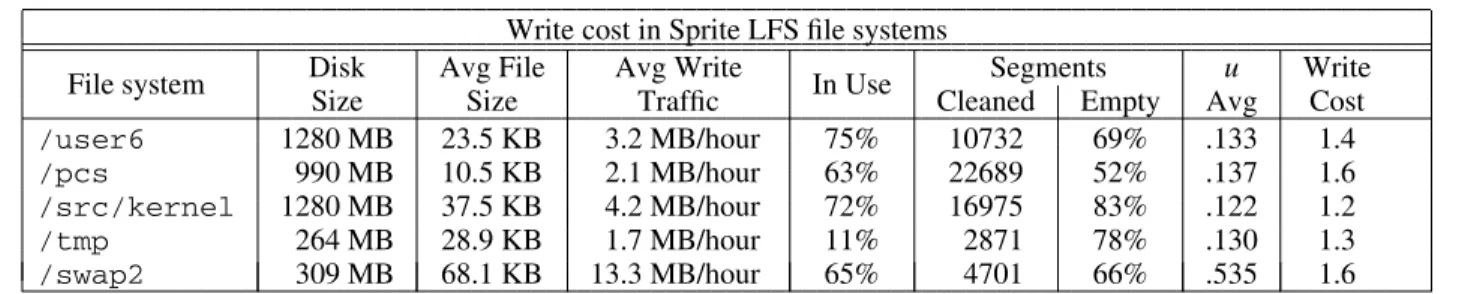
Write cost in Sprite LFSfile systems
Disk Avg File Avg Write Segments u Write
File system Size Size Traffic In Use Cleaned Empty Avg Cost
/user6 1280 MB 23.5 KB 3.2 MB/hour 75% 10732 69% .133 1.4 /pcs 990 MB 10.5 KB 2.1 MB/hour 63% 22689 52% .137 1.6 /src/kernel 1280 MB 37.5 KB 4.2 MB/hour 72% 16975 83% .122 1.2 /tmp 264 MB 28.9 KB 1.7 MB/hour 11% 2871 78% .130 1.3 /swap2 309 MB 68.1 KB 13.3 MB/hour 65% 4701 66% .535 1.6
Table 2 - Segment cleaning statistics and write costs for productionfile systems.
For each Sprite LFSfile system the table lists the disk size, the averagefile size, the average daily write traffic rate, the average disk capaci-ty utilization, the total number of segments cleaned over a four-month period, the fraction of the segments that were empcapaci-ty when cleaned, the average utilization of the non-empty segments that were cleaned, and the overall write cost for the period of the measurements. These write costfigures imply that the cleaning overhead limits the long-term write performance to about 70% of the maximum sequential write bandwidth.
write cost during the benchmark runs was 1.0). In order to assess the cost of cleaning and the effectiveness of the cost-benefit cleaning policy, we recorded statistics about our production log-structured file systems over a period of several months. Five systems were measured:
/user6 Home directories for Sprite developers. Work-load consists of program development, text pro-cessing, electronic communication, and simula-tions.
/pcs Home directories and project area for research on parallel processing and VLSI circuit design. /src/kernel
Sources and binaries for the Sprite kernel. /swap2 Sprite client workstation swap files. Workload
consists of virtual memory backing store for 40 diskless Sprite workstations. Files tend to be large, sparse, and accessed nonsequentially. /tmp Temporaryfile storage area for 40 Sprite
works-tations.
Table 2 shows statistics gathered during cleaning over a four-month period. In order to eliminate start-up effects we waited several months after putting thefile sys-tems into use before beginning the measurements. The behavior of the production file systems has been substan-tially better than predicted by the simulations in Section 3. Even though the overall disk capacity utilizations ranged from 11-75%, more than half of the segments cleaned were totally empty. Even the non-empty segments have utiliza-tions far less than the average disk utilizautiliza-tions. The overall write costs ranged from 1.2 to 1.6, in comparison to write costs of 2.5-3 in the corresponding simulations. Figure 10 shows the distribution of segment utilizations, gathered in a recent snapshot of the /user6disk.
We believe that there are two reasons why cleaning costs are lower in Sprite LFS than in the simulations. First,
all thefiles in the simulations were just a single block long. In practice, there are a substantial number of longerfiles, and they tend to be written and deleted as a whole. This results in greater locality within individual segments. In the best case where afile is much longer than a segment, deleting the file will produce one or more totally empty segments. The second difference between simulation and reality is that the simulated reference patterns were evenly distributed within the hot and coldfile groups. In practice there are large numbers offiles that are almost never writ-ten (cold segments in reality are much colder than the cold segments in the simulations). A log-structuredfile system will isolate the very coldfiles in segments and never clean them. In the simulations, every segment eventually received modifications and thus had to be cleaned.
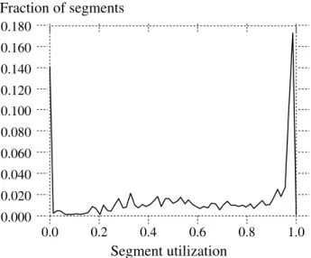
If the measurements of Sprite LFS in Section 5.1 were a bit over-optimistic, the measurements in this section are, if anything, over-pessimistic. In practice it may be possible to perform much of the cleaning at night or during other idle periods, so that clean segments are available dur-ing bursts of activity. We do not yet have enough experi-ence with Sprite LFS to know if this can be done. In addi-tion, we expect the performance of Sprite LFS to improve as we gain experience and tune the algorithms. For exam-ple, we have not yet carefully analyzed the policy issue of how many segments to clean at a time, but we think it may impact the system’s ability to segregate hot data from cold data. Segment utilization 0.000 0.020 0.040 0.060 0.080 0.100 0.120 0.140 0.160 0.180 0.0 0.2 0.4 0.6 0.8 1.0 Fraction of segments
Figure 10 — Segment utilization in the /user6file system
Thisfigure shows the distribution of segment utilizations in a re-cent snapshot of the /user6disk. The distribution shows large numbers of fully utilized segments and totally empty segments.
5.3. Crash recovery
Although the crash recovery code has not been installed on the production system, the code works well enough to time recovery of various crash scenarios. The time to recover depends on the checkpoint interval and the rate and type of operations being performed. Table 3 shows the recovery time for differentfile sizes and amounts of file data recovered. The different crash configurations were generated by running a program that created one, ten, orfifty megabytes offixed-sizefiles before the system was crashed. A special version of Sprite LFS was used that had an infinite checkpoint interval and never wrote directory changes to disk. During the recovery roll-forward, the createdfiles had to be added to the inode map, the directory entries created, and the segment usage table updated.
Table 3 shows that recovery time varies with the number and size of files written between the last check-point and the crash. Recovery times can be bounded by limiting the amount of data written between checkpoints. From the average file sizes and daily write traffic in Table 2, a checkpoint interval as large as an hour would result in average recovery times of around one second. Using the maximum observered write rate of 150 megabytes/hour, maximum recovery time would grow by one second for every 70 seconds of checkpoint interval length.
5.4. Other overheads in Sprite LFS
Table 4 shows the relative importance of the various kinds of data written to disk, both in terms of how much of the live blocks they occupy on disk and in terms of how much of the data written to the log they represent. More than 99% of the live data on disk consists of file data blocks and indirect blocks. However, about 13% of the information written to the log consists of inodes, inode map blocks, and segment map blocks, all of which tend to be overwritten quickly. The inode map alone accounts for more than 7% of all the data written to the log. We suspect that this is because of the short checkpoint interval currently used in Sprite LFS, which forces metadata to disk
Sprite LFS recovery time in seconds
File File Data Recovered
Size 1 MB 10 MB 50 MB 1 KB 1 21 132 10 KB < 1 3 17 100 KB < 1 1 8
Table 3 — Recovery time for various crash configurations
The table shows the speed of recovery of one, ten, andfifty mega-bytes offixed-sizefiles. The system measured was the same one used in Section 5.1. Recovery time is dominated by the number of files to be recovered.
more often than necessary. We expect the log bandwidth overhead for metadata to drop substantially when we install roll-forward recovery and increase the checkpoint interval.
6. Related work
The log-structuredfile system concept and the Sprite LFS design borrow ideas from many different storage management systems. File systems with log-like structures have appeared in several proposals for buildingfile systems on write-once media[17, 18]. Besides writing all changes in an append-only fashion, these systems maintain indexing information much like the Sprite LFS inode map and inodes for quickly locating and reading files. They differ from Sprite LFS in that the write-once nature of the media made it unnecessary for the file systems to reclaim log space.
The segment cleaning approach used in Sprite LFS acts much like scavenging garbage collectors developed for programming languages[19]. The cost-benefit segment selection and the age sorting of blocks during segment cleaned in Sprite LFS separatesfiles into generations much like generational garbage collection schemes[20]. A significant difference between these garbage collection schemes and Sprite LFS is that efficient random access is possible in the generational garbage collectors, whereas sequential accesses are necessary to achieve high perfor-mance in a file system. Also, Sprite LFS can exploit the fact that blocks can belong to at most onefile at a time to use much simpler algorithms for identifying garbage than used in the systems for programming languages.
The logging scheme used in Sprite LFS is similar to schemes pioneered in database systems. Almost all data-base systems use write-ahead logging for crash recovery and high performance[13], but differ from Sprite LFS in how they use the log. Both Sprite LFS and the database
Sprite LFS/user6file system contents
Block type Live data Log bandwidth
Data blocks* 98.0% 85.2% Indirect blocks* 1.0% 1.6% Inode blocks* 0.2% 2.7% Inode map 0.2% 7.8%
Seg Usage map* 0.0% 2.1%
Summary blocks 0.6% 0.5% Dir Op Log 0.0% 0.1%
Table 4 — Disk space and log bandwidth usage of /user6
For each block type, the table lists the percentage of the disk space in use on disk (Live data) and the percentage of the log bandwidth consumed writing this block type (Log bandwidth). The block types marked with ’*’ have equivalent data structures in Unix FFS.
systems view the log as the most up to date ‘‘truth’’ about the state of the data on disk. The main difference is that database systems do not use the log as the final repository for data: a separate data area is reserved for this purpose. The separate data area of these database systems means that they do not need the segment cleaning mechanisms of the Sprite LFS to reclaim log space. The space occupied by the log in a database system can be reclaimed when the logged changes have been written to their final locations. Since all read requests are processed from the data area, the log can be greatly compacted without hurting read perfor-mance. Typically only the changed bytes are written to database logs rather than entire blocks as in Sprite LFS.
The Sprite LFS crash recovery mechanism of check-points and roll forward using a ‘‘redo log’’ is similar to techniques used in database systems and object reposi-tories[21]. The implementation in Sprite LFS is simplified because the log is the final home of the data. Rather than redoing the operation to the separate data copy, Sprite LFS recovery insures that the indexes point at the newest copy of the data in the log.
Collecting data in thefile cache and writing it to disk in large writes is similar to the concept of group commit in database systems[22] and to techniques used in main-memory database systems[23, 24].
7. Conclusion
The basic principle behind a log-structuredfile sys-tem is a simple one: collect large amounts of new data in a
file cache in main memory, then write the data to disk in a single large I/O that can use all of the disk’s bandwidth. Implementing this idea is complicated by the need to main-tain large free areas on disk, but both our simulation analysis and our experience with Sprite LFS suggest that low cleaning overheads can be achieved with a simple pol-icy based on cost and benefit. Although we developed a log-structured file system to support workloads with many smallfiles, the approach also works very well for large-file accesses. In particular, there is essentially no cleaning overhead at all for very large files that are created and deleted in their entirety.
The bottom line is that a log-structured file system can use disks an order of magnitude more efficiently than existingfile systems. This should make it possible to take advantage of several more generations of faster processors before I/O limitations once again threaten the scalability of computer systems.
8. Acknowledgments
Diane Greene, Mary Baker, John Hartman, Mike Kupfer, Ken Shirriff and Jim Mott-Smith provided helpful comments on drafts of this paper.
References
1. John K. Ousterhout, Herve Da Costa, David Harrison, John A. Kunze, Mike Kupfer, and James
![Figure 3 graphs the write cost as a function of u. For reference, Unix FFS on small-file workloads utilizes at most 5-10% of the disk bandwidth, for a write cost of 10-20 (see [11] and Figure 8 in Section 5.1 for specific measurements)](https://thumb-us.123doks.com/thumbv2/123dok_us/9380388.2421857/6.918.481.829.596.846/function-reference-workloads-utilizes-bandwidth-section-specific-measurements.webp)