Issue Date October 20, 2008
FX16 Master Controller
The FX16 Master Controller is a high performance field controller designed specifically for commercial Heating, Ventilating, Air Conditioning, and
Refrigeration (HVACR) applications.
The FX16 supports 27 physical inputs and outputs, including a wide range of sensors and actuating devices. You can add up to 72 physical inputs and outputs to the controller using I/O extension modules. The FX16 can manage a distributed control application with up to 16 slave FX controllers. The FX16 can also monitor and control a number of N2 Open compatible devices through its gateway feature.
Multiple user interface options allow you to monitor and/or adjust the FX16’s operation, either locally or remotely.
The FX16 can be fitted with an N2 Open,
LONWORKS®, or BACnet® communication card to integrate the controller into a compatible Building Automation System (BAS). Alternatively, the FX16 can be fitted with an RS-232C serial communication card to transmit event notification messages via email or Short Messaging Service (SMS) through a Global System for Mobile Communications (GSM) modem. With its onboard Web server, you can browse and make adjustments to the application from a remote location.
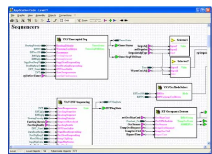
Using the FX Tools Pro software package, you can program the FX16 Master Controller to operate a wide range of commercial HVAC and refrigeration
equipment such as chillers, air handling units (AHUs), and close control units, as well as small distributed control systems with terminal units.
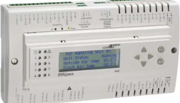
Figure 1: FX16 Master Controller
Features and Benefits Optional Integral or Remote User
Interfaces (UIs)
Provide a clear presentation of control system data on a menu-driven, scrolling, 4-line by 26-character Liquid Crystal Display (LCD) with backlight.
Distributed Control Application Provides the ability to control complex systems by coordinating the activities of multiple controllers in a single application.
Embedded Web Server Allows remote access to the data in the control system via a Web browser and modem connection to the FX16 Master Controller.
Communication Services Provide automatic reporting of events and alarms by e-mail or by SMS with optional acknowledgement.
Network Communications Options – N2 Open, LONWORKS,or BACnet Protocol
Provide a cost-effective method for stand-alone or networked operation.
Features and Benefits (Cont.) Freely Programmable or
Configurable Using FX Tools Pro
Enables a wide range of applications for HVAC or refrigeration control using the extensive programming features of the FX Tools Pro software package.
Onboard Trend and Event Logging
Provide the necessary information for analyzing the control system performance and diagnosing fault conditions.
Analog Input Types Selected in Software
Allow choice of temperature and other sensors according to the control range and application.
Onboard Inputs and Outputs (I/Os)
You can connect up to 27 physical inputs and outputs to the FX16 Master Controller, including:
• 6 Analog Inputs (AIs) – software configurable
• 8 Digital (Binary) Inputs (DIs) – for voltage free contacts
• 9 Digital (Binary) Outputs (DOs)
FX16 Master Controller Product Bulletin 3
− − − − − • − − − − • −
9 relays with 230 VAC contacts or
4 relays and 5 opto-isolated triacs for 24 VAC
• 4 Analog Outputs (AOs) – 0 to 10 VDC
I/O Modules
You can extend the input/output capacity of the FX16 Master Controller by connecting up to four XM07 I/O modules or two XM14 I/O modules via the Local Link Bus. The FX16 also supports up to four System 91 XT/XP extension modules.
FX I/O Modules
XM07:
• 5 Universal Inputs (UIs) - software configurable as AI or DI
• 4 Digital (Binary) Inputs (DIs) - for voltage free contacts
• 6 Digital (Binary) Outputs (DOs) 6 relays with 230 VAC contacts or
4 relays and 2 opto-isolated triacs for 24 VAC or 230 VAC (model dependent)
manual override on 4 outputs (option)
3 Analog Outputs (AOs) - 0 to 10 VDC manual override on 2 outputs (option) XM14:
• 6 Universal Inputs (UIs) - software configurable as AI or DI
• 12 Digital (Binary) Inputs (DIs) - for voltage free contacts
• 9 Digital (Binary) Outputs (DOs) 9 relays with 230 VAC contacts or
5 relays and 4 opto-isolated triacs for 24 VAC or 230 VAC (model dependent)
manual override on 7 outputs (option)
4 Analog Outputs (AOs) - 0 to 10 VDC manual override on 3 outputs (option)
System 91 I/O Modules
The XT extension module supports XP expansion modules with the following inputs and outputs:
• XT91D00 Processor/communication module
• XP91D02 6 AIs and 2 AOs
• XP91D03 8 DOs (triacs) 24 VAC
• XP91D04 4 DIs + 4 DOs (triacs) 24 VAC
• XP91D05 8 DIs
• XP91D06 4 DOs (relays) 230 VAC (Europe only)
• XP91D07 4 DOs (relays) 24 VAC (North America only)
Embedded Web Server and Web
Page Access
The FX16 Master Controller features an embedded Web server that enables a local or remote user to establish communication with the FX16 Master Controller from a computer. You can also view live control data, active alarms and events, trend data, and configuration parameters. The Web server provides an effective, low-cost monitoring system without the need for any special or proprietary supervisory software. To access the Web pages, you use a direct serial line or telephone modem connection and the Point-to-Point Protocol (PPP) from any computer with Microsoft® Internet Explorer® software that serves as a Web browser.
The FX16 Master Controller provides the formatted data for the requested pages starting with a home page (where you can request other pages). Each page may contain graphic images, links to the other pages, and data windows for the display of live data from the control system.
The embedded Web server in the FX16 Master Controller transmits the active values to the screen on the computer. Typically, up to 16 values can be continuously updated on one page. If necessary, you may adjust or override values on the screen. To prevent unauthorized data access and control actions, a password system protects access to the Web pages. The Web server interface provides the following features from any computer that directly connects to the FX16 Master Controller or that has access to the telephone system. The Web server interface:
• displays live variables in the monitored control system
• adjusts and commands variables in the control system
• displays and acknowledges active alarms
• displays the event history log
• displays trended data values that can be copied/pasted to a Microsoft Excel spreadsheet for storage and further processing
• enables and disables trend logs
• reads and modifies communication parameters including e-mail addresses, telephone numbers, and others
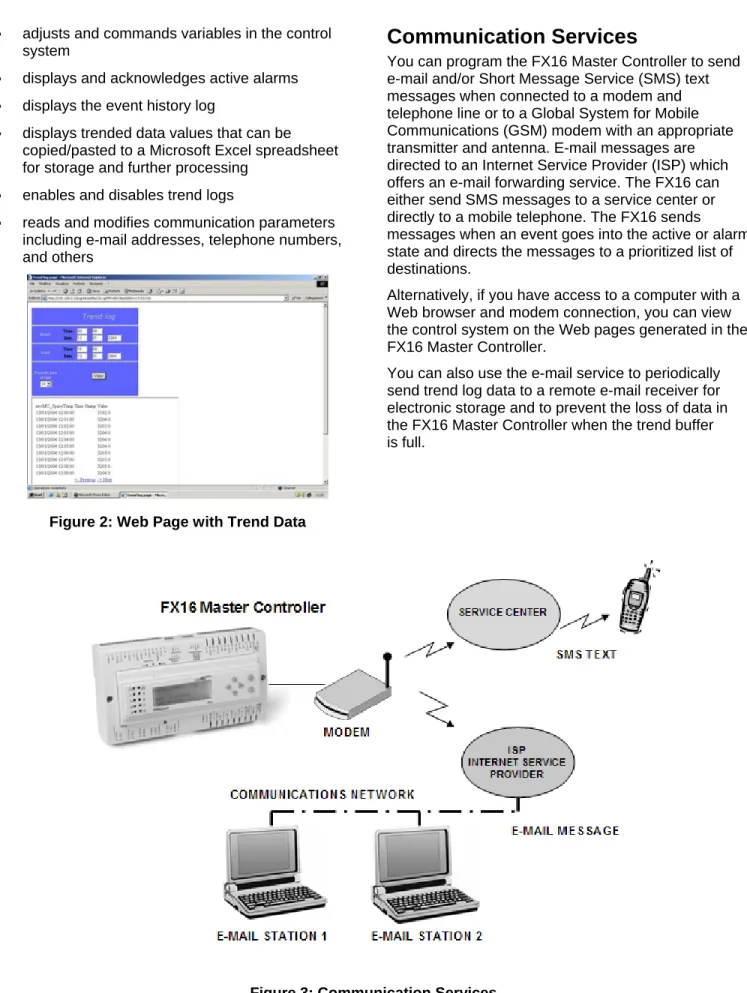
Figure 2: Web Page with Trend Data
Communication Services
You can program the FX16 Master Controller to send e-mail and/or Short Message Service (SMS) text messages when connected to a modem and telephone line or to a Global System for Mobile Communications (GSM) modem with an appropriate transmitter and antenna. E-mail messages are directed to an Internet Service Provider (ISP) which offers an e-mail forwarding service. The FX16 can either send SMS messages to a service center or directly to a mobile telephone. The FX16 sends messages when an event goes into the active or alarm state and directs the messages to a prioritized list of destinations.
Alternatively, if you have access to a computer with a Web browser and modem connection, you can view the control system on the Web pages generated in the FX16 Master Controller.
You can also use the e-mail service to periodically send trend log data to a remote e-mail receiver for electronic storage and to prevent the loss of data in the FX16 Master Controller when the trend buffer is full.
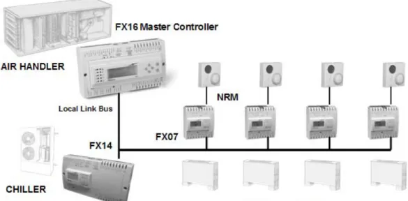
Distributed Application
A distributed application is a control strategy managed by the FX16 Master Controller but executed
concurrently in the FX16 Master Controller and in up to 16 FX slave controllers connected to the Local Link Bus. Network variables define the communication between the controllers in the distributed application, and the FX16 Master Controller executes the
communication in the most effective way to maintain the performance of the entire control system. Distributed applications are used for the coordinated control of a central plant and for the remote equipment that the plant serves. For example, you can apply a distributed application to an FX16 Master Controller controlling an air handling unit, an FX14 controller controlling a chiller unit, and a number of FX07 controllers controlling zone terminal units or fan coil units.
Another benefit of a distributed application is the ability to combine FX controllers to achieve the inputs and outputs required for the physical equipment interface. The application is automatically distributed and executed in the individual controllers forming a single control system.
Gateway Feature
The latest versions of the FX16X Master Controller feature a Gateway object. The Gateway object allows the FX16 to monitor up to 16 N2 Open devices which are not slaves in a distributed application on the Local Link Bus. These devices can be FX controllers fitted with an N2 Open communication card, Metasys® Application Specific Controllers (ASCs) (UNT, Variable Air Volume [VAV], AHU), Metasys system compatible N2 Open Vendor (VND) devices, or System 91 N2 devices (DX-9100 and TC-910x).
Figure 4: Distributed Application
Communication Card Options
The FX16 can operate as a stand-alone controller, or it can be fitted with a communication card to provide various types of remote network access. The FX16 supports N2 Open, LONWORKS, BACnet Master Slave/Token-Passing (MS/TP), or RS-232C networking communication card options.
N2 Open Communication Card
When fitted with an N2 Open communication card, the FX16 controller can connect to the N2 bus of a compatible supervisory controller. This connection allows network access to the controller’s control system variables and parameters.
L
ONW
ORKSCommunication Card
When fitted with a LONWORKS communication card, the FX16 can integrate into a LONWORKS network. This integration allows peer-to-peer communication with other LONWORKS compatible devices on the network and data access from a supervisory system.
BACnet MS/TP Communication Card
When fitted with a BACnet MS/TP communication card, the FX16 can connect to a BACnet compliant BAS. This connection allows network access to the FX16 control system variables and parameters. The FX16 controller supports peer-to-peer communication with other controllers on the BACnet network and change-of-value reporting to monitoring stations.
RS-232C Serial Communication Card
When fitted with an RS-232C serial communication card, the FX16 can connect to a Global System for Mobile Communications (GSM) modem. When an application event goes into the active or alarm state, the FX16 sends out text messages in SMS format to a prioritized list of destinations, such as to a telephone service center or directly to a mobile telephone. The RS-232C serial card also supports point-to-point connections to a computer using GSM or landline modems.
Real-Time Control
The FX16 has an embedded real-time clock that supports real-time control functions such as the display of time and date on the user interface, scheduling, and event and trend management. The real-time clock is battery-backed with an average battery life of more than 3 years.
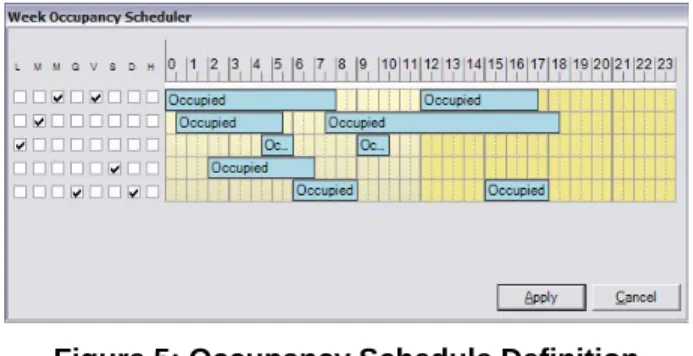
Scheduling
The real-time clock enables the time scheduling of start, stop, and occupancy commands for the plant you want to monitor and control. You can configure scheduled commands to execute on 1 or more days of the week. An exception day calendar allows for alternate time schedules on holidays or during special periods in the year.
You can view and edit time schedules on the available user interfaces or in a Web page.
Figure 5: Occupancy Schedule Definition
Event Management
The real-time clock enables the time stamping of alarm and event records. You can configure the FX16 to detect and display events and alarms generated by the operating system. The FX16 also manages and generates events or alarms associated with data points or variables in the control application. System events indicate that the control system requires some attention and include events such as:
• system powerup
• trend buffer full
• communication message failure (e-mail, SMS)
• device communication error
• application or display diagnostic error Application events or alarms indicate that the controlled equipment requires attention or that the controlled conditions are not within the expected limits. For example:
• The analog value is outside of a desired range.
• The status value represents an abnormal condition.
When an event goes into the active state, the FX16 enters the event into the table of active events and the event history log with the time and date of occurrence. A message window appears on the display screen. You can also configure the event to send a text message to one or more of the following:
• e-mail message server
• mobile telephone with Short Message Service (SMS)
The system only removes the events from the table of active events when you acknowledge the event and the event returns to an inactive or normal state. You can acknowledge events from any of the connected user interfaces. Displays and the Web page have password protection. You can view the table of active events and the event history log on the integral or remote displays, or on the Web browser screen.
FX16 Master Controller Product Bulletin 7
Trend Management
The real-time clock enables the time stamping of trend records.You can configure the FX16 Master Controller to record data samples at a defined interval for up to 40 variables within the control application. The sample interval is defined for each variable and can be set from once per minute to once per day. In the latest LP-FX16X Rev. A or B versions, the onboard memory can store trend log samples from 40 variables at 15-minute intervals for up to 100 days.
You can view trend data for each variable within a specified time period in text format on the connected user displays. You can also view trend log data from a Web browser; this allows you to copy and paste trend information into a spreadsheet application, such as Excel, for further processing and electronic storage. You can transmit trend logs at regular intervals, from 1 hour to every day, via the connection between a telephone modem and e-mail server. You can also upload trend data with FX CommPro. FX CommPro then converts the data into a standard format for transfer to a computer.
A system event message is generated if the trend buffer is not configured in the circular recording mode and the buffer becomes full.
User Interfaces
The FX16 Master Controller supports two user interfaces, which can be integral and remote. These user interfaces feature a 4 line by 26 character LCD, 6 push buttons, and 10 discrete status Light-Emitting Diodes (LEDs). The display and navigation menus are fully programmable within the control application using FX Builder.
The integral Medium User Interface (MUI) is built into the front face of the FX16. The MUI allows direct access to the points of the control system. You can order the FX16 models with and without the integral MUI.
Two versions of the remote Medium User Interface are available for panel or wall mounting:
• Panel Mount: Mounts up to up to 3 m (9.8 ft) from the FX16. The FX16 powers and operates this user interface. A flat telephone cable is available to connect the power supply and data
communications to the FX16 controller.
• Wall Mount: Mounts up to 300 m (1,000 ft) from the FX16. The wall mount user interface must be independently powered with 24 VAC. The data communication requires a 3-wire shielded cable (not provided) for the connection from the remote display to the FX16 controller. You can also panel mount this unit.
Figure 6: Remote Medium User Interface
Multi-language Database
All the text on the available user interfaces is fully programmable. You can enter the text in up to five different languages.
You can then select the preferred language from the display menu when you log into the system. This feature has been designed for systems intended for installation in many countries in the world or for areas where more than one language is spoken.
FX Tools Pro Software
Use the FX Tools Pro software suite to program, download, test, and commission the FX devices, including the FX16.
FX Tools Pro CD includes:
• FX Builder – used to fully program an FX16. FX Builder provides complete flexibility in programming the FX16.
• FX CommPro N2 – used to download, test, and commission an FX16 on an N2 Open network.
• FX CommPro LON – used to download, test, and commission an FX16 on a LONWORKS network.
• FX CommPro BACnet – used to download, test, and commission an FX16 on a BACnet network.
Application Upload/Download
With the FX16, you can download and upload a full application file to and from the latest LP-FX16X Rev. A (N2) or LP-FX16X Rev. B (BACnet) versions using a computer with the FX CommPro N2 or BACnet tool software. This way, the controller contains all the information for you to retrieve, view, and modify the application in FX Builder, if the archived version of the file is not available.
Dimensions
179 (7.05)
44
(
1
.7
3
)
75
(2
.9
5)
215 (8.46)
12
2 (4
.8)
14
2 (5
.59
)
35
(1
.3
8)
66 (2.6)
49 (1.93)
B
B
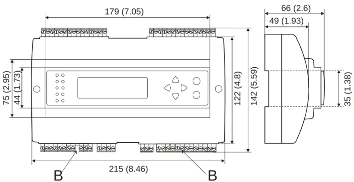
Figure 8: FX16 Master Controller Dimensions, mm (in.)
Ordering Codes
Table 1: FX16 Master Controller - Standard Temperature Range Product Code
Number
Description
LP-FX16D00-000C FX16, 6 AIs, 8 DIs, 4 AOs, 9 DOs (9 relays), no communication card LP-FX16D01-000C FX16, 6 AIs, 8 DIs, 4 AOs, 9 DOs (9 relays), N2 Open card
LP-FX16D02-000C FX16, 6 AIs, 8 DIs, 4 AOs, 9 DOs (9 relays), LON card LP-FX16D03-000C FX16, 6 AIs, 8 DIs, 4 AOs, 9 DOs (9 relays), RS-232C card
LP-FX16D10-000C FX16, 6 AIs, 8 DIs, 4 AOs, 9 DOs (4 relays, 5 triacs), no communication card LP-FX16D11-000C FX16, 6 AIs, 8 DIs, 4 AOs, 9 DOs (4 relays, 5 triacs), N2 Open card
LP-FX16D12-000C FX16, 6 AIs, 8 DIs, 4 AOs, 9 DOs (4 relays, 5 triacs), LON card
LP-FX16D13-000C FX16, 6 AIs, 8 DIs, 4 AOs, 9 DOs (4 relays, 5 triacs), RS-232C communication card
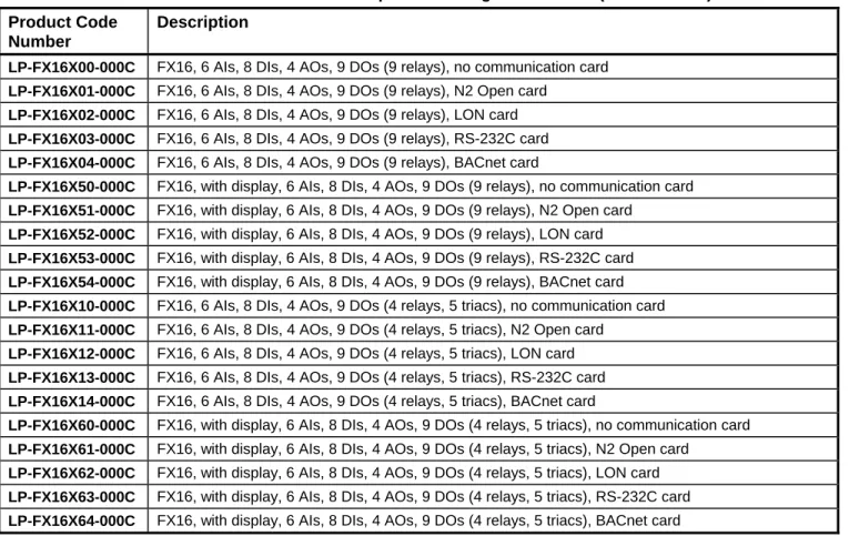
Table 2: FX16 Master Controller - Extended Temperature Range Controllers (Rev. A and B) Product Code
Number
Description
LP-FX16X00-000C FX16, 6 AIs, 8 DIs, 4 AOs, 9 DOs (9 relays), no communication card LP-FX16X01-000C FX16, 6 AIs, 8 DIs, 4 AOs, 9 DOs (9 relays), N2 Open card
LP-FX16X02-000C FX16, 6 AIs, 8 DIs, 4 AOs, 9 DOs (9 relays), LON card LP-FX16X03-000C FX16, 6 AIs, 8 DIs, 4 AOs, 9 DOs (9 relays), RS-232C card LP-FX16X04-000C FX16, 6 AIs, 8 DIs, 4 AOs, 9 DOs (9 relays), BACnet card
LP-FX16X50-000C FX16, with display, 6 AIs, 8 DIs, 4 AOs, 9 DOs (9 relays), no communication card LP-FX16X51-000C FX16, with display, 6 AIs, 8 DIs, 4 AOs, 9 DOs (9 relays), N2 Open card
LP-FX16X52-000C FX16, with display, 6 AIs, 8 DIs, 4 AOs, 9 DOs (9 relays), LON card LP-FX16X53-000C FX16, with display, 6 AIs, 8 DIs, 4 AOs, 9 DOs (9 relays), RS-232C card LP-FX16X54-000C FX16, with display, 6 AIs, 8 DIs, 4 AOs, 9 DOs (9 relays), BACnet card LP-FX16X10-000C FX16, 6 AIs, 8 DIs, 4 AOs, 9 DOs (4 relays, 5 triacs), no communication card LP-FX16X11-000C FX16, 6 AIs, 8 DIs, 4 AOs, 9 DOs (4 relays, 5 triacs), N2 Open card
LP-FX16X12-000C FX16, 6 AIs, 8 DIs, 4 AOs, 9 DOs (4 relays, 5 triacs), LON card LP-FX16X13-000C FX16, 6 AIs, 8 DIs, 4 AOs, 9 DOs (4 relays, 5 triacs), RS-232C card LP-FX16X14-000C FX16, 6 AIs, 8 DIs, 4 AOs, 9 DOs (4 relays, 5 triacs), BACnet card
LP-FX16X60-000C FX16, with display, 6 AIs, 8 DIs, 4 AOs, 9 DOs (4 relays, 5 triacs), no communication card LP-FX16X61-000C FX16, with display, 6 AIs, 8 DIs, 4 AOs, 9 DOs (4 relays, 5 triacs), N2 Open card
LP-FX16X62-000C FX16, with display, 6 AIs, 8 DIs, 4 AOs, 9 DOs (4 relays, 5 triacs), LON card LP-FX16X63-000C FX16, with display, 6 AIs, 8 DIs, 4 AOs, 9 DOs (4 relays, 5 triacs), RS-232C card LP-FX16X64-000C FX16, with display, 6 AIs, 8 DIs, 4 AOs, 9 DOs (4 relays, 5 triacs), BACnet card
Table 3: FX16 Communications Cards (for Upgrade or Replacement) Product Code
Number
Description
LP-NET151-010C N2 Open communication card for LP-FX16D and LP-FX16X (not Rev. A or B) controllers LP-NET161-000C N2 Open communication card for LP-FX16X Rev. A controllers
LP-NET152-010C LON communication card for LP-FX16 controllers LP-NET163-000C RS-232C communication card for LP-FX16 controllers LP-NET164-000C BACnet communication card for LP-FX16X Rev. B controllers
Table 4: User Interfaces Product Code
Number
Description
LP-DIS60P20-0C Medium User Interface for FX16 (non-isolated version); can be mounted up to 3 m (9.8 ft) from the FX16 and includes panel mounting hardware.
LP-DIS60P21-0C Medium User Interface for FX16 (isolated version); can be mounted up to 300 m (1,000 ft) from the FX16 and includes panel and wall mounting hardware.
Table 5: Accessories Product Code Number
Description
LP-KIT007-000C Interface cable 3 m (9.8 ft) for Medium User Interface (LP-DIS60P20-0C) to FX16 LP-KIT007-001C Interface cable for standard modem to FX16
LP-KIT007-013C Null modem cable, 3 m (9.8 ft) LP-KIT007-014C Null modem cable, 15 m (49 ft)
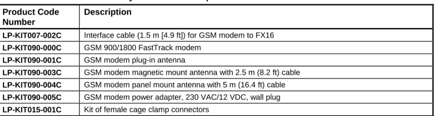
Table 6: FX16 Accessories - Only Available in Europe Product Code
Number
Description
LP-KIT007-002C Interface cable (1.5 m [4.9 ft]) for GSM modem to FX16 LP-KIT090-000C GSM 900/1800 FastTrack modem
LP-KIT090-001C GSM modem plug-in antenna
LP-KIT090-003C GSM modem magnetic mount antenna with 2.5 m (8.2 ft) cable LP-KIT090-004C GSM modem panel mount antenna with 5 m (16.4 ft) cable LP-KIT090-005C GSM modem power adapter, 230 VAC/12 VDC, wall plug LP-KIT015-001C Kit of female cage clamp connectors
Table 7: XM07 I/O Modules - 24 VAC Power Supply Product Code Description
LP-XM07X01-000C FX I/O Module 5 UI, 4 BI, 3 AO, 6 Relay DO, 24 VAC power supply
LP-XM07X11-000C FX I/O Module 5 UI, 4 BI, 3 AO, 2 Triac DO, 4 Relay DO, 24 VAC power supply LP-XM07X51-000C FX I/O Module 5 UI, 4 BI, 3 AO, 6 Relay DO, 24 VAC power supply
Manual Overrides for 2 AO and 4 Relay DO
LP-XM07X61-000C FX I/O Module 5 UI, 4 BI, 3 AO, 2 Triac DO, 4 Relay DO, 24 VAC power supply Manual Overrides for 2 AO, 2 Triac DO and 2 Relay DO
Table 8: XM07 I/O Modules - 90 to 240 VAC Power Supply (Not Available in North America) Product Code Description
LP-XM07B01-000C FX I/O Module 5 UI, 4 BI, 3 AO, 6 Relay DO, 90-240 VAC power supply
LP-XM07B11-000C FX I/O Module 5 UI, 4 BI, 3 AO, 2 Triac DO, 4 Relay DO, 90-240 VAC power supply LP-XM07B51-000C FX I/O Module 5 UI, 4 BI, 3 AO, 6 Relay DO, 90-240 VAC power supply
Manual Overrides for 2 AO and 4 Relay DO
LP-XM07B61-000C FX I/O Module 5 UI, 4 BI, 3 AO, 2 Triac DO, 4 Relay DO, 90-240 VAC power supply Manual Overrides for 2 AO, 2 Triac DO and 2 Relay DO
Table 9: XM14 I/O Modules - 24 VAC Power Supply Product Code Description
LP-XM14X01-000C FX I/O Module 6 UI, 12 BI, 4 AO, 9 Relay DO, 24 VAC power supply
LP-XM14X11-000C FX Module 6 UI, 12 BI, 4 AO, 4 Triac DO, 5 Relay DO, 24 VAC power supply LP-XM14X51-000C FX I/O Module 6 UI, 12 BI, 4 AO, 9 Relay DO, 24 VAC power supply
Manual Overrides for 3 AO and 7 Relay DO
LP-XM14X61-000C FX I/O Module 6 UI, 12 BI, 4 AO, 4 Triac DO, 5 Relay DO, 24 VAC power supply Manual Overrides for 3 AO, 2 Triac DO and 5 Relay DO
Table 10: XM14 I/O Modules - 90 to 240 VAC Power Supply (Not Available in North America) Product Code Description
LP-XM14B01-000C FX I/O Module 6 UI, 12 BI, 4 AO, 9 Relay DO, 90-240 VAC power supply
LP-XM14B11-000C FX I/O Module 6 UI, 12 BI, 4 AO, 4 Triac DO, 5 Relay DO, 90-240 VAC power supply LP-XM14B51-000C FX I/O Module 6 UI, 12 BI, 4 AO, 9 Relay DO, 90-240 VAC power supply
Overrides for 3 AO and 7 Relay DO
LP-XM14B61-000C FX I/O Module 6 UI, 12 BI, 4 AO, 4 Triac DO, 5 Relay DO, 90-240 VAC power supply Overrides for 3 AO, 2 Triac DO and 5 Relay DO
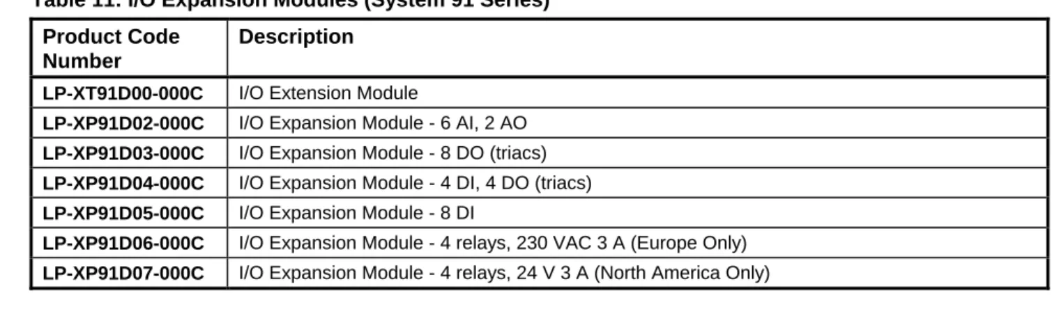
Table 11: I/O Expansion Modules (System 91 Series) Product Code
Number
Description
LP-XT91D00-000C I/O Extension Module
LP-XP91D02-000C I/O Expansion Module - 6 AI, 2 AO LP-XP91D03-000C I/O Expansion Module - 8 DO (triacs) LP-XP91D04-000C I/O Expansion Module - 4 DI, 4 DO (triacs) LP-XP91D05-000C I/O Expansion Module - 8 DI
LP-XP91D06-000C I/O Expansion Module - 4 relays, 230 VAC 3 A (Europe Only) LP-XP91D07-000C I/O Expansion Module - 4 relays, 24 V 3 A (North America Only)
Table 12: Software Tools Ordering Information Product Code
Number
Description
LP-FXTPRO-0 FX Tools Pro CD-ROM (FX Builder, FX CommPro N2, FX CommPro LON, FX CommPro BACnet) – New User
LP-FXTPRO-6 FX Tools Pro CD-ROM (FX Builder, FX CommPro N2, FX CommPro LON, FX CommPro BACnet) – Upgrade
Technical Specifications
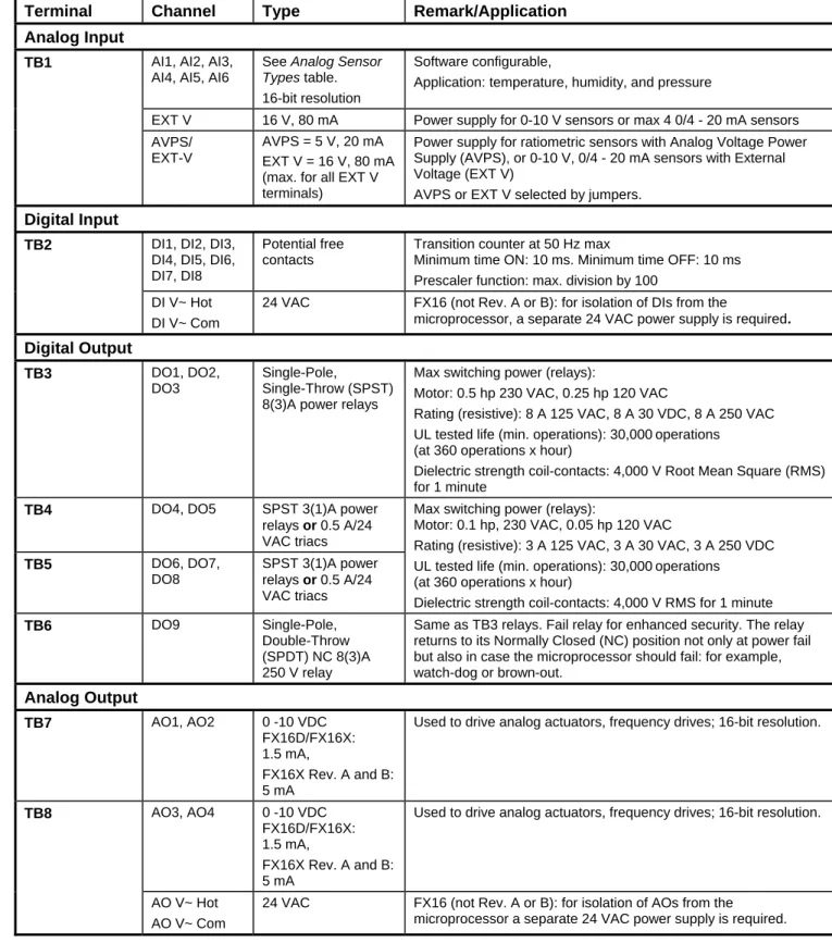
Table 13: I/O DetailsTerminal Channel Type Remark/Application Analog Input
Software configurable, AI1, AI2, AI3,
AI4, AI5, AI6
See Analog Sensor Types
14 FX16 Master Controller Product Bulletin
table. 16-bit resolution
Application: temperature, humidity, and pressure
TB1
EXT V 16 V, 80 mA Power supply for 0-10 V sensors or max 4 0/4 - 20 mA sensors AVPS = 5 V, 20 mA
AVPS/ EXT-V
Power supply for ratiometric sensors with Analog Voltage Power Supply (AVPS), or 0-10 V, 0/4 - 20 mA sensors with External Voltage (EXT V)
EXT V = 16 V, 80 mA (max. for all EXT V
terminals) AVPS or EXT V selected by jumpers.
Digital Input
DI1, DI2, DI3, DI4, DI5, DI6, DI7, DI8
Potential free contacts
Transition counter at 50 Hz max
Minimum time ON: 10 ms. Minimum time OFF: 10 ms Prescaler function: max. division by 100
TB2
DI V~ Hot 24 VAC FX16 (not Rev. A or B): for isolation of DIs from the
microprocessor, a separate 24 VAC power supply is required.
DI V~ Com Digital Output DO1, DO2, DO3 Single-Pole, Single-Throw (SPST) 8(3)A power relays
Max switching power (relays):
TB3
Motor: 0.5 hp 230 VAC, 0.25 hp 120 VAC
Rating (resistive): 8 A 125 VAC, 8 A 30 VDC, 8 A 250 VAC UL tested life (min. operations): 30,000 operations (at 360 operations x hour)
Dielectric strength coil-contacts: 4,000 V Root Mean Square (RMS) for 1 minute
TB4 DO4, DO5 SPST 3(1)A power
relays or 0.5 A/24 VAC triacs
Max switching power (relays):
Motor: 0.1 hp, 230 VAC, 0.05 hp 120 VAC
Rating (resistive): 3 A 125 VAC, 3 A 30 VAC, 3 A 250 VDC DO6, DO7,
DO8
SPST 3(1)A power relays or 0.5 A/24 VAC triacs
TB5 UL tested life (min. operations): 30,000 operations
(at 360 operations x hour)
Dielectric strength coil-contacts: 4,000 V RMS for 1 minute DO9 Single-Pole,
Double-Throw (SPDT) NC 8(3)A 250 V relay
Same as TB3 relays. Fail relay for enhanced security. The relay returns to its Normally Closed (NC) position not only at power fail but also in case the microprocessor should fail: for example, watch-dog or brown-out. TB6 Analog Output AO1, AO2 0 -10 VDC FX16D/FX16X: 1.5 mA,
Used to drive analog actuators, frequency drives; 16-bit resolution.
TB7 FX16X Rev. A and B: 5 mA AO3, AO4 0 -10 VDC FX16D/FX16X: 1.5 mA,
Used to drive analog actuators, frequency drives; 16-bit resolution.
FX16X Rev. A and B: 5 mA
TB8
AO V~ Hot 24 VAC FX16 (not Rev. A or B): for isolation of AOs from the microprocessor a separate 24 VAC power supply is required. AO V~ Com
Table 14: Analog Sensor Types
Sensor Type Linearization Range Accuracy at 20°C (68°F) Ambient -45°C (-49°F) to 120°C (248°F) ±0.5°C (±1°F) Ni 1000 (Johnson Controls) 20°C (68°F) to 287°C (548.6°F) ±0.5°C (±1°F) Ni 1000 (Johnson Controls) Extended Range -50°C (-58°F) to 160°C (320°F) ±0.5°C (±1°F) Ni 1000 Siemens® -60°C (-76°F) to 180°C (356°F) ±0.5°C (±1°F) Ni 1000 DIN
FX16 Master Controller Product Bulletin 15
Pt 1000 -50°C (-58°F) to 160°C (320°F) ±0.5°C (±1°F) -50°C (-58°F) to 100°C (212°F) ±0.5°C (±1°F) A99 -40°C (-40°F) to 150°C (302°F) ±0.5°C (±1°F) NTC 2.25k -40°C (-40°F) to 150°C (302°F) ±0.5°C (±1°F) NTC 10k 10 to 90% of supply voltage (0.5 to 4.5 V nominal) ±0.05 VDC 0 to 5 VDC Ratiometric 0 to 10 V ±0.05 VDC Active 0 to 10 VDC 0 to 20 mA ±0.1 mA Active 0 to 20 mA
Table 15: Master Controller Standard and Extended Range Models
FX16D Master Controller Product
FX16X Master Controller Extended Temperature Range
24 VAC ±15%, 50/60 Hz - Class 2 Power Supply – Safety Extra-Low Voltage (SELV) in Europe
Power Supply Requirements
15 VA at max load Power Consumption 2 A, 250 V Internal Fuse IP 20 CEI/EN60529 Protection Class
Ambient Operating Conditions FX16D: -20 to 50°C (-4 to 122°F),10 to 95% RH (noncondensing)
FX16X Extended Temperature Range: -40 to 60°C (-40 to 140°F),10 to 95% RH (noncondensing) (Integral Display may not operate below -20°C [-4°F])
-40 to 70°C (-40 to 158°F), 10 to 95% RH (noncondensing) Ambient Storage Conditions
Dimensions (H x W x D) 142 (including terminals) x 215 x 49 mm (66 mm with integral display) 5.59 (including terminals) x 8.46 x 1.93 in. (2.6 in. with integral display) 0.95 kg (2.1 lb)
Weight (in package)
Real-Time Clock Accuracy: Better than ± 200 ms per day at constant ambient temperature of 25°C Backup: Minimum 3 years without power at 25°C
2
Screw terminals for max 2 x 1.5 mm (16 AWG) wires Connection Terminals for Inputs,
Outputs, and Power Supply
Screw terminals, cable size 0.5 mm to 1.5 mm2, 24 to 16 AWG, Belden® cable, 4-core twisted pair with shield
N2 Open and BACnet MS/TP Bus Connection Terminals
Screw terminals, cable size 0.5 mm to 1.5 mm2, 24 to 16 AWG, Belden cable, 2-core twisted pair with shield
LON Network Connection Terminals
Screw terminals, cable size 0.5 mm to 1.5 mm2, 24 to 16 AWG, Belden cable, 4-core twisted pair with shield
Connection for Extension Bus and Remote Display
BACnet Testing Laboratories™ (BTL) Listing
BACnet Interoperability Building Blocks (BIBBs): BACnet Advanced Application Controller (B-AAC)
Protocol Implementation Conformance Statement (PICS) available on request BACnet® Compliance
– 89/336/EEC, EMC Directive: EN 61000-6-3, EN 61000-6-1
16 FX16 Master Controller Product Bulletin
Europe
– 72/23/EEC, Low Voltage Directive: EN 60730 CE and UL Compliance
– UL Listed (PAZX7), CAN/CSA C22.2 No. 205, Signal Equipment Canada
– Industry Canada, ICES-003
– UL Listed (PAZX), UL 916, Energy Management Equipment United
States – FCC compliant to CFR 47, Part 15, Subpart B, Class A
The performance specifications are nominal and conform to acceptable industry standards. For application at conditions beyond these specifications, consult the local Johnson Controls office. Johnson Controls, Inc. shall not be liable for damages resulting from misapplication or misuse of its products.
Building Efficiency 507 E. Michigan Street, Milwaukee, WI 53202
Johnson Controls® is a registered trademark of Johnson Controls, Inc. All other marks herein are the marks of their respective owners. © 2008 Johnson Controls, Inc.