Applying NFV and SDN to LTE Mobile Core Gateways;
The Functions Placement Problem
Arsany Basta, Wolfgang Kellerer
Institute for Communication NetworksTechnische Universität München Munich, Germany
arsany.basta, [email protected]
Marco Hoffmann, Hans Jochen Morper,
Klaus Hoffmann
Nokia Solutions and Networks Munich, Germany
marco.hoffmann, hans-jochen.morper,
[email protected]
ABSTRACT
With the rapid growth of user data, service innovation, and the persistent necessity to reduce costs, today’s mobile op-erators are faced with severe challenges. In networking, two new concepts have emerged aiming at cost reduction, in-crease of network scalability and service flexibility, namely Network Functions Virtualization (NFV) and Software De-fined Networking (SDN). NFV proposes to run the mobile network functions as software instances on commodity servers or datacenters, while SDN supports a decomposition of the mobile network into control-plane and data-plane functions. Whereas these new concepts are considered as very promis-ing drivers to design cost efficient mobile network architec-tures, limited attention has been drawn to the network load and infringed data-plane delay imposed by introducing NFV or SDN. We argue that within a widely-spanned mobile net-work, there is in fact a high potential to combine both con-cepts. Taking load and delay into account, there will be areas of the mobile network rather benefiting from an NFV deployment with all functions virtualized, while for other areas, an SDN deployment with functions decomposition is more advantageous. We refer to this problem as the func-tions placement problem. We propose a model that resolves the functions placement and aims at minimizing the trans-port network load overhead against several parameters such as data-plane delay, number and placement of potential dat-acenters and SDN control overhead. We illustrate our pro-posed concept along with a concrete use case example.
Keywords
NFV, SDN, LTE Core Gateways
1.
INTRODUCTION
The mobile cellular network has recently seen a rapid de-velopment, in particular with the introduction of the 4th generation LTE network. Today’s mobile cellular networks are capable of offering higher data rates, integrating more services and guaranteeing a higher quality of experience. However, this development means also that the volume of data to be transported within a mobile network is increas-ing as well. In addition, market competition requires faster service deployment and elasticity in changing the service cri-teria and cope with higher service requirements to keep the maximum user experience. All of these points cause a drastic reduction in the operators revenues and consequently result in a need for Total Cost of Ownership (TCO) reduction, to
be able to keep a revenue margin [1]. Two concepts are in the focus of research and development at the moment.
The Network Functions Virtualization (NFV) [2] concept emerged to virtualize mobile network functions and move them to commodity hardware or datacenter (DC) platform. NFV allows operators to decouple the dependency from spe-cialized equipment and operate network functions as virtu-alized software instances on standardized servers instead.
This deployment concept of virtualized network functions brings several advantages with respect to scalability, better network dimensioning, load optimization or energy savings. The possibility of incremental and scalable functional addi-tions without the need to install or acquire specialized equip-ment is definitely of huge value. In addition, a mobile net-work would become more dynamic as virtualized platforms support a rapid instantiation, tearing down or dynamic allo-cation of resources. Dynamic network instantiation is seen as an important tool to cope with the rapid change of ser-vices and users behavior. Therefore, it is expected that NFV would have an impact on the desired cost reduction in to-day’s mobile networks.
Meanwhile, Software Defined Networking (SDN) [3] has been considered as a complementary deployment concept for mobile networks. SDN introduces what we call Network Functions Decomposition (NFD), where control-plane func-tions would be appended to a logically centralized controller that could be deployed in a datacenter platform, while data-plane functions are realized by SDN networking elements at the transport network.
The advantages of having an SDN-based mobile network architecture include programmability and thus flexibility for the operator to control and manage its network. Such con-trol enables the operator to steer the data traffic on run-time basis and tailor the data flow inside the network. This leads to an increase in the services quality and user experience in addition to the potential of cost savings.
Whereas introducing NFV to the mobile network has lots of advantages as previously mentioned, it also requires trans-porting the whole network data traffic to the operator’s datacenters which imposes additional load on the transport network. Furthermore, an additional data traffic delay is ex-pected which requires a thorough planning of the datacenter location within the mobile network. In the same way, intro-ducing SDN adds an extra control-plane that is not present in the standard architecture, which similarly imposes addi-tional transport network load overhead, depending on the SDN control volume.
In order to investigate this additional overhead, we focus on the two main functions of the LTE mobile core, which involve both control and data-plane functions; the Serving Gateway (SGW) and PDN Gateway (PGW). Our main aim is to investigate the influence of virtualizing or decomposing those two central functions on the transport network load and data-plane delay.
Related Work Introducing functions virtualization and
SDN to the LTE mobile network has been the focus of recent research work, triggered by the NFV initiative and adoption of SDN. There are some studies that are concerned with the architectural aspects of migrating the mobile functions to a datacenter, as in [4] which highlights the advantages and use-cases of virtualized mobile functions. [5] propose the uti-lization of a datacenter platform to offload the mobile core traffic. Regarding SDN, we have presented in [6], an analy-sis of different mobile functions deployment architectures in addition to their realization through SDN. Conceptual ar-chitectures and use-cases of an SDN-based mobile core have been additionally discussed in [7]. While the authors in [8] have concluded to the need for enhanced SDN networking el-ements. [9] proposed the use of middleboxes to provide flex-ibility and policy enforcement in the mobile core via SDN. Nevertheless, it can be seen that early investigations were concerned with the architecture design and most proposals and studies focus on one concept only, either virtualization or SDN.
The objective of this paper is to define, model and solve the problem of applying virtualization, SDN decomposition or a combination of both concepts on the mobile core gate-ways. In other words, for each mobile core gateway, this problem intends to decide whether to virtualize and migrate all gateways functions to a datacenter or decompose this gateway as a controller residing in a datacenter and a net-working element at the transport network, we call this the functions placement problem. It also addresses the opti-mal placement of the datacenters, which host the virtual-ized gateways as well the SDN controllers. The controllers placement problem has been previously addressed in [10] and [11] but with a main focus on achieving minimum SDN control delay as well as resilience provisioning. In our study, the optimal functions placement aims at minimizing the net-work load and satisfying the data-plane delay budget as well. Note that this novel problem could also be adapted to other network functions.
2.
MOBILE CORE GATEWAYS RE-DESIGN
In this section, we discuss the functions allocation for both virtualized or SDN decomposed deployments in addition to the required transport network elements. In our previous work [6], we have presented a thorough analysis and clas-sification of the main SGW and PGW functions. We have grouped the classified functions into two main categories as follows: (1) Control-plane functions, as for example LTE signaling or resources allocation (2) Data-plane functions, required for both SGW and PGW such as GTP Tunneling, or additional functions needed at the PGW only such as QoS enforcement or charging.
2.1
Virtualized Gateway
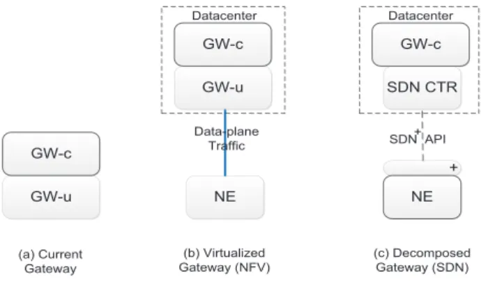
Applying the concept of NFV to the current gateway ar-chitecture shown in Figure 1(a) results in moving the control-plane (GW-c) and data-control-plane (GW-u) functions to an
oper-GW-u GW-c + NE NE SDN CTR (a) Current Gateway (b) Virtualized Gateway (NFV) (c) Decomposed Gateway (SDN) SDN API Datacenter Datacenter Data-plane Traffic + GW-u GW-c GW-c S
Figure 1: Mobile Core Gateways Re-design
ator’s datacenter as shown in Figure 1(b). In this case, an off-the-shelf network element (NE) would be used to direct the data traffic from the transport network to the intended datacenter. All further processing would be done by the virtualized gateway instance. Note that the network ele-ment could be either a typical transport switching eleele-ment or otherwise a standard SDN network element, in case flex-ible data flow handling between the transport network and datacenters is desired and beneficial for the operator.
2.2
SDN Decomposed Gateway
An SDN decomposed gateway is illustrated in Figure 1(c), SDN controllers are extended with control-plane gateway functions as for example LTE signaling, and hosted within operator deployed datacenters. In this case, enhanced SDN network elements are needed which we call ”SDN NE+”, where the ”+” resembles the previously mentioned data-plane gateway functions such as GTP tunneling or charg-ing which cannot be realized with current SDN network el-ements. In addition, an extended SDN API that should be adopted by the operator to program and control those fea-tures. In this case, the data traffic is kept at the transport network while only SDN control is flowing between the dat-acenter and the transport NE+.
3.
PROCESSING DELAY MEASUREMENT
The data-plane traffic delay within the mobile core, i.e. traffic forwarded through the gateways between the access network and IP domains, could be simply defined as the sum of packet propagation delayTpropon each link in addition to
the packet processing delayTprocat each node a packet
tra-verses. The propagation delays depend on the link distances and transport technology between the gateways which we cover in our model in Section 4. In this section we aim at providing a quantitative comparison between the fully vir-tualized and SDN decomposed gateways by measuring the data-plane packet processing delays.
For our measurement, the first step was to develop proto-type implementations, abstracted versions from the 3GPP standard, of the previously classified SGW and PGW tions, most importantly the GTP packet processing func-tion. For the virtualized gateway, we have developed a GTP packet processor in java. The virtualized gateway has been hosted on one of our server nodes and was allocated 20 In-tel(R) Xeon(R) CPU E5-2690 v2 @ 3.00GHz virtual CPU core with 128 GB RAM.
Table 1: Mean Packet Processing Delay no. of Tunnels 10 100 1 K 10 K bits/sec 1 M 10 M 100 M 1 G packets/sec 83 830 8.3 K 83 K Virtualized GWTproc 62µs 83µs 109µs 132µs Decomposed GWTproc 15µs 15µs 15µs 15µs
Regarding the SDN decomposed gateway evaluation, the SDN NE+ has been realized using an NEC PF5420 Open-Flow switch from our SDN testbed, running OF 1.3 firmware [12] and supporting a rate of 1 Gbps per physical port. It should be noted that since GTP headers are not included in the OF match fields specification, we have emulated the NE+ packet processing as header bits modification using OF Modify action. Additionally, the open source java floodlight controller [13] has been modified and extended to represent the gateway’s control-plane.
Our measurement setup consisted of a measurement PC with a 4 ports DAG card which has a time stamping preci-sion innsec. Network taps were used to capture the traffic and forward duplicate copies to the measurement PC which then calculates the packet processing delay. The taps were directly connected within a small vicinity to the SDN switch and the server node running the software packet processor, to eliminate any propagation delay.
The packet processing delay, of both the virtualized soft-ware function and SDN networking element, has been mea-sured against different values of data rate, number of packets per second and number of established tunnels. Each mea-surement run lasted for a duration of 10 seconds. The mean delay is calculated for each run, where the overall mean, shown in Table 1, is calculated within 95% confidence and at least 100 runs. A fixed packet size was considered of 1500 Bytes. Note that the SDN signaling or tunnel establish-ment delay is not considered in this case as the main focus is packet processing delays. Hence, delay measurements are triggered after all tunnels are established.
The decomposed gateway, emulated by an SDN switch, shows a stable processing delay of 15µsecs over the range of parameters. It can be seen that the virtualized gate-way, running in software, experiences higher processing de-lays compared to the decomposed gateway with a maximum of 132µsecsin case of 1 Gbps line rate. This is in line with common observations in switch design where packet process-ing in hardware is typically faster than software processprocess-ing, certainly dependent on the available resources.
4.
MODEL FORMULATION
In this section, we formulate a model that evaluates the different gateway deployments in a mobile core network, where the aforementioned processing delay measurements are input parameters. As previously discussed in Section 2, considering the core gateway as a network function, it could be either virtualized and moved to a datacenter where the gateway is replaced with a switching NE which steers the traffic towards the datacenter. Alternatively, a gateway function could be decomposed between an enhanced SDN NE+ and an extended controller which is hosted by a dat-acenter. In our study, we target a first step migration sce-nario, so we keep the gateways’ geographical locations un-changed. Additionally, we assume that datacenters would be placed in a location where the operator has already an
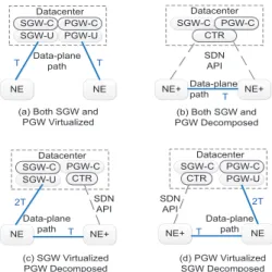
SGW-U PGW-C Datacenter SGW-C SGW-U PGW-U Datacenter
(a) Both SGW and PGW Virtualized Data-plane path NE NE D NE+ NE+ SGW-C PGW-C Datacenter SDN API NE NE+ SGW-C PGW-C SDN API PGW-U PGW-C Datacenter SGW-C NE+ NE SDN API (b) Both SGW and PGW Decomposed (c) SGW Virtualized PGW Decomposed (d) PGW Virtualized SGW Decomposed Data-plane path Data-plane path Data-plane path T T 2T T T 2T T CTR CTR CTR
Figure 2: Alternative Paths for Data-plane Demand between SGW and PGW, Demand = T
existing site to reduce the floor space cost i.e the datacenter is placed in a location where an operator has a gateway.
The problem is formulated as a path-flow model consider-ing transport data-plane demands between SGWs and PGWs. For each demand, there are four possible paths depending on the SGW and PGW functions placement shown in Fig-ure 2 and considering the datacenter location. Hence, for each traffic demand, the selected path results in the SGW and PGW functions placement and datacenter location. De-mands are considered to be uniform, bi-directional and non-splittable. We define the total load as the sum of the data-plane traffic or SDN control traffic on each link multiplied by its length, over all links. The problem’s objective is to determine each gateway function placement and datacenter location, which minimizes the total transport network load, as follows: min∑ c∈C ∑ d∈D ∑ p∈P δc,p,dNc,p,d (1)
where the set C includes all possible locations of the K datacenters. δc,p,d is a binary variable which denotes that
a pathp is chosen for demandd, with the location of dat-acenter c. The parameter Nc,p,d is pcalculated load
re-sulted from a combination of datacenter location, path and demand. The constraints are given by:
∑ c∈C δc=K (2) ∑ p∈P δc,p,d≤δc ∀d∈D, c∈C (3) ∑ c∈C ∑ p∈P δc,p,d= 1 ∀d∈D (4) ∑ p∈P δc,p,dLc,p,d≤Lbudget ∀d∈D, c∈C (5)
where (2) ensures that K datacenters are chosen. (3) reflects that if a datacentercis chosen, a pathpfor demanddcould be chosen using this datacenter c. In case of K selected datacenters, only one path using one datacenter for each de-mand is chosen, guaranteed by (4). Finally, (5) ensures that the chosen path satisfies the data-plane delay budget where parameter Lc,p,d is pre-calculated latency resulted from a
S S S S S S S S S P P P P S S S S S S S S S Cluster 1 Cluster 2 Cluster3 Cluster 4 SGW PGW
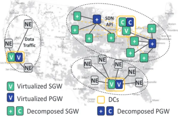
Figure 3: Presumed Core Gateways Topology based on LTE Coverage Map in [15]
5.
SIMULATION AND EVALUATION
For simulation, a java framework was developed and we used Gurobi [14] as the optimization problem solver. It is known that it is quite difficult to set hands on a real de-ployment topology of an operator’s mobile core. Therefore, we presumed a core gateways topology for the US as shown in Figure 3, based on LTE coverage map in [15]. The The topology consists of 4 clusters with 4 PGWs and 18 SGWs in total. The gateways are assumed to be fully meshed i.e. a link could be established from any gateway to any other.
The data-plane delay budget is defined for the different SGW-PGW interface realizations, either going through the datacenter or between NE+ equipment. Each datacenter hosts the virtualized gateways and the control functions of decomposed gateways i.e extended SDN controller, respec-tively. The processing delay input is taken from our previous measurement as an average of 10µsec for the decomposed gateway transport element (NE+) and 100µsecfor the vir-tualized gateway transport element (NE). An underlying op-tical transport network has been considered which results in propagation delays depending on the distances between the functions’ location. So far, constraints on the datacenter available resources or possible alternative locations are not considered. However, these are important factors that we would consider for future work.
There are two sources of traffic that comprise the network load depending on the functions placement. First is the data traffic to be transported between the SGW and PGW. Second, SDN control traffic that is added in case of decom-posed deployment. This SDN control volume is pretty much dependent on the protocol adopted by the operator and the customization added to implement the mobile core functions as for example tunneling or charging. The SDN control vol-ume depends on the LTE signaling that an operator sees within its core network as well. Hence, we have investigated the impact of having different SDN control profiles and we denote it as a percentage of the data volume transported for each gateway. For example, an SDN control profile of 10 % means SDN loads the link from the datacenter to the gate-way by a volume that is one tenth the data volume trans-ported by such gateway. It would be the task of the operator to identify the SDN control volume in its network.
The optimization problem is a deterministic problem, there-fore multiple runs are not needed. The network loadNc,p,d
and path latencyLc,p,d were pre-calculated for all possible
S S S S S S S S S S S S S S S S S S P P P 4 DCs 3 DCs 2 DCs 1 DC P 4, 3, 2 DCs 4 DCs 2 DCs 4,3 DCs 4 DCs 3 DCs
Figure 4: Datacenters Location at K = 4, 3, 2, 1
NE + + NE NE NE NE + + NE NE NE NE V Data Traffic + DCs + + + V + + V V V V C C SDN API V + Virtualized SGW Decomposed SGW C Virtualized PGW + C Decomposed PGW
Figure 5: Functions Placement at 3 Datacenters with SDN Control Volume of 10 % under 5.3 msec
Delay Budget
combinations of datacenter, path and demand, which de-creases the complexity and makes the run time quite fast i.e. in the resolution ofmsecsper iteration.
5.1
Full Virtualized Deployment
The maximum propagation delay between an SGW and its respective PGW in the presumed core topology is 5.128
msec(Figure 3, in cluster 4 between Idaho and Los Angeles) and considering an additional processing delay of 100µsec, the data-plane delay budget has been set to 5.3msec. First question; how many datacenters are needed to fully virtual-ize all gateways and move them to datacenters for this given topology under the 5.3msecdata-plane delay budget?
Figure 4 shows that at least 4 datacenters are needed to support a full migration to virtualized gateways under a data-plane delay budget of 5.3 msec, where a datacenter is located at the PGW of each cluster. The total network load of the original presumed gateway topology has been calculated to be used as a reference for the load overhead. In this case, the total network load with 4 datacenters is equal to the total network load in the original presumed gateway topology. In such tree structure at each cluster, placing the gateway functions at the tree root node would diminish any extra traffic transport overhead. It has also been noted that with a fewer number of datacenters, it is infeasible to fully virtualize all gateways under such data-plane delay constraint.
(a) Network Load
(b) Transport Network Elements
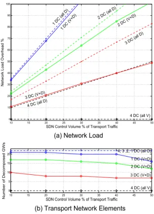
4 DC (all D) 3 DC (V+ D) 2 DC (V+D ) 3 DC (all D ) 2 DC (all D ) 1 D C (a ll D ) 1 D C (V +D) 4 DC (all V) 3 DC (V+D) 2 DC (V+D) 1 DC (V+D) 10 15 20 25 30 35 40 45 50 0 10 20 30 40 50 60 70 80 90 100
SDN Control Volume % of Transport Traffic
N e tw o rk L o a d O ve rh e a d % 4 DC (all V) 10 15 20 25 30 35 40 45 50 0 5 10 15 20
SDN Control Volume % of Transport Traffic
N u mb e r o f D e co mp o se d G W s 4, 3 ,2, 1 DC (all D)
Figure 6: 5 ms Data-plane Delay Budget
5.2
Virtualized and Decomposed Deployments
Combination
Another conclusion that can be drawn from the above re-sults is that, if we want to operate less than four datacenters in this given topology and under a strict delay budget, de-composed gateways are needed to keep a subset of the data traffic at the transport network . Hence, we solve again our functions placement problem with the possibility of having virtualized or decomposed gateways, which minimizes the total network load under the same data-plane delay bud-get of 5.3msec. The resulting datacenter placement with the respective network partitioning is illustrated in Figure 4, ranging from 3 to 1 available datacenters. A snapshot of the functions placement with a combined virtualized and decom-posed deployment is shown in Figure 5, using 3 datacenters and SDN control volume of 10 % under 5.3msecdelay bud-get. We also solve the problem for a full decomposed gate-way deployment, i.e. all gategate-ways are decomposed, to have a comparison with the combined virtualized and decomposed gateway deployment. The total network load of the original core topology has been calculated to be used as a reference for the load overhead.
5.2.1
Network Load Overhead
It is shown in Figure 6(a) that the number of datacenters represents an important factor in determining the network load overhead as the total network load increases signifi-cantly in case fewer datacenters are deployed. For instance, at a 10% SDN control volume, the combined virtualized and decomposed gateways deployment with 3, 2 and 1 datacen-ters show 11%, 21% and 34% load overhead, respectively. A single datacenter is showing a significant load overhead with
(b) Transport Network Elements
4 DC (all D) 3 DC (V+ D) 2 DC (V+D ) 3 DC (all D ) 2 DC (all D ) 1 D C (a ll D ) 1 D C (V +D ) 10 15 20 25 30 35 40 45 50 0 10 20 30 40 50 60 70 80 90 100
SDN Control Volume % of Transport Traffic
N e tw o rk L o a d O ve rh e a d % 4 DC (all V)
(a) Network Load
10 15 20 25 30 35 40 45 50 0 5 10 15 20
SDN Control Volume % of Transport Traffic
N u mb e r o f D e co m p o s e d G W s 4 DC (all V) 3 DC (V+D) 2 DC (V+D) 1 DC (V+D) 4, 3 ,2, 1 DC (all D)
Figure 7: 10 ms Data-plane Delay Budget
a steeper incline as the SDN control volume increases, dou-bling the traffic inside the core network at an SDN control volume of 29%. This is due to the extra SDN control-plane and the high number of NE+ needed shown at Figure 6(b) for a single datacenter.
Figure 6(a) shows also that with the considered topol-ogy and input parameters, a combined virtualized and de-composed gateway deployment outperforms the deployment with only decomposed gateways in all cases of K datacen-ters, concerning network load overhead. Furthermore, the load overhead resulted by a combined deployment using 3 datacenters approaches the full decomposed gateways de-ployment using 4 datacenters.
Additionally, the network load overhead gap observed be-tween the combined deployment and the full decomposed deployment is seen to be closing down as the number of available datacenters decreases. This could be explained by Figure 6(b) which shows that the number of needed de-composed gateways is increasing while fewer datacenters are used, approaching a full decomposed deployment. In case of a single datacenter, 21 out of 22 gateways are decomposed.
5.2.2
Functions Placement
Figure 6(b) shows that the number of decomposed gate-ways, realized by SDN NE+ at the transport network, in-creases significantly with the availability of fewer datacen-ters. This is to avoid the extra delays of transporting the traffic through the datacenter under such data-plane delay budget of 5.3msec. For instance at an SDN control volume of 10%, if an operator decides to deploy a combination of virtualized and decomposed gateways using 3 datacenters instead of a full virtualized deployment with 4 datacenters,
45% of the transport network elements are required to be decomposed gateways or enhanced SDN NE+. In this case, a cost analysis is essential for the operator to evaluate the cost difference between the deployment of a datacenter or deploying enhanced transport network elements.
Regarding datacenters placement, it is observed that each datacenter is placed in a central location towards the respec-tive transport network elements within its selected network partition, as in the case of 3 datacenters and SDN control volume of 10 %, shown in Figure 5. The centrality of each datacenter in its respective network partition is an indication for the transport network load balancing and the responsive-ness of the SDN control as well.
5.3
Delay Budget Relaxation
In the previous subsection, the gateway functions have been placed under a strict data-plane delay budget of 5.3msec. We solve the problem again yet after relaxing the data-plane delay budget to 10msec to observe the impact of relaxing the data-plane delay constraint on particularly the functions placement and total network load. Note that higher delay budgets could be tolerated by some services, yet nowadays mobile networks attempt to offer less delays to improve the user satisfaction.
For a full virtualized gateways deployment, it is still infea-sible with fewer than 4 datacenters, which again points out to the necessity of a combined virtualized and decomposed deployment for the case of using less than 4 datacenters.
The network load overhead after relaxing the delay-budget to 10msec is quite comparable to 5.3msec, shown in Fig-ure 7(a). However, with a higher data-plane delay toler-ated, it is affordable to deploy more virtualized gateways in case the SDN control volume increases, to keep a minimum network load, as illustrated in Figure 7(b).
6.
CONCLUSION
In this paper, we discuss alternative deployments for mo-bile core network gateways, namely fully virtualized gate-ways hosted in a datacenter and decomposed gategate-ways based on SDN. We analyze possible placements of virtualized gate-ways or decomposed gateway functions with respect to delay and imposed network load. We call this the network func-tions placement problem. As a basis, we provide a packet processing delay measurement for our virtualized and de-composed gateway implementation. For fully virtualized gateways, the processing delay results in a maximum of 132µscompared to 15µsin case of decomposed gateways.
As a solution to the functions placement problem, we pro-vide a model that minimizes the network load, comprised of transport data-plane in addition to SDN control if decom-posed gateways are present, for a certain data-plane delay budget. We consider the proposed model to be a solid tool for mobile operators to plan the migration of mobile core gateways to NFV or SDN.
For an exemplary gateway deployment in a US network, the problem has been solved against different number of available datacenters, delay-budgets and SDN control vol-ume. In this setting, four datacenters are required to sup-port a full virtualized gateways deployment. If less than four datacenters are available, a combined deployment of fully virtualized gateways and decomposed gateway func-tions is most suitable with respect to network load overhead and delay constraints.
Outlook For future work, further constraints to the
func-tions placement problem could be included, which consider the available resources at each datacenter or the transport network links available bandwidth. Additionally, non-uniform traffic patterns in the mobile core could be adopted, which are based for example on user population density. The for-mulated problem could also be extended to incorporate other mobile network functions.
7.
REFERENCES
[1] Nokia Solutions and Networks. Enabling Mobile Broadband Growth, white paper. December 2013.
https://nsn.com/system/files/document/epc_ white_paper.pdf.
[2] SDN and OpenFlow World Congress. Network Function Virtualization, update white paper. October 2013.https:
//portal.etsi.org/NFV/NFV_White_Paper2.pdf. [3] ONF. Software-Defined Networking: The New Norm
for Networks, white paper. April 2012.
https://www.opennetworking.org/downloads/ sdn-resources/white-papers/wp-sdn-newnorm.pdf. [4] Nokia Solutions and Networks. Technology Vision for
the Gigabit Experience, white paper. June 2013.
https://nsn.com/file/26156/
nsn-technology-vision-2020-white-paper.pdf. [5] Arijit Banerjee and Xu Chen. MOCA: a lightweight
mobile cloud offloading architecture.ACM MobiArch, 2013.
[6] Arsany Basta, Wolfgang Kellerer, Marco Hoffmann, Klaus Hoffmann, and Ernst-Dieter Schmidt. A Virtual SDN-Enabled LTE EPC Architecture: A Case Study for S-/P-Gateways Functions.IEEE SDN4FNS, 2013. [7] Georg Hampel, Moritz Steiner, and Tian Bu.
Applying software-defined networking to the telecom domain.Computer Communications Workshops (INFOCOM WKSHPS), 2013.
[8] James Kempf and Bengt Johansson. Moving the mobile evolved packet core to the cloud.IEEE WiMob, 2012.
[9] Xin Jin, Li Erran Li, Laurent Vanbever, and Jennifer Rexford. SoftCell: scalable and flexible cellular core network architecture.ACM CoNEXT, 2013.
[10] Brandon Heller, Rob Sherwood, and Nick McKeown. The controller placement problem.ACM HotSDN, 2012.
[11] David Hock, Matthias Hartmann, Steffen Gebert, Michael Jarschel, Thomas Zinner, and Phuoc Tran-Gia. Pareto-optimal resilient controller placement in SDN-based core networks.ITC, 2013. [12] ONF. OpenFlow Switch Specification Version 1.3.0.
2012.https://www.opennetworking.org/downloads/ sdn-resources/onf-specifications/openflow/ openflow-spec-v1.3.0.pdf.
[13] Floodlight OpenFlow Conroller.
http://www.projectfloodlight.org/floodlight. [14] Gurobi Optimizer.http:
//www.gurobi.com/products/gurobi-optimizer/. [15] LTE Coverage Map.
http://www.mosaik.com/marketing/cellmaps/ ;http://platform.cellmaps.com/.