Cache Conscious Data Layouting
for In-Memory Databases
A Thesis submitted for the degree of Diplom Informatiker
at the Institute of Computer Science/Humboldt-Universit¨at zu Berlin
Holger Pirk
<pirk@informatik.hu-berlin.de>
Matrikelnummer: 195155
Gutachter:
Professor Doktor Ulf Leser, Humboldt-Universit¨
at zu Berlin
Doktor Alexander Zeier, Hasso Plattner-Institut f¨
ur Softwaresystemtechnik
Betreuer:
Martin Grund, Hasso Plattner-Institut f¨
ur Softwaresystemtechnik
Abstract
Many applications with manually implemented data management exhibit a data storage pattern in which semantically related data items are stored closer in mem-ory than unrelated data items. The strong sematic relationship between these data items commonly induces contemporary accesses to them. This is called the princi-ple of data locality and has been recognized by hardware vendors. It is commonly exploited to improve the performance of hardware. General Purpose Database Man-agement Systems (DBMSs), whose main goal is to simplify optimal data storage and processing, generally fall short of this claim because the usage pattern of the stored data cannot be anticipated when designing the system. The current interest in column oriented databases indicates that one strategy does not fit all applications. A DBMS that automatically adapts it’s storage strategy to the workload of the database promises a significant performance increase by maximizing the benefit of hardware optimizations that are based on the principle of data locality.
This thesis gives an overview of optimizations that are based on the principle of data locality and the effect they have on the data access performance of applications. Based on the findings, a model is introduced that allows an estimation of the costs of data accesses based on the arrangement of the data in the main memory. This model is evaluated through a series of experiments and incorporated into an automatic layouting component for a DBMS. This layouting component allows the calculation of an analytically optimal storage layout. The performance benefits brought by this componentt are evaluated in an application benchmark.
Zusammenfassung
Viele Anwendungen mit selbst implementierter Datenhaltung zeigen ein
Spe-icherverhalten bei dem semantisch zusammenh¨angende Daten im Speicher n¨aher
beieinander gespeichert werden als semantisch unzusammenh¨angende Daten. Der
starke semantische Zusammenhang zwischen diesen Daten f¨uhrt zu h¨aufigen
zeitna-hen Zugriffen auf sie. Dieses Prinzip, das Prinzip von semantischer Datenlokalit¨at,
wurde von Hardwareherstellern erkannt und ist die Basis f¨ur viele
Verbesserun-gen der Hardware die die Ausf¨uhrungsgeschwindigkeit der Software steigern. Nicht
spezialisierte Datenbank Management Systeme (DBMSe), deren Ziel die Verein-fachung einer optimalen Datenspeicherung und -verarbeitung ist, verfehlen dieses Ziel oft weil das Nutzungsmuster der gespeicherten Daten beim Entwickeln des Systems nicht bekannt ist und daher nicht zur optimierung genutzt werden kann. Das aktuelle interesse an spaltenorientierten Datenbanksystemen macht deutlich das eine Strategie nicht f¨ur alle F¨alle geeignet ist. Ein Datenbanksystem dass seine Speicherstrategie dem Nutzungsmuster der Datenbank anpasst kann deutliche Leis-tungssteigerungen erzielen, da es die Optimierungen der Hardware am besten aus-nutzen kann.
Diese Diplomarbeit soll einen ¨Uberblick ¨uber die Optimierungen geben, die
auf dem Prinzip der semantischen Datenlokalit¨at basieren. Ihr Effekt auf die
Ausf¨uhrungsgeschwindigkeit soll untersucht werden. Aufbauend auf den
resultieren-den Erkenntnissen soll ein Modell eingef¨uhrt werden dass eine Absch¨atzung der
Datenzugriffskosten in Abh¨angigkeit der Anordnung der Daten im Speicher erlaubt.
Dieses Modell wird durch eine Reihe von Experimenten evaluiert und anschliessend in eine Komponente zur Anordnung der Daten eines DBMSs eingearbeitet werden. Diese Komponente erlaubt die Berechnung einer analytisch optimalen Anordnung der Daten im Speicher. Theorie, Umsetzung und Leistungssteigerungen durch diese Optimierung werden beschrieben.
Acknowledgements
I want to thank Prof. Dr. Hasso Plattner and Dr. Alexander Zeier for giving me the possibility to work on this thesis. My mentors for this thesis, Prof. Dr. Ulf
Leser, Martin Grund and Jens Kr¨uger provided valuable feedback for which I am
grateful. My father, Thomas Pirk, helped me by providing valuable insights into
1980’s hardware. This thesis would not have been possible without Anja Pr¨ufert.
She took care of our daughter when I was busy writing and listened to my half finished ideas when I needed to talk things through.
Selbstst¨
andigkeitserkl¨
arung
Hiermit erkl¨are ich, dass ich die vorliegende Arbeit selbstst¨andig und nur unter Verwendung der angegebe-nen Quellen und Hilfsmittel angefertigt habe.
Potsdam, den 17. Januar 2010
Einverstandniserkl¨
arung
Hiermit erkl¨are ich mein Einverst¨andnis, dass die vorliegende Arbeit in der Bibliothek des Instituts f¨ur
Informatik der Humboldt-Universit¨at zu Berlin ausgestellt werden darf.
Contents
1 Introduction 8
1.1 Motivation . . . 8
1.2 Problem Statement . . . 11
1.3 Structure of This Work . . . 11
2 Background on Database Storage Performance 12 2.1 Disk-Based Data Access Performance . . . 12
2.2 A Primer on Main Memory Data Access . . . 13
2.2.1 The Myth of Random Access . . . 13
2.2.2 Determining Factors for Data Access Performance . . . 15
2.2.3 Caches in Current CPUs . . . 17
2.2.4 Blocks in the Memory Modules . . . 21
2.3 Data Access Performance of Different Database Management Systems . . . 22
2.3.1 In-Memory Database Management Systems . . . 22
3 Data Layouting based on Estimated Query Costs 25 3.1 Query Cost Estimation . . . 25
3.1.1 Relational Algebra . . . 25
3.1.2 Query Cost Estimation . . . 26
3.1.3 The Generic Cost Model . . . 28
3.1.4 Extensions to the Generic Cost Model . . . 36
3.1.5 Modeling the Query Processor . . . 39
3.2 Data Layouting . . . 42
3.2.1 Formal Problem Definition . . . 42
3.2.2 Independence of Relation Orientation . . . 43
3.2.3 Unpartitioned Layouting . . . 44
3.2.4 Vertically Partitioned Layouting . . . 45
4 Implementation of Spades - an Automatic Data Layouter 48 4.1 Requirements . . . 48
4.2 The SQL Compiler . . . 49
4.2.1 Existing Compilers . . . 49
4.2.2 Spades’ SQL Compiler . . . 49
4.3 The Cost Calculator . . . 51
4.3.1 Constructing the Cost Function . . . 51
4.3.2 Evaluation of the Cost Function . . . 52
4.4 The Layouter . . . 55
4.4.1 The Simplex Layouter . . . 55
4.4.2 The Partitioned Layouter . . . 55
CONTENTS
5 Evaluation 59
5.1 Performance Counters . . . 59
5.2 Cost Model Evaluation . . . 60
5.2.1 Calibration of the Model . . . 60
5.2.2 Evaluation of the Model . . . 62
5.3 Optimization Performance . . . 66
5.3.1 Benchmark Definition . . . 66
5.3.2 Experiments . . . 67
6 Conclusion and Future Work 72 6.1 Conclusion . . . 72
6.2 Future Work . . . 73
A Sourcecode for Experiments 74 A.1 increasingstride.cpp . . . 74
A.2 increasinguniqueitems.cpp . . . 75
A.3 hash build.cpp . . . 75
A.4 hash probe.cpp . . . 77
A.5 selection with varying selectivity.cpp . . . 78
B Sourcecode of the Spades Implementation 82 B.1 parser.ypp . . . 82
B.2 lexer.lpp . . . 83
B.3 Relational Algebra Data Model . . . 86
B.4 Benchmark Schema . . . 87
List of Figures
1.1 Memory Accesses for different Sample Queries on different Layouts . . . 10
2.1 Costs of a Data Access with varying stride . . . 14
2.2 Costs of a Data Access to an Area of Varying Size . . . 15
2.3 Schema of the Relevant Hardware for In-Memory DBMS . . . 16
2.4 Address Translation of a 32 Bit Address in the Intel Core Architecture (taken from [1]) . 18 2.5 Activities on the Different Memory Layers when Processing Values without Prefetching . 19 2.6 The Effect of Correct Prefetching . . . 20
2.7 The Effect of Incorrect Prefetching . . . 21
3.1 An Example of a Relational Operator-Tree . . . 25
3.2 s trav: Single Sequential Traversal, figure taken from [2] . . . 28
3.3 r trav: Single Random Traversal, figure taken from [2] . . . 28
3.4 rr acc: Repetative Random Access . . . 29
3.5 Additional Miss for Suboptimally aligned Data . . . 31
3.6 Manegolds Equation for distinct record access (top left), Cardenas’ Approximation (top right) and their deviation (bottom) for the first 500x500 Values . . . 33
3.7 A Very Simple Query and It’s Access Patterns . . . 37
3.8 Random vs. Sequential Misses for s trav cr . . . 38
3.9 The search tree for OBP . . . 46
3.10 A case for extended reasonable cuts . . . 47
4.1 The Architecture of Spades . . . 48
4.2 An Example of a Relational Operator-Tree before optimization . . . 51
4.3 The UML diagram of the classes modeling the cache hierarchy and it’s state . . . 52
4.4 The UML Diagram of the Classes Related to the Cost Function . . . 53
5.1 Prediction and measured values for the increasing stride experiment . . . 62
5.2 Costs of a Data Access to an Area of Varying Size . . . 63
5.3 Costs of Hash Building (Parallel Sequential and Random Traversal) . . . 64
5.4 Costs of Hash Probing (Parallel Sequential and Random Traversal) . . . 65
5.5 Costs of a Sequential Traversal Conditional Read . . . 66
5.6 Simulated and Measured Costs of different Layouts . . . 69
List of Tables
3.1 Relational Operators and Their Access Patterns . . . 40
5.1 Memory Access Parameters of the Test System . . . 63
5.2 The Tables used in the benchmark . . . 68
5.3 Queries of the modified SAP SD Benchmark . . . 68
5.4 The layouts generated by Spades . . . 70
5.5 Simulated Costs . . . 71
List of Listings
1 Sample Schema Input . . . 50
2 Pseudocode of the SQL Compiler . . . 50
3 Simplex Algorithm to Calculate the Optial Unpartitioned Layout . . . 56
4 Pseudocode to calculate the Extended Transactions . . . 56
5 Calculating the Possible Oriented Partitionings for a Partitioning . . . 57
6 Oriented Optimal Binary Partitioning in Pseudocode . . . 58
7 Output of the Calibrator . . . 60
Chapter 1
Introduction
1.1
Motivation
Recent developments in Database Management Systems (DBMS) have produced an interesting new concept: column oriented DBMS (column-stores or CStores) [3]. In contrast to the traditional record-wise storage of row oriented DBMS (row-stores) [4] data is stored attribute-record-wise. This improves the performance of queries that operate on many tuples but few attributes, most notably analytical (OLAP) queries. Column oriented DBMS are seen as a strong competitor to classical warehouses that preaggregate data to support performant analytics [5, 6]. Transactional (OLTP) performance, however, is diminished by column-based storage because transactional queries usually operate on many attributes but few tuples. In column oriented storage, These have to be reconstructed from the values of their attributes which takes time [7].
The sacrifice of transactional performance for analytical performance is feasible if one usage pattern outweighs the other by far. Since most businesses have transactional as well as analytical needs, it is common practice to have dedicated, redundant systems with different schemas for each.
Redundant DBMS
Redundant copies of transactional data can be stored in two forms: preaggregated in a data warehouse or in the unaggregated form, but in a specialized analytical DBMS, e.g., a column-store.
A common representative of the redundant storage approach is the following setup [8]: a row oriented transactional DBMS for the OLTP-load and a Data Warehouse for the analytical needs. New data
enters the operational system as it occurs and is loaded into the Warehouse in intervals using anExtract,
Transform and Load (ETL)process [9]. This, however, has several drawbacks:
1. The data that has not been transferred to the OLAP-store yet will not appear in the aggregated results, which renders the OLAP-store constantly out of date [10].
2. All data has to be held twice which increases the costs for hardware acquisition and maintenance [9]. 3. The update process has to be maintained and run periodically to keep the OLAP-store reasonably up to date. Since this process can be complicated, the added costs in hardware and personal can be high [9].
The costs may increase even further with the complexity of the user’s requirements. A common require-ment that is especially interesting isreal-time reporting, i.e. reporting on data that has just entered the
transactional system. Established vendors support real-time reporting, e.g., through means of Active
1.1. MOTIVATION
Active Warehousing
To increase the efficiency of business operations it is often required to do analytics on a relatively short
period of time (an hour or even minutes). This kind ofOperational Reporting[11] is a trend that has been
recognized by vendors [12]. They aim at supporting it by means ofActive Warehousing: The shortening
of the update interval. This reduces the deviance of the aggregates from the real, transactional data and therefore allows almost real time reporting. It does however increase the load on both, the transactional and the analytical database. The transactional database has to handle additional extracts which cannot, as it is common in traditional warehousing, be scheduled in the downtime of transactional operations but have to be executed concurrently to the transactional load.
Lazy Aggregates
The update interval in Active Warehouses is shorter than in traditional warehouses but still a constant. The deviance between the real data is therefore undetermined because it may be changed arbitrarily by a transaction unless special restrictions are implemented. A possibility to limit this deviance is provided by
a technique known asLazy Aggregates [13]. The warehouse update is not triggered after a given interval
but when the deviance exceeds a predefined threshold. This assumes that it is significantly faster to calculate the deviance that is induced by a processed transaction than to run the update. Depending on the aggregation function calculating the deviance without calculating the value can be costly or oven impossible (e.g., for holistic functions). In that case this approach fails to yield any benefit.
Fractured Mirrors
Fractured Mirrors [14] is a technique that can be regarded as a special case of both, Active Warehousing and Lazy Aggregates. The update interval and the accepted threshold are set to zero. This means that every modifying transaction is instantly reflected in the analytical database. Ramamurthy et al. [14] introduced and evaluated the concept for a column-store and a row-store operating in parallel. Each reading query is answered by the most appropriate database, each writing query executed on both. Like all other redundant storage schemes this introduces additional load, hardware and administration costs. The fact that updates/inserts may take a different time in each database further increases the programmatic complexity.
Hybrid DBMS
Both problems, the additional costs as well as the delayed updates, originate in the redundant storage. Therefore both can be solved by eliminating the need for redundant storage. We believe that, although a database may be used for multiple purposes, a single attribute is often used primarily for one purpose. We believe that it is possible to achieve performant real-time (in fact on-the-fly) aggregates without
paying the costs for redundant data storage. We believe that the schema1 can be divided into disjoint
partitions that are mainly used for transactional operations and partitions that are also used for analytics. Each partition can be stored in it’s most appropriate layout to maximize the data locality for the given workload. The capability of storing data into row- and column-based partitions is the defining feature of what will be called a hybrid database in this thesis. Such a system could be implemented either as a wrapper [15] on top of two existing DBMSs, a row- and a column-store, or as a single DBMS that supports both storage models.
A Motivating Example
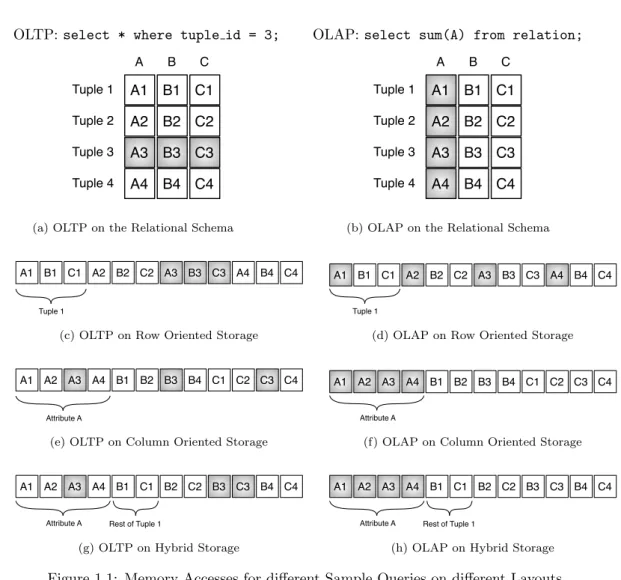
To illustrate the potential of hybrid storage consider the example in Figure 1.1. It shows two sample queries, an OLTP and an OLAP query as well as their access pattern on each layout.
1Horizontal partitioning, i.e., the storage of the values of one attribute in different layouts is possible but out of scope
CHAPTER 1. INTRODUCTION
OLTP:select * where tuple id = 3;
A1 B1 C1 A2 B2 C2 A3 B3 C3 A4 B4 C4 A B C Tuple 1 Tuple 2 Tuple 3 Tuple 4
(a) OLTP on the Relational Schema
OLAP: select sum(A) from relation;
A1 B1 C1 A2 B2 C2 A3 B3 C3 A4 B4 C4 A B C Tuple 1 Tuple 2 Tuple 3 Tuple 4
(b) OLAP on the Relational Schema
A1 B1 C1 A2 B2 C2 A3 B3 C3 A4 B4 C4
Tuple 1
(c) OLTP on Row Oriented Storage
A1 B1 C1 A2 B2 C2 A3 B3 C3 A4 B4 C4
Tuple 1
(d) OLAP on Row Oriented Storage
A1 A2 A3 A4 B1 B2 B3 B4 C1 C2 C3 C4
Attribute A
(e) OLTP on Column Oriented Storage
A1 A2 A3 A4 B1 B2 B3 B4 C1 C2 C3 C4
Attribute A
(f) OLAP on Column Oriented Storage
A1 A2 A3 A4 B1 C1 B2 C2 B3 C3 B4 C4
Attribute A Rest of Tuple 1
(g) OLTP on Hybrid Storage
A1 A2 A3 A4 B1 C1 B2 C2 B3 C3 B4 C4
Attribute A Rest of Tuple 1
(h) OLAP on Hybrid Storage
Figure 1.1: Memory Accesses for different Sample Queries on different Layouts
When evaluated on a row-store, the OLTP query accesses all values from one contiguous area2. The
OLAP query results in four random accesses to the memory in a row-store.
When evaluated on a column-store, the OLTP query induces three random accesses. The OLAP query can be evaluated by accessing one contiguous block, i.e., one random and multiple sequential accesses.
The last presented storage option is a hybrid layout (note that other hybrid layouts exist). Attribute
A is stored column-oriented whilst Band C are stored row-oriented. To evaluate the OLTP query, two
random accesses to the memory are needed. This is an increase compared to the row-store but still less than the column-store. For the OLAP query the hybrid store behaves just like the column-store.
Depending on the and the relative costs of random and sequential misses and the number of times each query is executed any of the presented layouts may have the least costs.
A hybrid DBMS would have to decide on the appropriate layout for every single piece of data. This decision is hard and can only be made if the usage pattern of each piece of data is known. This usage pattern is best derived from a Workload, i.e., a set of queries weighted with the frequency at which they are evaluated. Assembling a representative workload for a Database can be done upfront by a domain expert or by tracing the queries in a running instance of the database.
2Chapter 2 illustrates that reading data sequentially from a contiguous area of the memory is faster than reading data
1.2. PROBLEM STATEMENT
1.2
Problem Statement
Based on a given workload for a database we want to find the non-redundant, partitioned layout with the minimal overall query costs. To solve this problem it is necessary to solve two subproblems:
Finding an estimation for the query costs on a given layout that is as accurate as possible while still being computable in a reasonable time. Since the query costs are highly dependent of the hardware that runs the DBMS, the model has to take parameters of the hardware into account. The estimation should be based on a generic cost-model that allows an accurate estimation with few parameters.
Finding the partitioned layout with the least estimated costs for a given workload. Since au-tomated schema partitioning has been studied for a long time [16, 17, 18, 19, 20, 21, 22, 23] it seems reasonable not to develop a new solution from scratch but to use an existing approach and adapt it to our needs. This may pose some restrictions on the cost model that have to be identified and met to allow an optimal solution.
The focus of this work are in-memory databases [24, 2, 25, 26, 27, 28, 29, 30] because (a) they allow an easier model of the hardware since parameters that are unique to disk-based storage (number of disks, varying latency, failure rate, ...) can be neglected and (b) they have gained in practical relevance lately due to the decreasing cost and increasing capacity of memory chips. This development makes in-memory databases an interesting topic for research as well as compelling option for practical application.
The cost-model is expected to be generic enough to provide avery simplemodel of disk-induced costs
as well. Accurately modeling the specific effects of mechanical disk hardware is not possible with the an interesting challenge for future work.
1.3
Structure of This Work
The rest of this work is structured as follows: Chapter 2 gives the necessary background on in-memory databases and the hardware parameters that determine the performance of data accesses. The respective advantages of row- and column-based storage in an in-memory database as well as their origins will be discussed. In Chapter 3 the (existing) cost-model and our extensions are described. Some existing
approaches to vertical partitioning are introduced and extended to support hybrid partitioning. In
Chapter 4 we will show how these findings were incorporated in Spades, a tool that automatically
calculates an (analytically) optimal layout for a given schema, workload and hardware configuration. In Chapter 5 the accuracy of the cost-model is evaluated through a series of simple experiments. The
layouting performance ofSpades in a more complex scenario will also be evaluated. We will conclude
Chapter 2
Background on Database Storage
Performance
DBMS performance traditionally has been limited by the performance of the underlying storage de-vice [31]. The performance of many storage dede-vices has been tuned under the assumption of strong data locality (see Section 2.2.1). Traditional databases, that are either row- or column-oriented, often fail to provide the data locality that is needed for optimal performance [14].
Databases that allow the storage of relational data in either row or column orientation are called
Hybrid Databases in this thesis. Hybrid Databases allow to increase the locality of stored data with
respect to a workload which can in turn improve the data access performance. To maximize the benefit of this technique an arrangement of the data in memory has to be found that maximizes the data locality with respect to the underlying hardware and the workload. This requires some understanding of modern computer hardware and the way it is utilized for storage and processing in DBMSs.
In this chapter, the necessary background on modern computer hardware is provided and existing approaches that aim at increasing data locality for various database applications will be discussed. Since disk-based databases have been the focus of researchers for a long time, we will start with a very brief introduction to disk-based data access performance. Our investigation into main-memory data access performance will be initiated by challenging the assumption of constant-latency random access of the main memory through some simple experiments. The results are analyzed and explained and the determining factors for data access performance are illustrated. Following that, an overview over the caches in modern CPUs will be given. The chapter will be concluded with a description of existing research on data access performance of databases and the problem of optimal relational data storage.
2.1
Disk-Based Data Access Performance
Although not strictly the focus of this thesis, in this section, a short introduction to disk-based data access performance will be given. This allows us to draw parallels between disk-based and in-memory data access and helps to leverage some of the findings of disk-based data access research to the new area of in-memory databases.
The performance of disk-based data accesses are determined by a number of factors. The most important are [32]
(a) the disk rotation speed, which mainly determines the maximumtransfer rate and
(b) the seek time, which is the time it takes to locate an arbitrary piece of data and move the arm to its
position. This is the key factor to thelatency of the disk. The seek time may vary depending on the
distance by which the arm has to be moved. It is therefore usual to specify a minimal, a maximal and an average seek time.
The physical parameters themselves are not as much of interest to us as the effects they induce when accessing data: transfer rate, which is the same as bandwidth, and latency (see Section 2.2.2).
2.2. A PRIMER ON MAIN MEMORY DATA ACCESS
Transfer Rate Benchmarks of the harddisk in our test system, a Western Digital VelociRaptor
WD3000BLFS, show a maximal transfer rate of 119 MByte/s1. This transfer rate can only be achieved
for sequentially read data since sequential reads do not require a seek. Linuxfdiskreports a block size
of 512 bytes, which means that a block can be transmitted in 4.1 microseconds. When accessing data this way, about 31,2 million integer values can be read per second.
Latency The average (read) seek time of the WD3000BLFS is specified as 4.7 ms2. Adding the time for the transmission of a block, a random access to a value on this disk takes 4.741 ms. When reading
32bit integers that are spread (pseudo-)randomly across the disk3, every read integers induces a seek and
a block access. When accessing data this way, 211 integer values can be read per second. The factor
between the random and the sequential access performance is about 1,47e5.
This factor lead to the conclusion that the only determining factor for disk-based data accesses is the number of induced seeks [27]. While this is certainly oversimplified it gives an impression of the importance of data locality for disk-based DBMS: bandwidth is assumed to be virtually infinite but latency very high.
For main memory, however, the latency is supposed to be a constant, independent of the location of the accessed data. In the following section this assumption will be challenged.
2.2
A Primer on Main Memory Data Access
Before discussing the hardware factors that determine In-Memory DBMS performance specifically it is useful to know some more general properties of transistor-based memory. A good place to start is the assumption of true random access.
2.2.1
The Myth of Random Access
A computer’s main memory is accessed by the CPU by supplying an integer address and receiving the value that is stored at this address. In theory the main memory is a Random Access Memory (RAM), i.e., any value is supposed to be read in the same constant time. This sets it apart from non-random-access memory like a disk, CD or tape which may take an undetermined time to non-random-access a value [33, ps. 681 - 683].
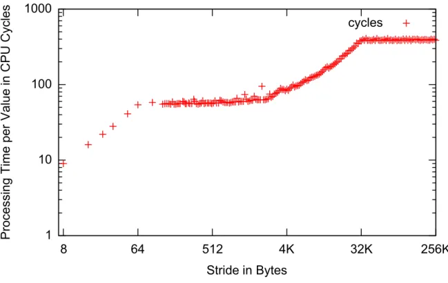
This theoretical assumption can be challenged with a simple experiment: a program that accesses a constant number of addresses but varies the distance (stride) between them. When plotting the average processing time per value in dependence of the stride we would expect an even graph — the execution time should be the same for every stride because every access of a value should take the same constant time.
Figure 2.1 shows a plot of the results of this simple experiment (see Appendix A.1 for the source code)
when executed on our test system, anIBM BladeCenter HS21 XM with an Intel Xeon E5450 Processor
(3 GHz) and 32 GB RAM. The plot does not show the expected uniform access costs. Instead, it shows that the wider the stride the more time is spent processing a single value up to a stride of 32KByte after which the costs are constant. There are also several points of discontinuity in the curve.
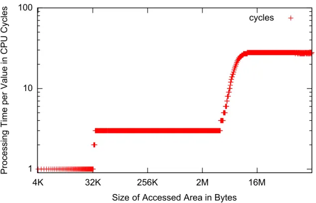
Figure 2.2 shows a plot of the results of a similar experiment (see Appendix A.2 for the source code). In this experiment the stride was kept constant (64 bytes) and the size of the accessed area in memory was varied (the number of accesses was constant). The plot shows virtually constant costs up to six megabytes. After that point the costs are increasing steeply up to six megabytes. After that they are constant again.
These plots show that RAM is indeed not a random access memory and provides motivation for an investigation into the reasons. Especially the points of discontinuity appear interesting. To understand the reasons for the different access costs it is necessary to understand the operating mode of the hardware
1available athttp://www.storagereview.com/WD3000BLFS.sr
2Vendor specification is available athttp://www.wdc.com/en/products/products.asp?driveid=494 3This happens e.g. when accessing a tuple in a column-store
CHAPTER 2. BACKGROUND ON DATABASE STORAGE PERFORMANCE
1
10
100
1000
8
64
512
4K
32K
256K
Processing
Time
per
Value
in
CPU
Cycles
Stride in Bytes
cycles
Figure 2.1: Costs of a Data Access with varying stride
components that influence memory access performance. Most of them are tuned under an assumption calledData Locality.
Data Locality
A data access pattern that many applications expose is known as Data Locality [33]. Data that has a
strong semantic relationship, like two attributes of an object or struct, are stored close to each other in memory, i.e., the difference between their addresses is small, and often accessed together. This is called Spatial Data Locality. Data locality is also exposed in the dimension of time (Temporal Data Locality): data with a strong semantic relationship is often accessed over a relatively short time. A special case of temporal data locality is the repetitive access of the same piece of data over a relatively short time. Hardware vendors have recognized this pattern and adopted their hardware to it. Data accesses according to this assumption are performed faster than arbitrary data accesses. Most commonly this is done by storing data in blocks, areas of the memory with a common size and a predefined position. Access to multiple values in one block is usually much faster than access to values from multiple blocks. It is therefore sensible to develop applications according to this pattern to take advantage of the hardware optimizations that assume data locality.
When talking about data locality the concept ofBlocked Data Localitywill sometimes be used in this
thesis.
Blocked Data Locality means that it is not necessary to store data items that are accessed together as close as possible but merely within a block of the respective memory layer to achieve optimal performance.
Absolute Data Locality means data locality where data items that are accessed together are stored as close as possible in the memory.
2.2. A PRIMER ON MAIN MEMORY DATA ACCESS
1
10
100
4K
32K
256K
2M
16M
Processing
Time
per
Value
in
CPU
Cycles
Size of Accessed Area in Bytes
cycles
Figure 2.2: Costs of a Data Access to an Area of Varying Size
2.2.2
Determining Factors for Data Access Performance
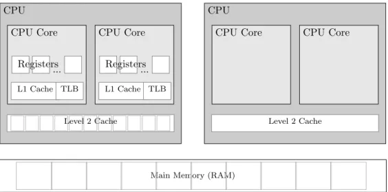
The memory structure between RAM and a modern CPU usually includes the CPU registers, at least two levels of CPU caches and the RAM itself which in turn is organized into blocks. Figure 2.3 shows a diagram of the hardware components of our test system that have an impact on the memory data access performance. A detailed description of the impact each component has will be given in Section 2.2.3. For now, it is enough to know that data that is about to be processed is transmitted from the RAM towards the CPU Cores through each of the memory layers. Every layer provides a cache for the underlying layer which decreases the latency for repetitive accesses to a piece of data. A request to a piece of data that is not currently stored in a cache is called a miss [33]. A full miss, i.e., a needed piece of data that is only present in the RAM, results in an access to the RAM and the transmission through all layers of memory. The time this takes is determined by two factors: the (minimal) bandwidth and the latency of the RAM [33, p. 393].
Bandwidth
The (digital) bandwidth of a data transmission channel is the amount of data that can be transmitted through the channel in a given time [34]. It is usually measured in bytes or bits per second. When processing data from the RAM it has to be transmitted to the processing core through a number of channels:
from the RAM through the Front Side Bus (FSB) to the Level 2 Cache
from the Level 2 Cache through the CPU-Internal Bus to the Level 1 Cache
and from the Level 1 Cache through the Core-Bus to the Registers of the CPU Core.
The bandwidth of the channel from RAM to CPU Core is the minimal bandwidth of any of the channels. Some channels like the Front Side Bus or the CPU-Internal Bus are shared between multiple processing
CHAPTER 2. BACKGROUND ON DATABASE STORAGE PERFORMANCE
CPU
Level 2 Cache
CPU Core CPU Core
L1 Cache TLB L1 Cache TLB ... Registers CPU Level 2 Cache CPU Core CPU Core ... Registers
Main Memory (RAM)
Figure 2.3: Schema of the Relevant Hardware for In-Memory DBMS
units (Cores) which may decrease the effective bandwidth of the channel.
Latency
The Latency of a storage device is the time between the request of a piece of data and the beginning of its transmission. The latency of transistor-based memory is comparable to the seek time of a harddisk (see Section 2.1) in its effect. The cause however, is very different: instead of the mechanical inertia of the disk arm it is the time to decode a memory address and connect the transistors that contain the requested piece of data to the bus [32]. For caching memories the latency also originates from the time it takes to determine if, and if so where in the memory, a given block is cached (see Section 2.2.3).
The Relation between Latency and Capacity of Memory
Even though latency has been a known problem for some time, effective solutions to the problem are still lacking [25]. The most common approach to decreasing the latency is to simply increase the clock rate of the transistors. This is limited by physical constraints. A major factor is the high address decoding and transmission effort for hierarchical high capacity memory [33, p. 448 - 455] [35, 32]. Memory is addressed using contiguous integer values by programs but is physically accessed by activating or deactivating the charge on pins of the memory chip. The translation of the integer address to the tuple of activated
pins is called address-decoding and takes a time that scales linear with the width of an address4 [33,
p. 448 - 455]. Since larger memories need wider addresses, transmitting and decoding these addresses becomes increasingly time-consuming. This makes it currently impossible (let alone cost effective) to build a large memory, like the RAM, with a low latency. This also means that low latency memory like the Level 1 Cache has a relatively low capacity.
Block Access Time
Applying the principle of data locality to the problem of memory latency, a very simple solution is reasonable: data is always accessed in blocks. This does not diminish the latency but only induces it per block instead of per data-word (the width of the system Bus, most commonly 64 bits). Consistency requirements in each memory layer make it necessary that a full block is transmitted before a new block can be accessed. Thus latency, transmission bandwidth and block size can be combined into the
Hit Time [33] or Block Access Time (BAT), the time it takes to activate and transmit a block from a
memory layer to the next.
2.2. A PRIMER ON MAIN MEMORY DATA ACCESS
Knowing the latency, access-bandwidth and block size of each memory layer the BAT can be calculated using Equation 2.1.
BAT = latency+ blocksize
bandwidth (2.1)
In the following the BAT will be used as the primary metric to determine the cost of a memory access. This is valid since every access to a memory layer takes time for activation and transmission [32].
2.2.3
Caches in Current CPUs
To speed up data access on high capacity main memory, most current CPUs include one or many low-latency/low-capacity caches. Data accesses that fulfill the assumption of data locality can greatly benefit from these caches. In this section their most relevant properties will be discussed.
Cache lines
Caches usually do not cache single values but rather blocks an equal number of values. These are called Cache Lines. Cache Lines are the atomic storage unit of a cache. A cache can not contain a strict subsets of a cache line. If one value of a cache line is modified, the whole cache line is written back to the memory [33]. Cache lines start at predefined positions that do not overlap and span the whole cacheable memory.
Slots
The capacity of the cache is defined by the size of a cache line and the number of available storage slots. Since the cache is generally much smaller than the cached memory, the mapping of a block of addresses to their cache line is not trivial. One slot can hold one of many addresses and an address could potentially be cached in one of many slots. The mapping of memory addresses to the set of possible slots is defined by theassociativity of the cache.
The Relation between Latency and Capacity of a Cache
The relation between the latency and the capacity of a memory has been discussed in Section 2.2.2. For caching memories, the latency is increased even further with their capacity because a fully associative cache could store a cache line in any location [33]. When trying to locate a cache line all location have to be checked [33]. The impact on the latency is obvious. To decrease the latency it is common to allow
only a few locations for a given memory address. In such aSet Associative Cache, only those locations
have to be checked. This may however result in early evictions which will be discussed Section 3.1.4.
Evictions
Due to it’s relatively small capacity, the cache is filled fast when operating on large datasets. It is therefore necessary to remove a cache line before a new one can be loaded into the cache. Which cache
line is evicted is determined by theEviction Strategy. For the rest of this thesis we will assume aLeast
Recently Used (LRU)eviction strategy, which means that the cache line which has not been accessed the
longest is evicted.
Address Translation
Another layer of blocks that has to be considered is introduced by the caching of the mapping from virtual to physical addresses. The emerging of multi-processing made it necessary to protect the address space of one process from access by another process. This protection is provided by the operating system
through the concept of Virtual Memory [33]. Every process that requests memory from the operating
system is supplied with an area of memory that is marked as belonging to this process. This happens transparently to the process: it can access its private virtual memory as a contiguous space using integer
CHAPTER 2. BACKGROUND ON DATABASE STORAGE PERFORMANCE
!"#$ %&'()*
+,-./-32-bit paging may map linear addresses to either 4-KByte pages or 4-MByte pages. Figure 4-2 illustrates the translation process when it uses a 4-KByte page; Figure 4-3 covers the case of a 4-MByte page. The following items describe the 32-bit paging process in more detail as well has how the page size is determined:
•
A 4-KByte naturally aligned page directory is located at the physical address specified in bits 31:12 of CR3 (see Table 4-3). A page directory comprises 1024 32-bit entries (PDEs). A PDE is selected using the physical address defined as follows:— Bits 39:32 are all 0. — Bits 31:12 are from CR3.
— Bits 11:2 are bits 31:22 of the linear address. — Bits 1:0 are 0. *#0#1 +234567')7889:44)&;)<2:)!"=>3<:)7'5?@:8)A7?:)859:6<&93)B4:8);&9)'5@:79"7889:44) <97@4'7<5&@ C*0*1 .?@&9:8)D<2:4:)E5<4):F54<)&@'3)&@)A9&6:44&94)4BAA&9<5@?)<2:).@<:'"C!)79625<:6<B9:G !"#$%&'()*+'',"-&.%)/00%&11'2%.-13.4"5-'45'.'()6784&'9.#&'$1"-#':*)7"4'9.#"-# 2.;3&'():+''<1&'5='>?:'@"4A':*)7"4'9.#"-#'B>5-40+C 7"4' 951"4"5-B1C >5-4&-41 0 Directory Table Offset
Page Directory PDE with PS=0 CR3 Page Table PTE 4-KByte Page Physical Address 31 22 21 1211 Linear Address 32 10 12 10 20 20
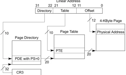
Figure 2.4: Address Translation of a 32 Bit Address in the Intel Core Architecture (taken from [1])
addresses. Since the address spaces of multiple programs may be interleaved the virtual address has to be mapped to the physical address where the data is stored. This mapping is based on a number of parameters (including the process id, the virtual address and parameters to manage shared address
spaces) and takes time. To speed up address translation the result is cached in theTranslation Lookaside
Buffer (TLB). In general, the TLB caches only a pointer to the first address of a block of memory addresses. The size of such a block is dependent of the system. Most common are 4 KByte with an option of switching to large pages of 2 MByte each [1]. These blocks are called (virtual) memory pages and introduces another blocking of memory.
If a TLB miss occurs, the virtual address has to be translated into a physical address. Figure 2.4 illustrates the address translation of a 32 Bit address in the Intel Core Architecture. A miss in the TLB
results in a lookup in the Page Directory using the first 10 bits of the address. The entry in the Page
Directory designates the address of a Page Table which holds 210 = 1024 Page Table Entries (PTEs).
The PTE is a pointer to the starting address of the physical memory page. The next 10 bits of the address are used to select the PTE from the Page Table. This pointer is cached in the TLB. The Page Directory as well as the Page Table are stored in the regular main memory. Therefore, each of the lookups may induce a Level 2 Cache miss.
Writing to the Memory Through Caches
Reading a cache line from the memory results in a single fetched cache line. Writing the memory,
however, is more complicated. Depending on the write strategy (write through orwrite back [33]), data
is written to the underlying memory either immediately (write through) or delayed until the modified cache line is evicted (write back). All modern Intel [1] as well as AMD [36, page 170]CPUs allow picking the write strategy per address (block). Our experiments (see Section 5.2) indicate that heap variables are always stored in a write through block (by the used compiler). This makes modifications that are made in one thread immediately available to all other threads. Therefore, every modification would block the memory and induces costs like a cache miss. If multiple modifications are made within “a small window
of time” [1, Vol. 3, page 11-12] they are buffered in aWrite Combine buffer and written consecutively.
This optimization makes a write through behave like a read. We will therefore treat it just like a read. Stack variables are stored in a write back block (by our compiler). The data is written to the memory once the modified (a.k.a. dirty) cache line is evicted. Integrity constrains make it necessary to fetch the (unmodified) rest of the cache line on a write [1, Vol. 3, page 11-10]. This induces a cache miss on the first modification of a cache line in addition to the miss induced by the writing. Unless a cache line is accessed is modified many times the additional miss decreases application performance.
2.2. A PRIMER ON MAIN MEMORY DATA ACCESS
the heap and thus in a write through block. We will therefore assume a write through cache for the rest of this thesis. Investigating in the performance implications of a different writing strategy is left for future work.
Prefetching in the Level 2 Cache
Memory Cache CPU R e q u e st Fetch 1 R e q u e st Act iva te Fetch 1 T ra n smi t T ra n smi t Load Load Value 1 Value 2 T ra n smi t Load Pro ce ss Value 1 R e q u e st Fetch 3 R e q u e st Act iva te Fetch 3 Value 3 Tra n smi t T ra n smi t Load Load Value 4 T ra n smi t Load Pro ce ss Value 3
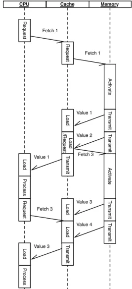
Figure 2.5: Activities on the Different Memory Layers when Processing Values without Prefetching
To reduce the penalty when retrieving a cache line from the underlying memory layer some caches try to anticipate the line that will be accessed next and start fetching it before it is
requested [33, 37]. This is called Prefetching
and will be discussed in this section.
Processing without Prefetching Values that are not present in any of the CPU caches are requested from main memory before be-ing processed. After the activation latency of the memory the transmission of data begins.
This usually happens in the so called Burst
Mode: not only the requested data word is transmitted but a whole block of words with-out the CPU explicitly requesting them. The size of a burst is usually the same as the size of a cache line. This allows efficient filling of a cache line without additional overhead for ad-dressing all words individually. Assuming data locality this improves the performance.
Figure 2.5 shows a sequence diagram of the caches and the CPU processing one value from a cache line. First, the CPU requests the value of address 1 which is not present in the cache. The cache requests the address from the memory, which triggers a burst of the block that contains the address. The memory trans-mits all values from the block to the cache, the CPU stalls. When the cache line is trans-mitted completely, the CPU starts processing the requested value and the memory/Bus is idle. When the CPU finished processing the requested values, it requests the next piece of relevant data. In the example, this induces an-other cache miss which triggers anan-other burst of values from the memory. As illustrated in Figure 2.5, the CPU and the memory spend time idle while the other is working.
Prefetching Strategies Since the Memory Bus is the main limiting factor for data trans-mission performance [25], keeping the Bus busy is crucial for the overall performance. This can be done by transmitting data that
has“not yet”been requested by the CPU.
Ap-plying the principle of data locality it is rea-sonable to transmit data that is located near
CHAPTER 2. BACKGROUND ON DATABASE STORAGE PERFORMANCE
the currently accessed. Whether any prefetching is triggered and if so which cache line will be prefetched
is determined by the prefetching strategy. The Intel® Core Microarchitecture [1] e.g., defines two
different prefetching strategies for the Second Level Cache [38] :
The Data Prefetch Logic (DPL)(the default) is a sophisticated prefetcher that attempts to recognize
strides (consecutive accesses to addresses with a constant distance) and anticipate the next fetched cache line based on the recognized stride. The second prefetching strategy is the
The L2 Streaming Prefetcher that simply fetches the next adjacent cache line.
The prefetching strategy can be selected or completely disabled at runtime usingMachine Specific
Reg-isters. Memory Cache CPU R e q u e st Fetch 1 R e q u e st Act iva te Fetch 1 Value 1 Tra n smi t T ra n smi t Load Load /R e q u e st Value 2 T ra n smi t Load Pro ce ss Value 1 Act iva te Value 3 Value 4 Fetch 3 Value 3 R e q u e st Load T ra n smi t T ra n smi t Load T ra n smi t Load Pro ce ss Fetch 3
Figure 2.6: The Effect of Correct Prefetching The correct prediction of the next
re-quested cache line and it’s transmission will be
called correct prefetching. An incorrect
pre-diction and the transmission of a cache line
that will not be requested is called incorrect
prefetching. The effect of either will be dis-cussed in the following.
The Benefit of Correct Prefetching Cor-rect prefetching can improve the bandwidth utilization by keeping Bus and memory busy and thus improve the overall performance. Figure 2.6 shows the beneficial effect of cor-rect prefetching. Again, the CPU starts by re-questing value 1 and stalls while the cache line is transmitted. When the last piece of data has been transmitted to the cache, the CPU processes it. At the same time, the prefetch-ing unit of the cache fetches the next cache line (the one containing value 3 and 4). Since the prefetching was correct, the CPU requests value 3 when it has finished processing value 1. The memory has already started transmit-ting it and the cache has a head start. In the best case the complete cache line has already been loaded and the cache can supply the CPU with the values right away. This shortens the stalling periods keeping the Bus and the CPU busy which in turn increases the data through-put of an application.
The Effect of Incorrect Prefetching
Whilst correct prefetching can improve perfor-mance, incorrect prefetching can lead to a de-crease in application performance. This is due to the fact that any fetch, regular or prefetch,
blocks the memory and the Bus. Since a
memory burst cannot be interrupted once it is started, Bus and memory are blocked until
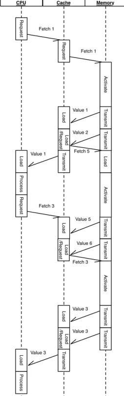
the end of the burst. In case of an incorrectly fetched cache line this prevents the transmission of the correct cache line. Figure 2.7 illustrates this effect. The CPU requests the value 1 and processes it. When the transmission of the first cache line is complete, the prefetching unit triggers the (incorrect) prefetching of value 5 and 6.
2.2. A PRIMER ON MAIN MEMORY DATA ACCESS Memory Cache CPU R e q u e st Fetch 1 R e q u e st Act iva te T ra n smi t T ra n smi t Fetch 1 Load Load /R e q u e st Value 1 Value 2 T ra n smi t Load Pro ce ss Value 1 R e q u e st Load T ra n smi t T ra n smi t Load Value 5 Value 6 Fetch 5 Act iva te Fetch 3 Load /R e q u e st Act iva te T ra n smi t T ra n smi t Fetch 3 Load Load /R e q u e st Value 3 Value 3 T ra n smi t Load Pro ce ss Value 3
Figure 2.7: The Effect of Incorrect Prefetching When the CPU is done processing value 1, it
requests value 3 but the burst of value 5 and 6 has already been triggered and has to be com-pleted. The cache has to wait until the trans-mission is completed before value 3 can be re-quested from the memory. Prefetching value 5 and 6 blocked the Bus and prolonged the stalling of the CPU.
In addition to blocking the bus, incorrectly prefetching a cache line evicts a cache line
from the cache. This can effectively double
the penalty because the evicted line may be requested again later on, which induces an ad-ditional cache miss. In our experiments (see Section 5.2) the additional evictions had only minor influence on the overall performance and were, therefore, is not considered in the model.
The Performance Impact of the Prefetch-ing Strategy When comparing Figures 2.6 and 2.7 one may notice that the penalty of an incorrectly prefetched cache line may be very high in comparison to the benefit for a cor-rectly prefetched one. A good and above all cautious prefetching logic is therefore crucial to preserve the positive effects of prefetching.
The Data Prefetch Logic is such a cautious
strategy since it only triggers prefetching on detection of a constant stride. For some appli-cations this may be too cautious and may not trigger any prefetches even though the applica-tion may benefit from them (see Secapplica-tion 3.1.4). In these cases it may be beneficial to change the prefetching strategy to one that better suits one’s needs (HYRISE allows to change the prefetching strategy per relational opera-tor).
2.2.4
Blocks
in
the
Memory
Modules
In addition to the blocking that is introduced by the caches, the memory modules themselves are blocked too. The memory chips are orga-nized in a matrix [32]. To address a cell in the matrix a row and a column address have to be provided. The memory modules do, however, keep a row active after a value has been trans-mitted. When accessing a value from the same row it is therefore unnecessary to readdress a row. The mapping of the integer addresses to
a row and a column address is performed by the memory controller. It receives the address and deter-mines the row at which the requested address is located. If the row differs from the last accessed row,
CHAPTER 2. BACKGROUND ON DATABASE STORAGE PERFORMANCE
the controller sends a command to the memory module to change the selected row. This command is
called the Row Address Strobe (RAS) Signal. After that, the column is calculated and a command is
issued to access the value. This is called theColumn Address Strobe (CAS) Signal.
2.3
Data Access Performance of Different Database
Manage-ment Systems
Database Performance on modern CPUs is very much I/O-Bound [25]. The query throughput is not limited by the processing speed but by the speed at which the processor can be supplied with the necessary data. It is therefore crucial to make good use of the available bandwidth and avoid latency stalling.
As seen in Section 2.2, hardware vendors often tune hardware to improve the performance for ap-plications that expose a strong data locality. It is relatively easy to develop apap-plications according to this assumption if the usage pattern of the data is known in advance. For a DBMS that is not aware of the it’s usage pattern in advance one design does not fit all. The application of a database is greatly influencing the usage pattern of the held data and thus the optimal arrangement of data in memory.
In this section the existing approaches to improve the data locality for a known workload in managed databases will be presented.
2.3.1
In-Memory Database Management Systems
While the disk used to be the only storage option, the decreasing (physical) size and costs of transistors made an increase in memory capacity possible. This made it feasible to use the RAM as the primary storage and benefit from its superior performance in terms of bandwidth as well as latency.
Many large DBMS vendors recognized the potential of in-memory DBMSs and already ship or at least announced in-memory data management solutions. These are either mere caches for disk-based DBMS like Oracles TimesTen [26] or standalone solutions using the memory as the primary storage and the disk only as a backup like IBMs SolidDB [39].
Since the bandwidth as well as the latency of RAM are outperforming disks by some orders of magnitude a performance benefit in this dimension is expected. When carefully designing an in-memory DBMS this advantage in data access speed can be leveraged to build high performance DBMSs. As shown in Section 2.2 the determining factors for in-memory data access performance are similar to those determining disk-based performance.
Existing research on data storage strategies for in-memory databases will be discussed in this section.
First In-Memory DBMS Implementations
With the decrease of transistor size, RAM capacities grew to a size that allowed storage of a reasonably sized database. In the 1980’s, research on in-memory DBMS began [40].
At that time, blocked data transmission, as described in Section 2.2.3, was not as common as it is today. The burst mode for RAM-modules was patented in 1985 [41] and standardized e.g. in the Burst EDO RAM in 1996 [42]. The first Intel CPU with an integrated cache was the i486DX that was introduced in 1989 [32]. In 1992 Garcia-Molina and Salem [27] described the main memory as “not block-oriented” — the RAM was still considered a random access memory. Under this assumption it was reasonable to disregard existing findings on data locality that originated from disk-based DBMS and base the storage layout purely on concerns of the implementation. An implementation that followed this assumption is MM-DBMS [28]. As shown in Section 2.2.1 the assumption of true random access does no longer hold true: In-Memory Databases now follow rules that are very similar to those for disk-based databases and therefore many of the existing optimizations can be reused.
2.3 Data Access Performance of Different DBMSs
Row-Based DBMS
Traditionally, relational structures have been mapped to the one-dimensional memory strictly
record-wise. All attributes are written to a consecutive area in memory, one slot followed by the next [43] 5.
In terms of data locality this means that there is a strong locality between the attributes of a tuple. For a transactional application this seems the most suitable layout because transactional queries usually operate on few tuples and often access many attributes. The strongest representative of transactional
queries is the INSERT-statement that accessesmany or all attributes of asingle tuple.
On the other hand, storing data in this layout means that the values of the same attribute but of different tuples are at least separated by the length of one tuple. The consequence is a very low degree of data locality for the values of an attribute. Analytical queries, that usually access values of few attributes but many tuples, are therefore executed on a suboptimal storage layout.
This effect has been recognized by database administrators and lead to research regarding decomposi-tion of reladecomposi-tions. Since attribute values are separated by at least a tuple length the data locality between them can be increased by reducing the length of a tuple. The most extreme case of this technique is called Decomposition Storage Model (DSM) [20]. When stored in DSM every attribute of a logical relation is stored in one physical relation together with the id of the tuple. This reduces the distance between two values of an attribute to exactly the size of the id and thus increases its data locality. DSM has a major disadvantage: all queries that access more than one attribute have to be rewritten to reconstruct the logical tuples from the physical relations using a join on the id. Since the selectivity is expected to be low for such OLTP queries an indexed join is most appropriate for tuple reconstruction. This does however result in additional costs for write intensive workloads because every insert of ann-tuple triggers ninserts into the indices.
If supported by the DBMS implementation it is possible to remove the explicit id and the needed index from the attribute’s relation and use an implicit id that is calculated from the memory address (e.g., id=address(tuple)−of f set). This greatly simplifies the tuple reconstruction and is therefore a very sensible optimization [6]. A database that stores all relations in DSM and does the reconstruction transparently is called column-oriented [3].
Column-oriented DBMS
Column-based DBMS [6, 7, 44, 3] store all data in single-value columns: the values of a given attribute of all tuples are stored in a (practically6) contiguous area in memory. As an alternative, several strategies have been proposed to allow column-based storage on the level of storage pages instead of the level of relations [45, 46].
Both approaches increase data locality between values of an attribute and are therefore suited for analytical applications. For transactional queries however column-stores face the same problem as DSM on row-stores: logical tuples have to be reconstructed from the physically stored relations.
Tuple Reconstruction in Columnstores A drawback of a column oriented data storage is that a single tuple is spread over as many locations as it has attributes. When a tuple is requested, the DBMS
has to reconstruct it from these locations. n requested attributes result inn(pseudo-)random accesses
to the memory. Unless many tuples are requested and the values for their attributes are located on a
single memory block this also results in n block accesses per tuple. If the value for an attribute only
occupies a fraction of the block, transmitting the rest wastes memory bandwidth.
Late Materialization The high number of memory accesses for the reconstruction of requested tuples
has been recognized and tackled through a technique called Late Materialization [7]: the requested
tuples are passed from relational operator to relational operator (see Section 3.1.1 ) not in their actual representation but as an integer id. When the values of an attribute are needed by an operator they are read from the stored relation using the tuple id. If the number of tuples decreases during the evaluation
5not all slots have to be filled at all times
6Even though suboptimal memory management will sometimes split the area in memory we assume that the number
CHAPTER 2. BACKGROUND ON DATABASE STORAGE PERFORMANCE
of the operator tree the number of cache misses that is induced by tuple reconstruction is decreased. If an attribute is used by more than one operator, however, it is read from the stored relation multiple times. Depending on the selectivity of the operators this can increase the number of cache misses. In this case
anEarly Materialization is suited best. Abadi et al. [7] have shown that picking the most appropriate
materialization strategy is not trivial.
Indices A common misconception about column-stores is that they do not need indices to efficiently locate a stored tuple [6]. Indeed, the costs of a single attribute scan in a column-store are lower than the costs of the same scan in a row-store. The decreased costs are due to the reduced number of memory blocks that have to be read. Column-oriented storage will, however, only decrease the costs by a constant factor. The complexity of a scan is still inO(n) while an index lookup is inO(log (n)). Thus an index that speeds up a row-oriented also speeds up a column-oriented database in the same manner. The problem of automatic index selection [47, 48] is orthogonal to the problem of optimal cache conscious storage and is considered out of scope of this thesis.
Existing Hybrid DBMSs
Similar to column-oriented storage, hybrid storage can be implemented on the layer of logical relations or on the layer of data storage pages. EaseDB [24] is an implementation of the first, Data Morphing [17] of the second approach.
The capability of hybrid storage introduces new options for database optimizations but also makes the process of optimization more complex. The layout with maximal data locality for a given workload
depends on the usage pattern of every piece of the stored data. The optimal layout can therefore
only be found if the usage pattern is known in advance. Database administrators can, based on their experience, extrapolate the usage pattern from informal application requirements. EaseDB, e.g., relies on the manual definition of the partitioned, oriented schema by an administrator. This is, however, expensive and possibly error-prone. It is therefore desirable to automate this process.
Data Morphing adapts the schema at runtime using a very simple cost model. The Data Morphing technique has two important drawbacks:
1. the cost model only considers a single layer of blocked caches without further optimizations (like prefetching, parallel address translation, ...) and
2. the running time of the layout algorithm scales exponentially with the number of attributes of a relation which makes it unfit for wide tables.
To improve the automatic optimization a model is needed that takes account of the workload and specific parameters of the hardware.
HYRISE A prototype of a hybrid DBMS is currently developed at theHasso Plattner-Institut. It is
called HYRISE [49] and, as this is written, still in a very early stage of development. So far it consists
of a hybrid storage layer and implementations of the most important relational operators on top of that storage layer. The operators allow early as well as late materialization (see Section 2.3.1).
As we have seen in this chapter there are a number of hardware parameters that have to be taken into account. Due to the blocked storage of data it is not necessary to achieve absolute data locality but merely blocked data locality for optimal performance. Since there may be many layers of blocking with different Block Access Times and block sizes a detailed model of the hardware is needed to find an optimal layout. Such a model will be discussed in the next section.
Chapter 3
Data Layouting based on Estimated
Query Costs
As illustrated in the last chapter, the performance of a DBMS largely depends on the data access performance. Since data is always accessed and cached in blocks, the data access costs can be measured in the number of cache misses that are induced in each of the memory layers. Based on this finding, a model can be developed to estimate the execution costs of a given query by estimating the number of cache misses. Hardware parameters and the storage layout have to be taken into account for this estimation. Such a model is described in Section 3.1. How to use this model to automatically find an (analytically) optimal storage layout for a given workload will be discussed in section 3.2.
3.1
Query Cost Estimation
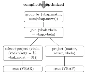
select matr, sum(netwr) from VBAK,
VBAP where aedat = $1 and vkorg = $2 and
vbak.vbeln = vbap.vbeln group by matnr
compiled + optimized group by (vbap.matnr, sum(vbap.netwr)) join (vbak.vbeln = vbap.vbeln) select+project (vbeln, (vbak.vkorg = $2, vbak.aedat = $1)) project (matnr, netwr, vbeln)
scan (VBAK) scan (VBAP)
Figure 3.1: An Example of a Relational Operator-Tree To estimate the costs of a query, it is not only
necessary to know the query itself, but also how it is evaluated by the system. Since most DBMSs base their query execution on rela-tional algebra, this section will be started with a very short recapitulation of relational algebra and it’s use in DBMSs. This will be followed by an overview of existing research on query cost estimation. In section 3.1.3, the model that was used in this thesis will be described followed by a description of the extensions that were made. How to model a query processor is illustrated in section 3.1.5.
3.1.1
Relational Algebra
Even though most DBMSs use a higher level querying language like SQL for their external interface, most of them rely on relational al-gebra [43] (or a dialect of it) to represent a query internally. When a query is entered into the system it is first compiled to a relational algebra tree which is then optimized and ex-ecuted. Figure 3.1 shows an example of such a relational operator tree. For a description of the used operators the reader is referred to [43].
CHAPTER 3. DATA LAYOUTING BASED ON ESTIMATED QUERY COSTS
The tree is then processed bottom up. Every operator is executed and produces the input for the next. Data flows from the bottom to the top where it is returned as the result of the query. The operator tree is, thus, a high level description of how the query is evaluated. To reflect this way of evaluating queries it is reasonable to start cost estimation the same way: by compiling SQL to relational algebra. Implementing a simple SQL to relational algebra compiler is fairly straight forward and well
documented [43]. Section 4.2 describes how the compiler component ofSpades has been implemented.
Insert Queries in Relational Algebra Relational algebra is an algebra to query relations, not to modify them. It is not possible to express a modifying query with the relational operators [43]. Therefore, DBMS implementations have to find another way to represent updates/inserts. In terms of memory access, however, insert/update queries do not differ from accesses to a single tuple: both have
to locate a memory region of one tuple (or an empty slot for an insert) and access it 1. We, therefore,
represent an insert query as a selection on the tuple id. As explained in Section 2.2.3, writing to memory through the cache generally induces no different costs than reading it.
Implementation of Relational Operators The functionality of an operator is usually implemented in the native language of the DBMS. The description of the implementation in a form that can be used
to estimate the execution costs is difficult. One way to describe the implementation areaccess patterns,
a concept that is part of the generic cost model [2] that is used in this thesis. In the next section, we will give an overview of alternative models, followed by a detailed description of the generic cost model as defined by Manegold et al.
3.1.2
Query Cost Estimation
Estimating the costs of a query is necessary for query as well as layout optimization. It is generally desirable to estimate the costs in a metric that has a total order (e.g., a simple integer value). This allows to compare two values in the metric and determine which one is “better”. To calculate this value, the model may use any number of intermediate metrics. As explained in Section 2.1, e.g., disk based DBMS performance is often measured in the number of induced seeks and the number of read bytes. The costs are derived from that. Simple models like the one used in [43, pgs. 441ff.] calculate the costs from one metric, e.g., the page I/O-operations.
To find the optimal query plan, a query optimizer needs to compare different plans for a single query. Consequently, the costs have to be derived from the operator tree. A layout generator, since it is only interested in the relative costs of queries to each other, may use a cost model that estimates the costs directly from the query. We will discuss both approaches in the following.
Estimating Costs directly from the Query
Data Morphing [17] is an approach to the layouting problem that estimates the costs directly from the query. It relies on an input that specifies the percentage of the values that are accessed of every attribute. From that, the number of induced cache misses per tuple is estimated using a simple formula. This is done under a number of assumptions:
the values of all attributes are accessed in a uniform and random fashion,
a read cache line is not removed from the processor cache before all the values in that cache line
have been processed and
all operations are execute on an empty cache
While these assumptions may hold for simple queries that can be evaluated in a single scan of attributes, it fails for complex queries that involve intermediate results or repetitive accesses to values (joins, group-bys, late materializing operators, ...).