Framework and User Migration Strategy of
Cloud-Based Video Conference Multi-Gateway
System
Hongen Feng
1, Wenjun Wu
21,2State Key Lab of Software Development Environment
School of Computer Science and Engineering, Beihang University Beijing, China
[email protected], [email protected]
Abstract—In video conference system, the multimedia gateway
plays an important role in forwarding audio and video data, whose performance is a bottleneck of the system. A flexible framework of cloud-based video conference multi-gateway system is proposed to meet the needs of a high-definition video conference system, which can control a variety of virtual gateway resources based on physical devices, thus multimedia gateways can be deployed dynamically. In addition, a real-time user migration strategy is designed and implemented based on the framework, which combines active pattern with passive pattern. The experiments show that the user migration strategy could control the time delay of user migration under 65 milliseconds, ensure the continuity of audio and video data during user migration, and successfully solve the reliability problems caused by system shutdown or overload of the multimedia gateway.
Keywords-cloud computing; multi-gateway system; user migration strategy
I. INTRODUCTION
A multimedia video conference is the real-time exchange of media data among several parties, which breaks the limit of human communications due to the geographical location of participants. Recent advances in broadband communication and computing technology have accelerated the proliferation of multimedia conferencing services in large-scale enterprises, and a high quality multimedia conferencing has been an urgent requirement these years. However, the products in the market are immature, and they cannot support a large number of participants and multiple HD videos in a meeting.
Meanwhile, cloud computing [1]-[4], a new thing which is
only five years old, becomes the most fashionable technology and developing trend in IT industry now. As a result, it is a popular topic for blogging and white papers and has been featured in the title of workshops, conferences, and even magazines. There is no standard formal definition of cloud computing, broadly speaking, cloud computing is an architecture where IT resources (compute, storage, platforms, applications and services) are pooled and delivered to the users on-demand without strict dedicated association of customers and resources. The services of Cloud computing can be divided into three main categories: Infrastructure-as-a-Service (IaaS), Platform-as-a-Service (PaaS) and Software-as-a-Service (SaaS).
In video conference system, multimedia gateway plays an important role in forwarding audio and video data. Most conference models are built on a single centralized conference server, which has only one multimedia gateway, for the effective control of the multimedia conference, but the centralized conferencing server model is not suitable for a large-scale multimedia communication environment since it may have problems of triangular transmission, possible communication bottleneck due to the traffic concentration to the server, and large processing overload at the server, which has seriously affected the expansion of system scale. In this paper, we have taken full advantage of the outstanding performance of cloud computing, and presented a new highly scalable cloud-based multiple-gateway architecture for the efficient management of large-scale multimedia conferencing service. This architecture has not only realized the expansion from single-gateway to multi-gateway but also achieved a harmonious combination of multi-gateway and cloud
computing technologies. What’s more, this architecture
overcomes the limitations of the tightly coupled conference model and has excellent characteristics, such as scalability and reliability.
One of the important issues for multi-gateway video conference is to enhance the reliability of conference control architecture. The large-scale conference service usually involves a large number of diverse media devices and multiple gateway servers, which are usually geographically dispersed. Furthermore, a large number of participants are usually involved in a conference from dispersed regions, they can be dynamically joining and leaving the conference at any time, and the amount of audio and video data that each user sends and receives is usually different. All the aforementioned factors might make the load of each gateway unequal, even some gateways can’t be normally forwarding audio and video data due to overloading, and the user migration strategy is an effective means to solve such overloading problems. With the continuous promotion of cloud computing, reliability issues have surfaced. In 2011, a large portion of Amazon’s EC2 cloud-computing service had big problems, causing downtime for a lot of popular websites that rely on it. Therefore, reliability is a key factor that decides whether or not cloud-based video conference could advance smoothly, and user migration strategy is an effective method of solving such
downtime problems. In this article, we have implemented a user migration strategy based on the cloud-based multi-gateway framework mentioned previously, which combines active pattern with passive pattern. This strategy can solve the reliability problems caused by overload or downtime successfully, thus improving the quality of service.
II. RELATED WORKS
The researchs on the frameworks of video conference system have been done for many years, which can be divided into three main categories: centralized conference system, fully distributed conference system and loose multicast conference system. They each have different data-forwarding strategy.
In the centralized conference system[5][6], the overall
conference control is accomplished by a centralized control server, so that the conference can be managed more effectively. However, the system has only one multimedia gateway, which could stand limited data forwarding pressure. So the system has limitations in scalability and its management of a large-scale enterprise conferencing service.
The fully distributed system is usually conceived as an
extension to a standard centralized conferencing framework
[7]-[10], under definition inside the IETF XCON working group.
Basically, it envisages the construction of an overlay network acting as glue between a number of centralized conference “islands”, and each “island” owns a multimedia gateway. The system usually uses a complex optimal path selection strategy to obtain a better data forwarding effect, which makes the system more difficult to implement. Compared with the centralized one, the fully distributed architecture expands the scale of the meeting, but there are also many shortcomings in this architecture: weak control function, using non-standard protocols, poor adaptability and poor robustness.
In the loose multicast conference system, communication between conference participants is accomplished by using the IP multicast protocols. The major drawback of a loose multicast conference system is known to the lack of centralized control for the conference and weaknesses in security. The IETF working group has studied this loosely coupled conference management using the IP multicast protocols, but these efforts have been abandoned due to the absence of a widely available multicast service on Internet and the above mentioned drawbacks.
At the end of this section, we introduce ADMIRE video
conference system [11], from which the framework and strategy
proposed in this paper are derived. ADMIRE is a pure-software multimedia real-time collaboration platform developed by State Key Laboratory of Software Development Environment of Beihang University, which supports multi-user real-time audio and video interaction, desktop and application sharing, electronic whiteboard, text chat, etc. ADMIRE is a centralized conference system, which also suffers extended problems. It has a TCP-based communication mechanism named Mbus, which realizes light-load and message-oriented communication among the various components of the system.
III. SYSTEM ARCHITECTURE
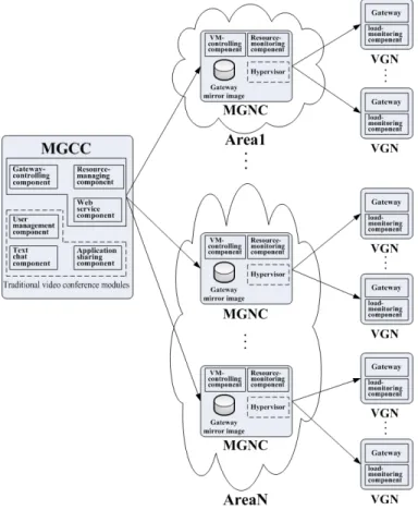
In this section, we describe the integrated structure of the cloud-based multi-gateway system, and list the advantages of the framework. The architecture is designed based on both cloud computing technology and the original architecture model of ADMIRE. We propose the cloud-based architecture for high performance multimedia data processing, which can control a variety of virtual resources based on some physical devices and dynamically configure computing power of the entire cluster. There are three central roles in the proposed architecture: Multi-gateway cloud controller (MGCC), multi-gateway node controller (MGNC) and virtual multi-gateway node (VGN). The architecture is shown in Fig. 1.
Figure 1. Cloud-based video conference multi-gateway system
In addition, there are still some other traditional video conference modules in the same node with the MGCC, and we identify them with dashed box in Fig. 1. These modules implement some basic functions, such as user management, text chat, application sharing, etc, and we no longer make further description about them.
A. Multi-gateway cloud controller
MGCC is an entry-point into the cloud system for users and administrators. It’s the key management module of the platform, which keeps track of cloud resources, makes scheduling decisions, forwards user requests to MGNCs that host user services and maintain user and system related data. Users are only allowed to interact with the MGCC and cannot communicate with any MGNC directly. As a result users have
no information about the node and its configuration on which VMs will run. The MGCC has three main architectural components, which includes: gateway-controlling component, resource-managing component, web service component.
1) Gateway-controlling component
The gateway-controlling component has four key functions.
a) When an user logins, the gateway-controlling
component performs a static load balancing strategy, which uses a hash function to map the user’s public IP address to a multimedia gateway, to assign a reasonable access gateway to the user. The strategy not only shortens the time delay during multimedia data forwarding, but also achieves a balanced distribution of resources.
b) The gateway-controlling component maintains the
information of each multimedia gateway, which includes the existence state and load of each multimedia gateway.
c) The gateway-controlling component could response to
the user migration requests sent by multimedia gateways. During a video conference, multimedia gateways might send user migration requests to the gateway-controlling component due to overload, then the gateway-controlling component migrates part of the users to other normal multimedia gateways.
d) The gateway-controlling component controls the
resources of the entire system by sending resource-controlling commands to the resource-managing component. There are two kinds of resource-controlling commands, one is to create a new virtual gateway node due to more need of data forwarding capability, the other is to merge some of the running virtual gateway nodes due to the existence of more than one low-load multimedia gateways.
2) Resource-managing component
The resource-managing component performs system-wide arbitration of resource allocations and monitors resources. It also processes VM-controlling requests and interacts with MGNCs to effect the allocation and deallocation of physical resources. A simple representation of the system’s resource state (SRS) is maintained through communication with the MGNCs and used in evaluating the realizability of user requests. The SRS tracks the state of resource allocations and is the source of authority of changes to the properties of running reservations. The role of the SRS is executed in a specific situation: when user requests arrive, the information in the SRS is relied upon to make an admission control decision (e.g., VM creation and VM destruction). The MGNC then responds to the control command, processing VM managing operations.
3) Web service component
In addition to the programmatic interface, the framework also offers a web interface for cloud users and administrators, which is implemented by a web service component. Using a Web browser, users can sign up for cloud access, query the system and logon the VM with a special account. Administrators can, additionally, inspect the availability of system resources and the load of each VM, and control the VMs.
B. Multi-gateway node controller
A multi-gateway node controller executes on every node that is designated for hosting VM instances, and each area may comprise more than one MGNCs. An MGNC queries and controls the system software on its node (e.g., the host operating system and the hypervisor) in response to queries and control requests from its MGCC. MGNC obtains list of VM instances and change the state (e.g., starting, running, suspending) of them with the help of VM Hypervisor. Currently, we support VMs that run atop Hyper-v hypervisor, but plan to add support for VMware, Xen, and others in the near future. The MGNC has two central components, which includes: resource-monitoring component and VM-controlling component.
1) Resource-monitoring component
The resource-monitoring component makes queries to
monitor the usage of the node’s physical resources as well as to
learn about the state of VM instances on the node (although a MGNC keeps track of the instances that it controls, instances may be started and stopped through mechanisms beyond
MGNC’s control). The information thus collected is
propagated up to the MGCC in responses to resource describing requests.
2) VM-controlling component
The VM-controlling component executes runInstance, terminateInstance and suspendInstance with the assistance of the hypervisor to respond the VM-controlling command made by MGCC. There are usually three steps during VM creation: (1) copy a VM instance image (the kernel, gateway application and other applications) from local node; (2) configure network of the VM, including IP address allocation and firewall configuration; (3) start a VM instance with the help of the hypervisor. To stop an instance, the VM-control component instructs the hypervisor to terminate the VM, tears down the virtual network endpoint, and cleans up the files associated with the VM.
C. Virtual gateway node
Lots of VGNs, which include multimedia gateways and load-monitoring components, together comprise a huge cluster. The multimedia gateway, which is immobilized on VM instance, has one-to-one relationship with the VM instance. The load-monitoring component monitors the load (CPU usage, available memory, data-receiving rate and data-sending rate) of the node, and regularly sends load information to the gateway-controlling component of MGCC. It also has data-analysis ability, which could calculate the mean and variance recorded in a given length of time, and then compare the calculated value with the threshold set by system. If the calculated value is beyond the threshold, the load-monitoring component will send a user migration request to MGCC.
D. System properties 1) Usability
Some of the system controls and regulation functions, such as the static load-balancing strategy and user migration strategy, are running in an automatic mode so that users can use the same approach with the ordinary video conference software to
interact with others, thus avoiding the complexity of software configuration.
2) Scalability
The MGCC could dynamically change the number of
multimedia gateways to meet users’ data forwarding demand in
real-time. This property not only provides the entire system with a good expansibility, but also reduces energy consumption by merging some low-load multimedia gateways.
3) Reliability
The user migration strategy can successfully solve the reliability problems caused by system shutdown or overload of multimedia gateways, which enhances the reliability of the system.
IV. USER MIGRATION STRATEGY
A good user migration strategy could migrate the users connected to the overloading multimedia gateway to a normally low-load multimedia gateway, which achieves a dynamic load balancing scheme and enhances the reliability of the system.
There are a variety of reasons that cause the multimedia gateway to trigger user migration during a video conference. According to the causes, user migration can be de divided into two kinds: active user migration and passive user migration. In this paper, we design and implement a real-time user migration strategy based on the above mentioned framework, which combines active pattern with passive pattern. Meanwhile, to determine the timing of user migration and to perform the process of user migration are two important links during user migration.
A. The timing of user migration
Active user migration is caused by overloading of multimedia gateways, while passive user migration is triggered by detecting downtime of multimedia gateways. Therefore, it is very important to choose a reasonable overload judgment and downtime-detecting mechanism to ensure the smooth procedure of user migration.
1) Mechanism to determine overload of the multimedia gateway
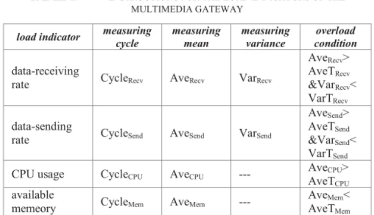
In multi-gateway video conferencing systems, both data-sending rate and data-receiving rate have their certain thresholds due to limitations of the real network, and there will be data loss if the thresholds are exceeded. In addition, normal operations of the multimedia gateway are also affected by VM’s CPU usage and memory usage. Therefore, data-receiving rate, data-sending rate, CPU usage and available memory are selected as the load indicators of the multimedia gateway, and we have done a lot of experiments and data analysis to determine the threshold of each indicator. Instructions for the four indicators are shown in Table 1.
Some descriptions of the indicators in Table 1 are made as follow:
a) The load-monitoring component records the
measurement value of each indicator, and the range of
recording time is set by measuring cycle. For example, if measuring cycle is equal to 5 seconds, we need to record the load indicator values within the last 5 seconds.
b) Measuring mean and measuring variance are
calculated from the actual measuring values of load-monitoring component.
c) Overload conditions are the basis for deciding whether
a load indicator has exceeded its threshold. AveTX and VarTX
are the mean threshold and variance threshold set by system, which are obtained from lots of experiments and data analysis.
VM’s CPU usage and available memory usually change
slowly, whose measurement values experience small fluctuations in a measuring cycle, so their measuring means are enough to decide whether the multimedia gateway has overloaded.
TABLE I. INSTRUCTIONS FOR THE LOAD INDICATORS OF THE MULTIMEDIA GATEWAY
load indicator measuring cycle measuring mean measuring variance condition overload
data-receiving
rate CycleRecv AveRecv VarRecv
AveRecv> AveTRecv &VarRecv< VarTRecv data-sending
rate CycleSend AveSend VarSend
AveSend> AveTSend &VarSend< VarTSend CPU usage CycleCPU AveCPU --- AveAveTCPU>
CPU available
memeory CycleMem AveMem --- AveAveTMem< Mem
2) Downtime-detecting mechanism of the multimedia gateway
ADMIRE video conference system has a TCP-based communication mechanism named Mbus. Each component that wants to use Mbus to interact with others must create a Mbus object, and the Mbus Server is responsible for the maintenance of Mbus objects’ online status. The Mbus server will send “clientdrop” message to the component when it exits. Thus, when multimedia gateways dropped due to downtime or system failures, the gateway-controlling component could quickly detect the dropped multimedia gateways with the assistance of Mbus communication mechanism.
B. User migration process
A good user migration process should ensure the continuity of multimedia data stream as well as minimize the time delay so that clients can receive and play streaming video smoothly. Firstly, we design and implement a kind of regular user migration process based on the communication mechanism between multimedia gateway and MGCC during user login. Then an improved user migration process is proposed and implemented after further analysis of the former one, and this improvement has been proved to be very effective according to a large number of experiments.
The regular user migration process proposed in this paper mainly includes the following seven steps.
Step 1: Triggering migration. In the active user migration, the load-monitoring component of VGN will send control messages containing the overloading reasons to MGCC when it detects one or more load indicators meet the overload condition, then MGCC will execute user migration operations. In the passive user migration, the gateway-controlling component of MGCC will trigger user migration when it detects downtime of a multimedia gateway.
Step 2: Determine the migration objects. First the gateway-controlling component of MGCC analyzes the reasons that lead to user migration, and then choose migration objects. The gateway-controlling component will select all the users as migration objects if the user migration reasons are multimedia gateways dropped, CPU usage overload and available memory overload. While some of the users who send or receive multimedia data will be chosen as migration objects if the user migration reasons are data-receiving overload or data-sending overload.
Step 3: Select the migration target gateway. We prefer to select the normal running multimedia gateway which is in the same area with the migration source gateway as our target; otherwise we will select the system’s default gateway as our target.
Step 4: Record the status information. First of all, the gateway-controlling component records login information of each migration object after determining the migration objects. Then the gateway-controlling component sends migration message to each migration object, and the migration object will execute some state recording operations, which mainly include audio and video transceiver state.
Step 5: Disconnect connections between the multimedia gateway and the migration object. The multimedia gateway should clean up user data during disconnection in this step.
Step 6: Assign a new access gateway for migration objects. The gateway-controlling component assign a new access gateway, selected in step 3, for each migration object according to the information of migration object recorded in step 4. Then the migration target gateway should do some user data generating work to ensure the normal running of the migration objects.
Step 7: Restore the state of the migration object. Gateway-controlling component sends migration-completing message to the migration object, and the migration object will restore audio and video transceiver state according to the information recorded before user migrating and some other information about the new access gateway.
2) Improved user migration process
The improved user migration process is the same with most of the steps of the regular one, which also includes seven steps. The first four steps and the seventh step are the same as the steps of the regular one, where they differ is that the fifth step and the sixth step of the regular one are switched with each other in the improved user migration process. The improved one firstly assigns a new access gateway for migration objects,
and then disconnects connections between the multimedia gateway and the migration object. However, this sample switch may cause a client to have two access gateways within a short period, and the client should send media data to two multimedia gateways or receive media data from two multimedia gateways at the same time, so we need to make some changes on both clients and multimedia gateways to enable them to handle the repeated packets, although the duplicate packets are usually very few. This improved user migration process could reduce the time delay during user migration.
C. The main challenges and their solutions in realizing a user migration strategy
1) Select an appropriate target gateway for the migration objects
There might be more than one low-load multimedia gateways at some point, if a multimedia gateway is randomly selected as a migration target gateway, the migration object and the gateway may be in different areas, which will increase the time delay during data forwarding. In this paper, we add a geographical identification to each multimedia gateway, and prefer to select the low-load multimedia gateway which is in the same area with the migration source gateway as our target gateway, which could reduce the data forwarding delay.
2) Ensure the continuity of multimedia data stream
It is very important to ensure the continuity of multimedia data stream during user migration, which is the key to improve user experience. The strategy proposed in this paper firstly assigns a new access gateway for migration objects, secondly disconnects connections between the multimedia gateway and the migration object, which effectively reduces the time delay in the user migration process, thus ensuring the continuity of the multimedia data stream.
V. EXPERIMENTS AND DATA ANALYSIS A. Determine the thresholds of multimedia gateway’s load
indicators
In this paper, we adopt a unified approach to obtain the original experimental data. We continuously increase one of the system’s load indicators until the multimedia gateway starts to lose packets, then we will record the values of the load indicator within a measuring cycle, and these values are used as our original experimental data, on which we will do a lot of data analysis.
Experiment 1: Determine the measuring cycle
We set up six different bandwidth conditions, do 10 repeated experiments in each condition, and obtain each load indicator’s cycle when the load indicator starts to change radically according to the statistic and analysis for 60 sets of experimental data, as shown in Fig. 2.
With reference to Fig. 2, the measuring cycle of receiving rate is set to 5s, and the measuring cycle of data-sending rate is set to 6s. As CPU usage and available memory both change slowly, we set the measuring cycle of them to 6s according to the experimental observations and experience.
0 5 10 15 20 25 30 35 40 45 50 4 5 6 7 8 9 Ti m es o f o ccurrence
Cycle values when the load indicators begin to change radically(s)
data-receiving rate data-sending rate
Figure 2. Distribution of the measuring cycle
Experiment 2: Determine the thresholds of data-receiving rate’s mean and data-sending rate’s mean
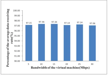
We use the measuring cycle selected in Experiment 1 to intercept each set of experimental data, the length of which is the same as the length of the measuring cycle, and then calculate their means. In order to enhance reliability of the threshold, we select the minimum mean of each bandwidth setting as the basic data to compare with others. Fig. 3 and Fig. 4 show the data comparison results of different bandwidth settings. 97.15 97.36 97.34 97.14 97.24 97.06 90.00 91.00 92.00 93.00 94.00 95.00 96.00 97.00 98.00 99.00 100.00 5 10 15 20 25 30 P er ce n ta ge of th e ave ra ge d at a-re ce iv in g ra te(%)
Bandwidth of the virtual machine(Mbps)
Figure 3. Comparison of data-receiving rate’s means
With reference to Fig. 3, we selected the minimum (97.06%) of various bandwidth settings as the system’s minimum
percentage of the average data-receiving rate (MinRP). Thus we
could get the threshold of data-receiving rate’s mean at
different bandwidth settings by (1).
AveTRecv bw MinRP (1)
bwrepresents the bandwidth of VM.
Similarly, we could get the threshold of data-sending rate’s
mean from Fig. 4.
98.11 98.37 98.24 98.05 98.21 98.01 90.00 91.00 92.00 93.00 94.00 95.00 96.00 97.00 98.00 99.00 100.00 5 10 15 20 25 30 P er ce n ta ge of th e ave ra ge d at a-se n d in g ra te(%)
Bandwidth of the virtual machine(Mbps)
Figure 4. Comparison of data-sending rate’s means
Experiment 3: Determine the thresholds of data-receiving rate’s variance and data-sending rate’s variance
As is identical with Experiment 2, we select the maximum variance of each bandwidth setting as the basic data to compare with others. Fig. 5 and Fig. 6 show the data comparison results of different bandwidth settings.
14.38 27.21 41.83 60.57 73.56 87.14 0.00 10.00 20.00 30.00 40.00 50.00 60.00 70.00 80.00 90.00 100.00 5 10 15 20 25 30 V ar ian ce of d at a-re ce ivi n g r at e
Bandwidth of the virtual machine(Mbps) 2.92
3.75
2.60
2.72
2.57
Figure 5. Comparison of data-receiving rate’s variances
17.78 33.26 55.93 76.37 92.47 108.25 0.00 20.00 40.00 60.00 80.00 100.00 120.00 5 10 15 20 25 30 V ari anc e o f da ta -s endi ng ra te
Bandwidth of the virtual machine(Mbps) 3.10
4.54
4.09
3.22
3.16
The variance reflects data stability in a measuring cycle, and the greater the data-receiving or data-sending rate goes, the larger its volatility becomes. As shown in Fig. 5, with the increasing bandwidth of the virtual machine, the data-receiving rate when packet loss occur increases higher, and its measuring variance becomes larger. Thus we could get the threshold of
data-receiving rate’s variance at a given bandwidth(X) by (2).
Recv
VarT BaseVar X BaseBand 'R (2)
Recv
VarT ,BaseBand , BaseVar, 'R are the threshold of
data-receiving rate’s variance, reference bandwidth, reference
variance and variance increment coefficient. In this article, we select 5Mbps as our reference bandwidth, the maximum variance (14.38) of which is selected as the reference variance, as shown in Fig. 5. The variance increment coefficient varies in different bandwidth range. In order to enhance reliability, we
select the maximum value (3.75) as our system’s variance
increment coefficient, as shown in Fig.5.
Similarly, we get the threshold of data-sending rate’s
variance from Fig. 6.
Experiment 4: Determine the threshold of CPU usage’s mean
We do 10 repeated experiments to determine the threshold of CPU usage’s mean. Fig. 7 shows a comparison of the CPU usage’s mean in each experiment, and we finally choose the minimum CPU usage’s mean (95.86%) as the system threshold of CPU usage’s mean.
97.23 96.52 95.86 96.94 97.76 98.20 95.94 96.41 97.13 96.62 90.00 91.00 92.00 93.00 94.00 95.00 96.00 97.00 98.00 99.00 100.00 1 2 3 4 5 6 7 8 9 10 M ean of CP U u sage (% ) Experiment No.
Figure 7. Comparison of CPU usage’s means
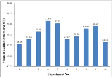
Experiment 5: Determine the threshold of available memory’s mean
We do 10 repeated experiments to determine the threshold of available memory’s mean. Fig. 8 shows a comparison of the available memory’s mean in each experiment, and we select the maximum available memory’s mean (71.59MB) as the system threshold of available memory’s mean.
60.57 62.86 66.52 71.59 70.36 62.87 64.24 67.90 69.20 61.56 50.00 55.00 60.00 65.00 70.00 75.00 80.00 1 2 3 4 5 6 7 8 9 10 M ean of availab le me mor y( M B ) Experiment No.
Figure 8. Comparison of available memory’s means B. User migration experiment
In this paper, the physical environment of the user migration experiment consists of three servers, and two VGNs are deployed on each of them, thus a video conferencing system that includes six multimedia gateways is constituted, on which we do a number of user migration experiments. In the experiments, we record the timestamp of the last packet received by client before user migration and the timestamp of the first packet received by client after user migration, and use the difference of them as the time delay of the user migration.The outcome of the experiment is shown in Fig. 9.
96 102 88 96 94 96 113 101 89 94 99 108 102 96 96 51 56 49 51 51 57 56 56 65 56 57 57 49 49 56 31 46 16 31 28 31 16 31 46 32 31 16 31 32 31 0 10 20 30 40 50 60 70 80 90 100 110 120 1 2 3 4 5 6 7 8 9 10 11 12 13 14 15 Use r migr at io n d elay( ms ) Experiment No. regular migration delay improved migration delay normal delay
Figure 9. Time delay of user migration
The “normal delay” in Fig. 9 refers to the time interval between two packets received by client without user migration. Results can be seen from Fig. 9 that the regular user migration process could control the time delay under 113 milliseconds, which gives users a good experience of audio and video continuity, and the improved user migration process could control the time delay under 65 milliseconds, which gives users a better experience of audio and video continuity. In summary, the user migration strategy implemented in this article can play an outstanding performance in both active pattern and passive pattern, which not only migrate users to the appropriate target multimedia gateway but also ensure the continuity of audio and video during user migration.
VI. CONCLUSION
In this paper, we take full advantage of the outstanding performance of cloud computing, and present a new highly scalable, reliable, and user friendly cloud-based video conference multiple-gateway architecture for the efficient management of large-scale multimedia conferencing service, which can control a variety of virtual gateway resources based on physical devices and dynamically deploy multimedia gateways, thus meeting the needs of system expansion and saving energy by merging some low-load virtual gateway nodes. We also implement a user migration strategy, which combines active pattern with passive pattern, based on the cloud-based video conference multi-gateway system mentioned previously. The strategy can successfully solve the reliability problems caused by overload or downtime, thus improving the quality of service. We have already applied this video conference system with the user migration strategy in many
provinces and cities of China, such as Beijing, Yan’an,
Jinggangshan, Kangbao, etc, and achieved good results. In addition, there are also some disadvantages in this paper. For example, the framework designed in this paper has only one MGCC, whose fault-tolerant mechanism is relatively simple and robustness is relatively weak. In the future, we are planning to do some in-depth studies on these issues.
VII. ACKNOWLEDGEMENTS
This work was supported by the State Key Laboratory of Software Development Environment Funding No.SKLSDE-2012ZX-19.
REFERENCES
[1] Rajkumar Buyya, Chee Shin Yeo, “Market-oriented cloud computing:Vision, hype, and reality for delivering it services as computing utilities,” Proceedings of 10th IEEE Int. Conf. High Performance Computing and Communications. 2008:5–13.
[2] A. Weiss, “Computing in the Clouds,” NetWorker, 2007, 11(4):16-25. [3] R. Buyya, C.S. Yeo, S. Venugopal, J. Broberg, and I. Brandic, “Cloud
Computing and emerging IT platforms: Vision, hype, and reality for delivering IT services as the 5th utility,” Future Generation of Computer Systems, 25 (2009), 599-616.
[4] Ling Qian, Zhiguo Luo, Yujian Du, and Leitao Guo, “Cloud Computing: An Overview,” Cloud Computing, Vol. 593112009, 626- 631.
[5] Yang zhenZou, Changjia Chen, “MCU System Software in Video Conference Network,” IEEE Communication Transations, 1996: 65- 68. [6] M. Barnes, C. Boulton, and O. Levin, “A Framework for Centralized
Conferencing,” RFC 5239, IETF, June 2008.
[7] Y.Cho, M. Jeong, J. Nah, W.Lee and J.Park, “Policy-Based Distributed Management Architecture for Large-Scale Enterprise Conferencing Service Using SIP,” IEEE Journal on Selected Areas in Communications. 2005: 1934-1949.
[8] Y. Cho, M. Jeong, J. Park, and W. Lee, “Distributed Management
Architecture for Multimedia Conferencing Using SIP,” Proceedings of the First International Conference on Distributed Frameworks for Multimedia Applications. 2005: 98-105.
[9] A. Buono, S. Loreto, L. Miniero, and S. P. Romano, “A Distributed IMS Enabled Conferencing Architecture on Top of a Standard Centralized Conferencing Framework,” IEEE Communications Magazine. 2007: 152-159.
[10] Z. Yang, H. Ma and J. Zhang, “A Dynamic Scalable Service Model for SIP-based Video Conference,” Proceedings of the Ninth International Conference on Computer Supported Cooperative Work in Design. 2005: 594-599.
[11] JinTian, Xiangzhi Sheng, LuJian, “Admire - A Prototype of Large Scale E-collaboration Platform,” Grid and Cooperative Computing, Second International Workshop. 2003: 335-343