Flexible SOA Lifecycle on the Cloud using SCA
Cristian Ruz, Franc¸oise Baude, Bastien Sauvan INRIA Sophia Antipolis M´editerran´ee CNRS, I3S, Universit´e de Nice Sophia Antipolis
France
{First.Last}@inria.fr
Adrian Mos, Alain Boulze INRIA Rhˆone Alpes
Grenoble France
{First.Last}@inria.fr
Abstract—We present an integrated approach to design, monitor and manage the lifecycle of applications based on the Service Oriented Architecture (SOA) principles and capable of taking advantage of cloud computing environments. The integrated framework takes profit of publicly available open source tools and standards in an effective and coherent way, and covers the steps from business and architectural design of the application, to deployment and runtime support. We exemplify our approach with a walkthrough in a simple yet illustrative scenario.
Keywords-Service Oriented Architecture, SCA, Design, Mon-itoring, Cloud Computing
I. INTRODUCTION
As identified in the “Hype Cycle for Emerging Technolo-gies 2009” [1], Cloud Computing technoloTechnolo-gies will reach in two to five years the “plateau” of mainstream adoption. As enterprises seek to consume their IT services in the most cost-effective way, interest is growing for using a broad range of infrastructure services such as computational and storage resources from ’the cloud’ or even from multiple and heterogeneous clouds at once, rather than from on-premises equipments. Of course, the aim is to still run and possibly dynamically configure and adapt legacy business applications within such virtualised environments.
The ability to exploit cloud environments raises several challenges, see [2]. Indeed, relying on cloud technologies further abstracts away from concrete and effective manage-ment tasks like resource provisioning, deploymanage-ment, moni-toring, management and performance optimizations. This is good for end-users but it is more demanding for the supporting tools which must still offer end-users an abstract and multi-perspectives view [3] of the application while giving them the ability to control it.
Emerging solutions can harness one or multiple clouds, and tackle different concerns of the lifecycle, like (1) dynamic resource provisioning and service packaging-deployment (e.g. [4], [5]); (2) SLA monitoring and enforce-ment e.g. [6]. Few research explicitly aims at providing an integrated framework allowing the user to act upon the whole lifecycle of the SOA application in the cloud (e.g. [7]), and none allows the user to act upon this lifecycle through a design-oriented view only, yet including QoS
related considerations, which is our goal. To achieve this vision is not easy, as there is a lack of coordination and intermanageability among the available solutions addressing the different steps of the lifecycle management (resource provisioning, packaging and deployment of the software bricks, monitoring, application reconfiguration, etc).
In this paper we propose an integrated and open frame-work for supporting flexible service management over the cloud, by leveraging the principles of SOA. Our approach relies on a coherent design and monitoring at each level and has been implemented using various standards (e.g. BPMN, SCA) and technologies of the business and infrastructure layers, and fits a cloud environment.
II. INTEGRATED FRAMEWORK
The integrated framework we propose takes into consider-ation all levels of SOA development [8]. We have identified the following required capabilities:
• Tooling support to define business processes definitions
and architectural specifications.
• Synchronization between business process definitions
and architectural specifications.
• Support to express quality-of-service (QoS) constraints and automatic generation of deployment artifacts that include the required QoS information.
• Constant multi-level monitoring of the execution envi-ronment and tooling support for extracting monitoring information and updating design artifacts appropriately.
• Ability to modify the runtime configuration in order to ensure optimal execution.
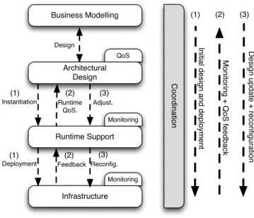
The components of the framework are separated in a vertical approach, tackling the requirements to manage the SOA lifeycle from business modelling to the runtime infras-tructure. See 1.
The business model of the application is the starting point for the SOA lifecycle. In the initial design phase (Fig. 1 (1)), the business model is converted to an equiv-alent architectural description. The architectural description, possibly improved, is translated to an appropriate runtime support, which deploys and instantiates the application on the infrastructure.
Business Modelling Runtime Support Monitoring C o o rd in a tio n Infrastructure QoS In itia l d e si g n a n d d e p lo yme n t Deployment Instantiation Reconfig. Runtime QoS. Feedback Adjust. Mo n ito ri n g + Q o S fe e d b a ck D e si g n u p d a te + re co n fig u ra tio n Monitoring Architectural Design Design (1) (2) (3) (1) (1) (2) (2) (3) (3)
Figure 1. Framework elements
At each level, monitoring artifacts are added to be able to extract meaningful monitoring information at runtime (Fig. 1 (2)). The goal is to provide feedback from the infrastructure level to the runtime and architectural design levels, allowing the manager of the application to obtain a QoS characterization. The information at each level can be used by the person in charge of that level (i.e. system ad-ministrator, SOA application designer, etc) to take decisions in order to improve the performance of the application from its particular point of view, f.e., modifying the allocation of nodes (runtime level), or modifying the composition of the application (design level). However, in our proposition we also claim that the decision taking can be improved if we provide synthetic (preferably to exhaustive) monitoring information to the design level, so that the manager of the SOA application can consider the information collected from all levels to take a better decision.
The decisions taken translate in changes either in the design itself, or in the associated deployment, which may so require areconfiguration phase(Fig. 1 (3)). In this phase, the design decisions are thus propagated to the appropriate level, keeping a consistent view. After this step, the monitoring phase now provides QoS characterization from the updated infrastructure. Through these phases it is possible to obtain a continuous lifecycle management of the application.
To achieve this general working, this paper describes our solution which allows the various levels to meaningfully interact.
The interaction between the components of the frame-work is coordinated by the use of an SOA metamodel. The specific representations used at each level are con-verted to and from this metamodel in order to provide an effective two-way communication among the actual tools
BPMN Editor GCM Runtime BEP Monitoring Ma n g ro ve C o re (SO A me ta mo d e l) Infrastructure QoS GCM Monitoring
SCA Editor + extensions
Figure 2. Tooling support implementing the framework. SOA Editors are connected with the Runtime Support and Monitoring through the SOA metamodel
composing the framework and keeping a coherent, always-in-sync representation at the different levels. The use of the metamodel provides flexibility to the framework as new tools and runtime platforms can be added by programming the required transformations, giving a broader range of options for SOA management.
III. TOOLING ANDRUNTIMESUPPORT
We present the tooling and runtime support that we have used in the implementation of our framework for flexible SOA lifecycle management in the cloud.
A. Tooling Landscape
In the context of SOA, the Eclipse Foundation offers open-source tools for a variety of purposes ranging from software development to architecture design to business process definition. In particular the Eclipse SOA top-level project [9] provides editing tools like the BPMN Modeler [10], the SCA Tools Editor [11] and the Mangrove SOA Modeling Framework [12].
The BPMN Modeler [10] is a business process diagram editor for business analysts implementing the BPMN speci-fications. TheSCA Toolsproject [11] is a toolset for design-ing SCA composites [13], includdesign-ing code generation and deployment support for several SCA runtimes. Both editors provide extension capabilities that are leveraged through the use of the Mangrove integration project. TheMangrove SOA Modeling Framework[12] serves as a central Eclipse SOA modeling container useful for existing and upcoming SOA editors and runtime platforms. Mangrove employs a simple and extendable SOA metamodel as its core, providing a
consistent, always-in-sync representation of common SOA artifacts.
The core SOA metamodel used in Mangrove is based on the Eclipse Modeling Framework (EMF) [14] and it contains the SOA elements and their inter-relations, enabling the storing of “distilled” SOA elements used by different editors and tools. The use of EMF facilitates the bidirectional transformations between Eclipse editors and tools and the Mangrove core as the vast majority of Eclipse projects use EMF. Besides contributing to the actual Mangrove core, we have created a collection of Mangrove plugins for bi-directional conversions between the core and the SCA Edi-tor, between the editor and the GCM/Proactive runtime, as well as for updating the editors with monitoring information. B. Runtime Support
The runtime support for the application is based on the GCM/ProActive middleware. GCM/ProActive is the imple-mentation of the Grid Component Model (GCM) [15] over the ProActive grid/cloud middleware [16], which provides a programming model based on asynchronous active objects and futures. GCM is an extension of the Fractal component model [17], that includes the notion of collective multi-cast/gathercast interfaces, and the notion of Virtual Nodes (VN) as an abstraction for the deployment of distributed applications.
The VN abstraction is used to refer to the location where the GCM components will be deployed without actually specifying a physical node, and delaying this association to the moment when the actual resources are available. The VN abstraction allows to separate the deployment concerns from the actual resources. The ProActive Scheduler [16] is an application that allows to manage tasks over distributed resources and can gather and relinquish nodes launched on desktop computers, clusters, grid or cloud environments, while also allowing to monitor their state. Dynamic node provisioning is thus enacted through this manager.
For monitoring purposes, GCM components provide a monitoring interface that allows an external application to connect to any GCM component and obtain QoS values, as well as to insert customized probes for reporting metric values [18].
Runtime management of the application is possible using PAGCMScript, an extension of FScript [19], that can be used for reconfiguring and introspecting GCM-based com-ponent architectures, possibly instantiating new comcom-ponents on (new) VNs. GCM components expose an interface for receiving PAGCMScript commands and execute them using an embedded PAGCMScript engine.
IV. TOOLING ANDRUNTIMEINTEGRATION
The tooling elements and the runtime support are used in the continuous loop of the framework, realizing our
integrated approach for a flexible SOA lifecycle management in the cloud.
Figure 2 shows the elements described, and their role by comparison to Figure 1. The solid arrows indicate the actual connections and communication direction between the elements of the framework and the Mangrove Core, which are implemented as transformation plug-ins, as well as the collection of monitoring data from the infrastructure level into the GCM runtime support. The dashed lines indicate the conceptual relationships that are obtained as a result of the interactions of the different elements of the framework.
A. Initial design and deployment phases
Starting from the BPMN editor, a BPMN diagram spec-ifying the business process definition of the application is converted to an SCA diagram, and an initial architectural view is obtained in the SCA Editor. This process relies on the intermediate representation used by the Mangrove Core and provides a basic equivalent SCA view. Using the SCA editor, the designer of the application may adjust the architecture, for example, by introducing additional components or defin-ing external dependencies, refindefin-ing the architecture. These modifications are reflected in the intermediate representation of Mangrove.
Using the SCA Editor and a plugable extension to this editor, the SCA diagram is augmented with VN names. This is a required extension, as the notion of nodes and deployment are not part of the SCA specification. The association that we introduce at this point, allows to establish a relationship SCA↔VN. From this augmented description, an equivalent GCM ADL1 descriptor can be generated.
The GCM ADL descriptor contains the GCM components obtained from the original SCA description, their bindings, and the VNs where they will be deployed, thus offering a vision obtained directly from the architectural design, and at the same time closer to infrastructure concerns. The GCM ADL description, moreover, provides a model where monitoring and reconfiguration capabilities can be added to the components, which will be important at runtime.
At deployment time, the Scheduler is requested to pro-vision the actual nodes where the components will be deployed, so establishing the relationship VN↔nodes. This relationship becomes available through the GCM monitoring interface. Both relationships are a key step to ensure the correct propagation of monitoring data from the application and the infrastructure, to the appropriate representation in the editors. They also allow to separate the deployment requirements (which are known to the designer of the application), from the actual available resources (which are known to a system administrator).
B. Monitoring Feedback phase
The GCM description obtained allows to introduce mon-itoring concerns in the components. Being used as an intermediate layer between design and infrastructure, the monitoring interface of GCM components allows to insert sensors that can measure QoS metrics related to the in-teraction between the components (f.e., response time of requests), and also related to infrastructure details (f.e., CPU load, free memory).
The SCA Editor can receive and display monitoring information obtained from the runtime through the use of specialized plug-ins extracting data from the monitoring sensors that communicate their measurements to a central-ized Basic Event Processor (BEP). The BEP performs basic data processing operations such as storing and aggregating events, and query operations. Note that the description of the BEP is out of the scope of this paper.
Concretely, the monitoring interface of GCM components is used by the BEP to collect data about the application and about the infrastructure. This monitored data plus the relationships SCA↔VN and VN↔nodes are inserted in the Mangrove intermediate model, from which they can be represented back in the SCA Editor, thus offering an integrated runtime view of the deployed application. C. Design modification and reconfiguration
From the integrated view, and based on the monitoring feedback information, an administrator can decide to make a modification on the application. These modifications may in-clude architectural changes like the modification of bindings or the addition of new SCA components; or changes related to the infrastructure like the migration of a component to another infrastructure, f.e., by changing the VN associated to a component.
Once a modification is decided in the editor, it must be reflected in the deployed application. This is achieved by executing reconfigurations on the running application. As previously mentioned, GCM components expose a recon-figuration interface that allows to execute PAGCMScript commands that describe reconfiguration actions.
D. Framework Summary
The integration of the different phases allows us to provide most of the capabilities outlined in Section II:
• In the Initial Design and Deployment phase, the Busi-ness Modelling tool (in this case, the BPMN Editor) and the Architectural Design tool (in this case the SCA Editor), allow to describe the business process definitions and the architectural specifications.
• Using the intermediate representation, in this case,
the representation in the Mangrove Core, the SCA view is obtained in a coherent way from the BPMN specification. U se r Email Brochure Service T ra ve l Se rvi ce Get Weather Get Hotel Rec. Create Brochure Send Email
Figure 3. BPMN diagram of the Travel Service.
• The GCM runtime supports the dynamic insertion of
monitoring elements that are able to check QoS con-straints. Using this, a given constraint expressed at the design level in the SCA Editor can be reflected into a runtime constraint that can be checked in the GCM components. However, the actual insertion process re-lies on predefined elements to perform the constraint checking instead of automatically generated ones.
• The integration of the GCM monitoring interfaces, the BEP monitoring support, and the Mangrove Core repre-sentation allows to monitor each level of the application and surmount the monitoring information collected to a synthesized view on the SCA Editor.
• The dynamic reconfiguration capability of GCM com-ponents and their integration with the Mangrove Core representation allows to reflect modifications described on the upper levels in a dynamic way.
V. SCENARIO-BASEDWALKTHROUGH
We illustrate our integrated approach for managing the lifecycle of an SOA-based application with a scenario that follows the steps from the business and architectural design of the application to the deployment and runtime infrastruc-ture, then obtaining back the runtime details on the design view, and finally triggering adaptations from the design level to the infrastructure level.
A. Scenario description
The scenario represents a travel service. In this context, a customer requests information about a travel destination, and the application works to provide updated information about the weather and proposed hotel acommodations according to the customer budget in a brochure in PDF format, which is sent via email. The weather and hotel information are obtained via external services, and the customized brochure composition process is run as part of the service in a cloud infrastructure. Once the customer chooses his prefer-ences, (destination, budget range, email address) the service collects the information, starts the brochure composition request, and upon finishing the process, an email server is contacted to send the finalized brochure.
B. Design and Deployment Phase
The business analyst uses the BPMN editor to create the description of the process, in Figure 3, from which the
Travel Composite Travel Service Brochure Composer Email Brochure Service SMTP Server Weather Service Hotel Rec. Service
Figure 4. Initial SCA view of the Travel Service
Travel Composite Travel Service Brochure Composer Brochure Composer Weather WS Hotel Recom. WS SMTP Server Email Brochure Service
Figure 5. SCA view for the design phase.
Mangrove transformation creates a basic SCA description, shown in Figure 4. The architecture designer modifies this description by defining the Weather, Hotel, and Mail service components as external services. Notice that these modi-fications, although reflected in the Mangrove intermediate model, do not need to be reflected in the BPMN descrip-tion as they do not change the business definidescrip-tion of the application.
The designer defines the implementation and protocols to be used by the SCA components. In this example, the Travel Service component is associated to a BPEL orchestration; the Brochure Composer is assigned to a Java library. The Brochure Composer is made dependent on the Mail service, as the Java library is capable to communicate with the Mail interface. Finally, the designer adds a second Brochure Composer in order to balance the request load between them. This load balance behaviour must be provided by the Travel Service component. The obtained design is shown in Figure 5.
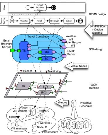
Using the SCA editor, each SCA component is associated with a VN, introducing deployment concerns in the lifecycle for the first time. The “Travel Composite” and the “Travel Service” components are associated to VN manager and each “Brochure Composer” is associated respectively to VNs workers-1 andworkers-2 (Fig. 6).
From the SCA+VN description, a GCM ADL descriptor is generated containing the equivalent description expressed in the GCM model (Fig. 6). Using the GCM ADL descriptor, the Scheduler is called to obtain a set of physical nodes and associate them with the declared VNs (Fig. 7).
A holistic view of the relationship between design, run-time, and infrastructure levels is shown in Figure 8,
con-Travel Service Travel Composite Brochure Composer 1 Brochure Composer 2 Weather WS Hotel Recom. WS SMTP Server Monitoring Email Brochure Service {VN:workers-1} {VN:workers-2} {VN:manager} {VN:manager} Reconfiguration
Figure 6. GCM view of the Travel Service example with annotated VNs
Node: A Node: B Node: C VN: manager VN: workers-2 VN: workers-1
Figure 7. Instantiation on nodes obtained from the ProActive Scheduler. VNs are indicated by dashed lines.
Travel Composite TS BC BC Weather WS Hotel Recom. WS SMTP Server Email Brochure Service TS BC1 BC2 Monitoring Node: A Node: B Node: C VN: manager VN: workers-2 Reconf. + Virtual Nodes +Nodes ProActive Scheduler VN: workers-1 BPMN2SCA + Design customiz. SCA design BPMN design GCM Runtime Infrastructure Node: D U se r Email Brochure Service T ra ve l Se rvi c
e Weather Hotel Brochuer Email
Figure 8. From design to deployment
cretizing the interactions presented in Figure 2. C. Monitoring Phase
The monitoring infrastructure is added as the application is deployed and it is available through the GCM Monitoring
interfaces. In this case, the monitoring infrastructure at the level of the GCM components consists of event listeners in each GCM component that detect the interaction between the components and provide an “Average Respone Time” metric; and also include sensors in each GCM component that report the CPU load and hostname of the node where the component is running. These values are exposed through the monitoring interface of each GCM component.
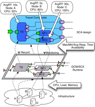
The BEP engine retrieves the monitoring information from the monitoring interfaces of the GCM component and allows the Mangrove core to associate runtime metrics (response time), deployment details (physical nodes used), and infrastructure data (CPU utilization) to each SCA com-ponent in the design view. The relationship between GCM components, VNs and physical nodes can thus be retrieved and the BEP engine can identify the source of the monitored QoS metrics at each level, and update them in the SOA metamodel so that they properly updated in the SCA Editor. The manager of the application obtains the QoS values for each SCA component in accordance to the infrastructure. This relationship is shown in Figure 9.
D. Reconfiguration Phase
From the integrated view of design and monitored in-formation, the manager of the application can see that the component “BC2” is taking too much time to create the file, while “BC1” takes much less time with a lower CPU load. This problem may be caused, for instance, by a high demand of requests provoking contention on the composer, or because the node “C” has limited computing power for composing a PDF file.
The manager decides to migrate “BC2” to another node to solve the problem, and changes the VN relationship for “BC2” in the SCA Editor for a VN calledworkers-hpVN, which hosts nodes with better capabilities. Upon acknowl-edging the modification, a PAGCMScript script is executed that executes the migration. The migration of a component implies stopping the component “BC2”, obtaining a new node from the Scheduler for the workers-hp VN, execute the migration from the old node to the new one, updating the bindings of “BC2” and finally restarting the component “BC2”.
The script makes a request to the Scheduler to provide a new node and, once the new node D is obtained, it migrates the component and restarts it in node D.
Note that we are not strictly defining how the PAGCM-Script is constructed: it may be a custom script written by the designer of the application, a predefined template script complemented with the editor, or automatically generated from the differences in the previous and the current designs. Figure 10 shows the modifications from the design level to the infrastructure level. The old node C is not part of the used infrastructure anymore and could be relinquished through the Scheduler. The infrastructure changes are backpropagated
Travel Composite TS BC2 BC1 TS BC1 BC2 Monitoring A B C Reconf.
CPU, Load, Memory Max/Min/Avg Resp. Time
Availability AvgRT: 5s. Node: B CPU: 80% AvgRT: 10s. Node: A CPU: 20% AvgRT: 30s. Node: C CPU: 100% GCM/SCA Runtime SCA design Infrastructure D
Figure 9. Monitoring from infrastructure to design
Travel Composite TS BC2 BC1 TS BC1 BC2 Monitoring A B Reconf. "Migrate to 'workers-hp'" GCM/SCA Runtime SCA design Infrastructure Trigger GCMScript on associated component
Request new node + propagate modifications D D C VN: workers-hp VN: workers-2 VN: workers-1 VN: manager
Figure 10. Reconfiguration reflected in infrastructure change.
upwards, so that the monitoring framework now reports the QoS values from the new node and the SCA design view is correctly updated.
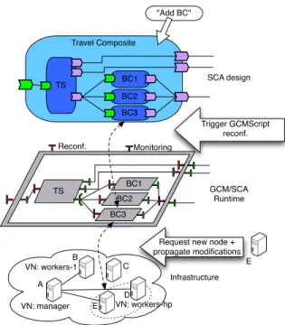
The manager of the application, now receiving the QoS values for the updated infrastructure, and wanting to profit of the new infrastructure, decides to add a third “Brochure Composer”. The manager modifies the design and adds a new “BC3” component associating it with the high per-forming workers-hpVN. The modification is propagated to
Travel Composite TS BC3 BC1 TS BC1 BC3 Monitoring A B Reconf. "Add BC" GCM/SCA Runtime SCA design Infrastructure Trigger GCMScript reconf.
Request new node + propagate modifications D E BC2 BC2 C VN: workers-1 VN: workers-hp VN: manager E
Figure 11. Design modification reflected in infrastructure change
the GCM ADL description and enacted through a PAGCM-Script. The script ask the Scheduler to obtain a new node from the workers-hp VN which, depending on the con-figuration of the VN, can include one or more nodes. Assuming that a different node, called “E” is obtained, then the script deploys the component “BC3”, creates the appropriate bindings, and starts it. The modifications made in the design level are now reflected in the infrastructure level, and the monitoring information obtained in the editors is now consistent with the new infrastructure, as shown in Figure 11.
VI. CONCLUSIONS ANDPERSPECTIVES
In this work we have described an integrated approach for managing the lifecycle of SOA-based applications using an SCA design model integrated with runtime and infrastructure concerns, and that can be deployed in a cloud environment. The approach takes profit of public available open source tools and standards and integrates them in a coherent way from the design to the deployment steps, providing moni-toring and management capabilities at runtime in all layers. This work concretizes the approach presented in [8] and can be extended to incorporate additional features of the SOA model. Most of the current tooling is already available for implementing the described integrated approach.
Starting from this integration basis, the next steps are to improve, i.e., to better automate and generalise the expres-sion of crosscutting concerns in deployement, monitoring and management. In particular, we plan to improve the re-sources acquisition process by allowing to describe complex requirements and guide the provision of nodes from the
Resource Manager to the real needs of the application. For example, specifying requisites like “Obtain a node withX%
availability,Y-core CPU and a cost of no more than $Z per hour”.
Another remaining step is to properly incorporate the description of SLA requirements in the initial and recon-figuration phases, and use the monitoring features to trigger predefined actions for notification or prevention, that can be needed to enforce compliance to an SLA. This step requires a proper means to translate constraint that may be described already in the business process level and to map them to a design element in the architectural specification. Once the design element is associated to a concrete constraint, we plan to use the dynamic capabilities of GCM components to insert elements that are able to check these constraints.
REFERENCES
[1] Gartner Inc., “Gartner’s hype cycle special report for 2009,” http://www.gartner.com/it/page.jsp?id=1124212, July 2009. [2] K. Sripanidkulchai, S. Sahu, Y. Ruan, A. Shaikh, and C.
Do-rai, “Are clouds ready for large distributed applications?”
SIGOPS Oper. Syst. Rev., vol. 44, no. 2, pp. 18–23, 2010. [3] R. Schmidt, “Perspectives for moving business processes into
the cloud,” inBPMDS 2010 and EMMSAD 2010, ser. LNBIP, pp. 49–61.
[4] R. Mietzner, T. Unger, and F. Leymann, “Cafe: A generic configurable customizable composite cloud application frame-work,” inOTM 2009, ser. LNCS, 2009, vol. 5870.
[5] W.-T. Tsai, X. Sun, and J. Balasooriya, “Service-oriented cloud computing architecture,”3rd Intl. Conf. on Information Technology: New Generations, 2010.
[6] A. Chazalet, “Service level checking in the cloud computing context,” in3rd Int. Conf. on Cloud Computing, 2010. [7] C. Chapman, W. Emmerich, F. Marquez, S. Clayman, and
A. Galis, “Software architecture definition for on-demand cloud provisioning,” inHPDC’10. ACM, pp. 61–72. [8] A. Mos, A. Boulze, S. Quaireau, and C. Meynier,
“Multi-layer perspectives and spaces in SOA,” in2nd Intl. Workshop on Syst. Development in SOA environments, 2008.
[9] “Eclipse SOA Project,” http://www.eclipse.org/soa/. [10] “Eclipse BPMN,” http://www.eclipse.org/bpmn/. [11] “Eclipse SCA Tools,” http://www.eclipse.org/stp/sca/. [12] “Eclipse Mangrove,” http://www.eclipse.org/mangrove/.
[13] “Service Component Architecture
Spec-ifications,” http://www.osoa.org/display/
Main/Service+Component+Architecture+Specifications, March 2007.
[15] F. Baude, D. Caromel, C. Dalmasso, M. Danelutto, V. Getov, L. Henrio, and C. P´erez, “GCM: A Grid Extension to Fractal for Autonomous Distributed Components,”Annals of Telecommunications, vol. 64, no. 1, pp. 5–24, 2009. [16] “Proactive Parallel Suite,” http://proactive.inria.fr.
[17] E. Bruneton, T. Coupaye, M. Leclercq, V. Qu´ema, and J.-B. Stefani, “The FRACTAL component model and its support in Java: Experiences with Auto-adaptive and Reconfigurable Systems,”Softw. Pract. Exper., vol. 36, no. 11-12, pp. 1257– 1284, 2006.
[18] C. Ruz, F. Baude, and B. Sauvan, “Component-based generic approach for reconfigurable management of component-based soa applications,” in Proceedings of the 3rd International Workshop on Monitoring, Adaptation and Beyond, ser. MONA ’10. New York, NY, USA: ACM, 2010, pp. 25–32. [Online]. Available: http://doi.acm.org/10.1145/1929566.1929570
[19] P.-C. David, T. Ledoux, M. L´eger, and T. Coupaye, “FPath and FScript: Language support for navigation and reliable reconfiguration of Fractal architectures,”Annals of Telecom-munications, vol. 64, pp. 45–63, 2009.