Instruction Pamphlet
September 18, 2013IP-175
ISSUE NO. 6(Supersedes S-4014)
REPAIR TRACK
MAINTENANCE
OF DB-60 TYPE
FREIGHT BRAKE
EQUIPMENT
748 Starbuck Ave. Watertown, NY 13601
Table of Contents
Section Page
1.0 General Information ... 6
2.0 Safety Precautions ... 6
3.0 General Requirements ... 7
4.0 Procedure for Testing DB-60 Type Freight Brakes on Repair Tracks... 7
5.0 Procedures for Cleaning, Disassembling and Assembling of ... 8
DB-60 Type Freight Brakes on Repair Tracks 5.1 DB-10 Service Portion ... 8
5.2 DB-20 and DB-20L Emergency Portion ... 18
5.3 Body Mounted Cylinders ... 21
5.4 Truck Mounted Cylinders ... 23
5.4.1 NYCOPAC Assembly - With handbrake ... 23
5.4.2 NYCOPAC II Assembly - With handbrake (Truck Set) ... 28
5.4.3 NYCOPAC IIA Assembly - With handbrake (Truck Set) ... 31
5.4.4 TMB-60 Truck Mounted Brake System - With handbrake ... 34
5.5 Vent Valve ... 37
5.6 Angle Cock ... 39
5.7 End Cock……… .. 40
5.8 Dirt Collector Cut-Out Cock ... 41
5.9 Retaining valve ... 43
5.10 KRD2A-500AR Slack Adjuster ... 45
5.10.7 Adjustment ... 45
5.11 KRD-482-E Slack Adjuster ... 49
5.11.7 Adjustment ... 49
5.12 EL-60 Empty Load Valve Portion ... 53
5.12.10 Inspection ... 54
5.12.11 Adjustment ... 54
Table of Contents (cont…)
5.14 ELRP Load Proportional Valve ... 60
5.15 S-1 Sensor Valve ... 62
5.15.10 Inspection ... 63
5.15.11 Adjustment ... 63
5.16 P-1 Load Proportional Valve ... 64
6.0 Rubber Parts, Shelf Life and Storage ... 66
REVISION PAGE
DECEMBER 12, 2003 Original Issue.
ISSUE NO. 1
DECEMBER 4, 2004 Added Chapter 5, Sections 4 through 10.
ISSUE NO. 2
JUNE 18, 2007 Added Chapter 5, Sections 7, and 11 through 15.
ISSUE NO. 3 Updated Figures 33, 34, 35.
Added Figure 9.
Added notes to sections 5.3.9 & 5.3.13.
Added sections: 4.9, 4.12, 5.4.3.17, 5.5.9, 5.8.9, 5.9.9. Added torque value table to section 7.9.
Removed 5.1.22.
FEBRUARY 27, 2008 Added section 5.11 KRD-482-E Slack Adjuster
ISSUE NO. 4
AUGUST 8, 2010 Update illustrations on pages 47, 48, 51, and 52. ISSUE NO. 5
SEPTEMBER 18, 2013 Added orientation note to Section 5.5, before test Section 5.5.10.
List of Illustrations
Illustration Title Page
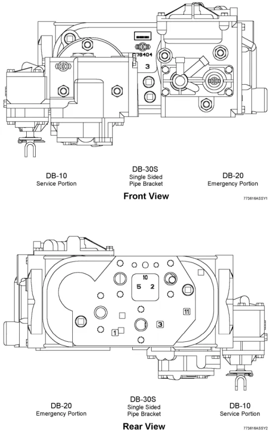
Fig. 1 DB-60 Control Valve Operating Portions and Standard Pipe Bracket ... 10
Fig. 2 DB-60L Control Valve Operating Portions and Standard Pipe Bracket ... 11
Fig. 3 DB-60 Control Valve Operating Portions and Single Sided Pipe Bracket ... 12
Fig. 4 Shipping Parts ... 13
Fig. 5 Control Valve Portions with Shipping Parts ... 14
Fig. 6 Service Portion Strainer Nut Wrench ... 15
Fig 7 Strainer Nut for Brackets Without Access Receiver Plates ... 16
Fig. 8 Strainer Nut for Brackets With Access Receiver Plates ... 16
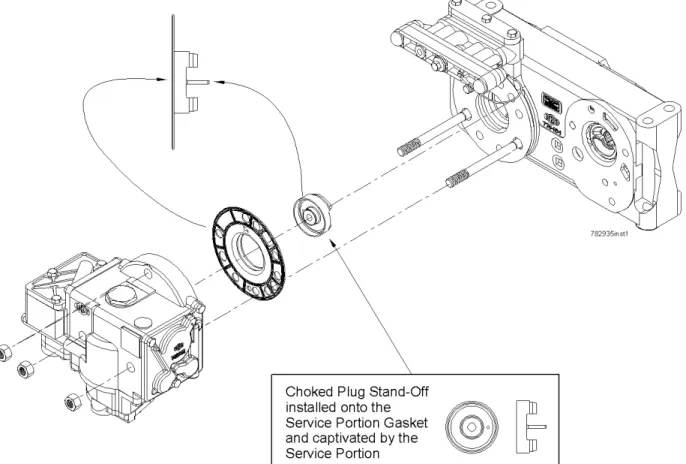
Fig. 9 Choked Plug Stand-Off ... 17
Fig. 10 Emergency Portion Strainer Nut Wrench ... 19
Fig. 11 Instructions for DB-20 and DB-20L Emergency Portion Identification ... 20
Fig. 12 Push Rod Connection ... 22
Fig. 13 Brake Cylinder Non-Pressure Heads ... 22
Fig. 14 Push Rod Holder and Locking Nut ... 25
Fig. 15 NYCOPAC Assembly - With Handbrake ... 25
Fig. 16 Spacing Block and Hanger Dimensions ... 26
Fig. 17 Spacing Block Placement ... 26
Fig. 18 NYCOPAC Hand Brake Adjustment ... 27
Fig. 19 NYCOPAC II Assembly - With Handbrake (Truck Set) ... 30
Fig. 20 NYCOPAC IIA Assembly - With Handbrake (Truck Set) ... 33
Fig. 21 TMB-60 Truck Mounted Brake System - With Handbrake ... 36
Fig. 22 KM-2 Vent Valve ... 38
Fig. 23 No. 8 Vent Valve ... 38
Fig. 24 Standard and Flanged Gripseal Angle Cocks ... 39
List of Illustrations (cont…)
Illustration Title Page
Fig. 26 Dirt Collector Cut-Out Cock ... 42
Fig. 27 Composite Three Position retaining Valve ... 44
Fig. 28 NY-3 Three Position Retaining Valve ... 44
Fig. 29 KRD2A-500AR Slack Adjuster ... 46
Fig. 30 Center Rod Slack Adjuster Installation ... 47
Fig. 31 Top Rod Slack Adjuster Installation ... 48
Fig. 32 KRD-482-E Slack Adjuster ... 50
Fig. 33 Center Rod Slack Adjuster Installation ... 51
Fig. 34 Top Rod Slack Adjuster Installation ... 52
Fig. 35 EL-60 Empty Load Valve Portion ... 53
Fig. 36 ELRP Sensor Valve ... 57
Fig. 37 ELRP Load Proportional Valve ... 61
Fig. 38 S-1 Sensor Valve ... 62
Fig. 39 P-1 Load Proportional Valve ... 65
Fig. 40 Port Identification Standard Pipe Bracket (Emergency Portion Face) ... 68
Fig. 41 Port Identification Standard Pipe Bracket (Service Portion Face) ... 69
Fig. 42 Port Identification Single Sided Pipe Bracket (Portion Face) ... 70
1.0 GENERAL
INFORMATION
This manual covers procedures for cleaning and testing of KNORR Freight Brake Equipment Components on repair tracks.
2.0 SAFETY
PRECAUTIONS
2.1 Observe all Railroad rules and regulations. Whenever there is a conflict between the instructions given in this manual, the Railroads rules and regulations will govern.
2.2 When performing any test work on devices or equipment while they are on the vehicle (Single car test, etc.) special precautions must be taken to ensure that vehicle movement will not occur which could result in injury to personnel and/or damage to equipment. Make sure the hand brake is applied and that the wheels are chocked to prevent vehicle from moving.
2.3 De-pressurize air system before loosening connections or components. Before removing any component from its mountings, the car must be safely parked. To prevent personal injury, all brake supply reservoir and brake cylinder air on the car must be vented.
2.4 "Bottled" up air under pressure (even though air supply is cut off) may cause gaskets and/or particles of dirt to become airborne and an increase in sound level when any component part is removed from the equipment arrangement. Personal eye and ear protection must be worn and care taken to avoid possible injury when performing any work on these component parts. 2.5 The use of an air jet, which must be less than 30 PSIG, to blow parts clean or to blow them dry
after being cleaned with a solvent will cause particles of dirt and/or droplets of the cleaning solvent to be airborne. These particles and droplets may cause skin and /or eye irritation. Personal eye protection must be worn to protect the eyes from possible injury. When using an air jet do not direct it toward another person. Improper use of air jet could result in bodily injury. 2.6 If degreasing fluids are used for cleaning purposes, the current local safety regulations plus the
safety precautionary statements of the manufacturer of the cleaning agent must be adhered to. Otherwise, physical harm could result from the inhalation of toxic fumes. Make sure the area is well ventilated when working with materials that produce harmful fumes.
2.7 Personal eye protection must be worn when doing any work to protect eyes from possible injury. 2.8 When performing maintenance procedures on system components, assemblies may be under a
spring load. Exercise caution during disassembly so that no parts "Fly Out" and cause bodily injury.
2.9 Where fasteners removed from the car equipment are not satisfactory for reuse, care must be taken to select replacements that match the originals. Mismatched or incorrect fasteners can result in equipment damage or malfunction, or possible personal injury.
2.10 Follow all WARNING, CAUTIONS, and NOTES found throughout this Pamphlet. If you must use a work procedure or tool which is not recommended, you must first satisfy yourself that neither your safety, your fellow workers safety, nor that of the equipment will be jeopardized by the method selected.
2.11 Appropriate tool selection is required when performing all maintenance operations to avoid personal injury.
2.12 Person(s) having the appropriate job skill level as governed by the Railroad are required when performing maintenance and/or operational tasks with the brake system and system components.
3.0 GENERAL
REQUIREMENTS
3.1 Repair locations must be provided with: a grease can so arranged that both the grease and brush can be protected against dirt, one extra set of shipping covers for the service and emergency portions of the DB-60 and DB-60L Control Valves, a release valve stem guard for the service portion (See Fig. 4), an air hose, and suitable tools such as wrenches, scrapers, clamps, etc. 3.2 AAR Specifications for lubricants referred to in this manual are 914 brake cylinder lubricant,
M-913 dry graphite and M-912 triple valve oil.
3.3 The lubricant container must be stenciled with the proper AAR specification identification. 3.4 Record the car number, owner, and last cleaning date if required for billing purposes.
3.5 All old cleaning marks must be scraped off and painted over with quick drying paint, preferably black.
3.6 All dismantling, parts removal, replacement of portions, cleaning and re-lubricating of assemblies or parts thereof, must be done by a qualified person at a suitable bench in a clean, well-lighted location in an AAR approved air brake shop.
3.7 Inspect angle/end cocks and dirt collector cut-out cocks for external damage, including worn, broken, or missing/handle stops/lugs. Defective angle/end cocks and dirt collector cut-out cocks must be renewed with ball-type.
4.0 PROCEDURE FOR TESTING DB-60 TYPE FREIGHT BRAKES ON REPAIR
TRACKS
4.1 Repair Track and Single Car Testing of air brakes must be performed at 90 psi.
4.2 All air brake testing must be performed in accordance with the applicable sections of AAR Standard S-486, latest revision.
4.3 If the DB-10 Service Portion is determined to be defective, refer to Section 5.1. 4.4 If the DB-20 Emergency Portion is determined to be defective, refer to Section 5.2. 4.5 If a Body Mounted Brake Cylinder is determined to be defective, refer to Section 5.3. 4.6 If a Truck Mounted Brake Cylinder is determined to be defective, refer to Section 5.4. 4.7 If the Vent Valve is determined to be defective, refer to Section 5.5.
4.8 If the Angle Cock is determined to be defective, refer to Section 5.6. 4.9 If the End Cock is determined to be defective, refer to Section 5.7.
4.10 If the Dirt Collector Cut-Out Cock is determined to be defective, refer to Section 5.8. 4.11 If the Retaining Valve is determined to be defective, refer to Section 5.9.
4.12 If the Slack Adjuster is determined to be defective, refer to Section 5.10 – 5.11. 4.13 If the Empty Load Portion is determined to be defective, refer to Section 5.12 – 5.16.
5.0
PROCEDURE FOR CLEANING, DISASSEMBLING AND ASSEMBLING OF
DB-60 TYPE FREIGHT BRAKES ON REPAIR TRACKS
WARNING
SOLVENTS AND SOLVENT FUMES CAN BE HARMFUL TO HEALTH. WHEN USING SOLVENTS, BE SURE TO:
WEAR EYE, SKIN, AND RESPIRATORY PROTECTION.
WORK IN A WELL VENTILATED AREA.
AVOID REPEATED OR PROLONGED CONTACT.
KEEP SOLVENT CONTAINER CLOSED.
KEEP SOLVENT AWAY FROM SPARKS, FLAMES, AND HEAT.
FAILURE TO OBSERVE THESE SAFETY PRECAUTIONS CAN LEAD TO INJURY OR INTOXICATION.
CLEANING USING COMPRESSED AIR CAN CAUSE PARTICLES TO BECOME AIRBORNE, BE SURE TO:
WEAR EYE PROTECTION.
DO NOT EXCEED 30 PSI.
FAILURE TO OBSERVE THESE SAFETY PRECAUTIONS CAN LEAD TO INJURY.
5.1
DB-10 SERVICE PORTION
If the results of the air brake testing confirm that the service portion is defective, the following steps are used to replace the service portion.
5.1.1 A strainer nut wrench (See Fig. 6) and Standard box end wrenches or socket wrenches with wrench openings of 15/16" and pliers to remove cotter pin from release valve handle are necessary.
5.1.2 Drain the air out of the auxiliary reservoir, emergency reservoir and brake cylinder. 5.1.3 Disconnect the release valve handle, leaving it attached to the release rod.
5.1.4 Scrape, wipe and blow off all dirt adjacent to the gasket between the pipe bracket and the valve portion. Use air hose to blow off all loose dirt on the control valve portion, pipe bracket, hopper slopes, car under frames, etc., that may otherwise get into the control valve portion or bracket when the portion is being removed and a cleaned portion is being applied.
5.1.5 Remove the service portion and immediately apply the spare shipping cover and gasket to the portion (See Fig. 4 and 5) and tighten the mounting nuts.
5.1.6 The service portion must be carefully handled to avoid entrance of dirt, water or damage to internal parts.
5.1.7 Apply standard or alternate stem guard to the service portion (See Fig. 4 and 5) and hold in place with cotter pin.
5.1.8 When the valve portion is removed and conditions are found in the portion or the pipe bracket evidencing that the car brake equipment has been submerged in water, special additional cleaning operations not regularly performed, will be required as directed in Section 7.0.
5.1.9 For portions mounted on a standard pipe bracket, see figure 1 & 2, a filter element is located in the pipe bracket behind the service portion. Remove the filter element using strainer nut wrench (See Fig. 6).
5.1.10 Blow any dirt or water out of the yard airline and connect it to car brake pipe.
5.1.11 Close the dirt collector cutout cock. Blow out the brake pipe by opening the angle cock at the opposite end of car, then apply a dummy coupling to this end and leave both angle cocks open. 5.1.12 Remove the cup from the dirt collector and leave it off until cleaned valve portion is applied.
Open the dirt collector cut-out cock to blow dirt from the branch pipe, then close it.
5.1.13 For portions mounted on a standard pipe bracket, see figure 1 & 2, apply a new filter element, located in the pipe bracket behind the service portion. A wood mandrel will assist in guiding the filter into proper position. Make certain its inner end is in engagement with the sealing bead (if inserted properly, all nut threads in the bracket will be visible), then install strainer nut shown in figure 7 if the pipe bracket does not have an access receiver plate or strainer nut shown in figure 8 if the pipe bracket does have an access receiver plate and tighten it firmly with the service portion strainer nut wrench (See Fig. 6).
5.1.14 The pipe bracket gasket must be replaced with a new gasket. On single sided pipe brackets with an access receiver plate, see figure 9, a choked plug stand-off is installed in the pipe bracket gasket and must be re-installed on the new gasket.
5.1.15 The shipping cover must not be removed from the clean service portion until prepared to immediately mount the portion on the pipe bracket.
5.1.16 Remove the shipping cover from the clean service portion and immediately apply the portion to the pipe bracket and, after coating the threads lightly with brake cylinder lubricant (AAR Spec. M-914) or a compound consisting of one part dry graphite (AAR Spec. M-913) and two parts of oil (SAE-20) by weight, tighten the mounting nuts evenly and firmly to 65 to 75 ft. lb. of torque. 5.1.17 When replacing valve portion it is important that mounting nuts are sufficiently tightened to
prevent gasket leakage and yet not excessively to cause distortion of covers and gaskets. 5.1.18 Remove the stem guard.
5.1.19 Reconnect the release valve handle, which had been left attached to release rod, to release valve handle end plate with a 3/16" cotter. Note that a 5/16" cotter is provided to connect rod to handle, if not, replace with a 5/16" cotter.
5.1.20 Clean and blow out the dirt collector dirt chamber. Clean the check valve. Refer to GL-465 and replace check valve if required. Renew the gasket, and then assemble and tighten the bolts evenly to 29 to 35 ft. lb. dry torque.
5.1.21 Check the cylinder, reservoir and pipe bracket for loose mounting bolts and nuts and if missing or loose, they must be renewed or tightened. See 7.9 for Torque requirements.
5.1.22 After all repairs have been completed, the entire air brake equipment must be tested Per rule 3 of the AAR Field Manual.
5.1.23 For reconditioning the DB-10 Service Portion, refer to New York Air Brake Repair Procedure NYR-332 latest revision. Copies may be obtained through any Field Office.
SHIPPING COVERS
Figure 7 Strainer Nut For Standard Pipe Bracket
Without
Access Receiver Plate
5.2
DB-20 & DB-20L EMERGENCY PORTIONS
If the results of the air brake testing confirm that the emergency portion is defective, the following steps are used to replace the emergency portion.
5.2.1 A strainer nut wrench (See Fig. 6) and Standard box end wrenches or socket wrenches with wrench openings of 15/16" are necessary.
5.2.2 Drain the air out of the auxiliary reservoir, emergency reservoir and brake cylinder.
5.2.3 Scrape, wipe and blow off all dirt adjacent to the gasket between the pipe bracket and the valve portion. Use air hose to blow off all loose dirt on the control valve portion, pipe bracket, hopper slopes, car underframes, etc., that may otherwise get into the control valve portion or bracket when the portion is being removed and a cleaned portion is being applied.
5.2.4 Remove the emergency portion and immediately apply to it the spare shipping cover and gasket (See Fig. 4 and 5) and tighten its mounting nuts.
5.2.5 The emergency portion must be carefully handled to avoid entrance of dirt, water or damage to internal parts.
5.2.6 When the valve portion is removed and conditions are found in the portion or the pipe bracket evidencing that the car brake equipment has been submerged in water, special additional cleaning operations not regularly performed will be required as directed in Section 7.0. 5.2.7 Single sided pipe brackets contain a filter that is located in the pipe bracket, behind the
Emergency portion. Remove the filter element using strainer nut wrench (See Fig. 6). 5.2.8 Blow any dirt or water out of the yard air line and attach hose connection to car brake pipe. 5.2.9 Close the dirt collector cutout cock. Blow out the brake pipe by opening the angle cock at the
opposite end of car, then apply a dummy coupling to this end and leave both angle cocks open. 5.2.10 Remove the cup from the dirt collector and leave it off until cleaned valve portion is applied.
Open the dirt collector cutout cock to blow dirt from the branch pipe, then close it.
5.2.11 For portions mounted on a single sided pipe bracket, install a new filter element into the pipe bracket located behind the emergency portion. A wooden mandrel will assist in guiding the filter into proper position. Make certain that the mandrel’s inner end is engaged with the sealing bead (if inserted properly, all of the threads will be visible). Install the strainer nut and tighten it firmly using emergency portion strainer nut wrench (See Fig. 10).
5.2.12 Pipe bracket gasket must be replaced with a new gasket.
5.2.13 The shipping cover must not be removed from the clean emergency portion until prepared to immediately mount the portion on the pipe bracket.
5.2.14 Dependent on the car length, an appropriate type of emergency portion, DB-20 or DB-20L, (identification see Fig. 11) must be available. A different lower stud on the pipe bracket ensures the appropriate portion. If in doubt of proper valve configuration consult Rule #4 of the AAR Field Manual of Interchanged Rules.
5.2.15 With the emergency portion gasket in place on the pipe bracket and fully seated at its locking projection, remove the shipping cover from the clean emergency portion. Immediately mount the portion, sliding it slowly and carefully on the studs against the pipe bracket. Tighten the mounting nuts evenly and firmly to 65 to 75 ft. lb. dry torque.
5.2.16 When replacing a valve portion it is important that mounting nuts are sufficiently tightened to prevent gasket leakage and yet not excessively to cause distortion of covers and gaskets. 5.2.17 Clean and blow out the dirt collector dirt chamber. Clean the check valve. Refer to GL-465
and replace check valve if required. Renew the gasket, and then assemble, tightening the bolts evenly to 29 to 35 ft. lb. dry torque.
5.2.18 Check the cylinder, reservoir and pipe bracket for loose mounting bolts and nuts and if missing or loose, they must be renewed or tightened. See 7.9 for Torque requirements.
5.2.19 After all repairs have been completed, the entire air brake equipment must be tested Per Rule 3 of the AAR Field Manual.
5.2.20 For reconditioning the DB-20 or DB-20L Emergency Portions, refer to New York Air Brake Repair Procedure NYR-429 latest revision. Copies may be obtained through any Field Office.
5.3
BODY MOUNTED CYLINDERS
If the results of the air brake testing confirm that the brake cylinder is defective, the following steps are used to replace the piston and non-pressure head assembly.
5.3.1 Drain air from all reservoirs and brake cylinders. Remove cotter pin and clevis pin. Disconnect and remove the brake cylinder push rod from the cylinder (See Fig. 12).
WARNING
TO AVOID PERSONAL INJURY, WHICH MAY OCCUR IF THE NON-PRESSURE HEAD ASSEMBLY IS NOT SECURED BY THE HOLLOW ROD COLLAR, EXAMINE THE COLLAR TO DETERMINE THAT IT WILL HOLD SECURELY.
5.3.2 Remove the piston, release spring, and non-pressure head as a complete assembly. These parts must be transported to an AAR approved air brake shop for reconditioning.
5.3.3 Suitable covers or containers must be provided. The brake cylinder piston, hollow rod and non-pressure head assemblies must be carefully handled at the car and while being transported to and from the car, so that all parts will be adequately protected against damage and contact with any kind of dirt.
NOTE
It is the responsibility of individual railroads to provide adequate protective means for transporting components.
5.3.4 Remove the non-pressure head gasket, and clean its seat when cleaning the brake cylinder and apply a new gasket when assembling cylinder.
5.3.5 Thoroughly clean the brake cylinder by first using a dull rounded scraper for removal of all grease and any dirt.
5.3.6 Use a suitable solvent, if necessary, to soften gummy deposits and remove rust spots, then wipe dry and clean with rags.
5.3.7 When the cylinder is cleaned, unless prepared to immediately apply a cleaned and lubricated piston and non-pressure head assembly, the cylinder should be covered to protect it from dust and dirt.
5.3.8 The lubricant should be applied to the cylinder just before the cleaned and lubricated piston assembly is installed.
5.3.9 Fill the groove on the cylinder wall-bearing surface of the piston packing cup completely with brake cylinder lubricant (AAR Spec. M-914).
NOTE: On newer Brake Cylinders, the strainer is designed into the gasket and the non-pressure head has a matching indentation on its mounting face to accommodate the strainer. The older style uses a flat gasket with a separate strainer mounted in the exhaust opening on the side at the non-pressure head.
The combined gasket-strainer must only be used with the new design non-pressure head that has the matching indentation in the mounting face. (See Figure 13)
The flat gasket and separate round strainer must only be used on the older design non-pressure head with the exhaust opening on the side. (See Figure 13)
5.3.10 Immediately apply the new gasket and non-pressure head assembly to the cylinder making sure that the non-pressure head exhaust and strainer is located in the down position, then tighten the non-pressure head bolts to 30 +/- 3 ft-lbs dry torque.
5.3.11 Connect the push rod to clevis and lever using clevis pin and cotter pin. (See Fig. 12)
5.3.12 Slack adjusters on cars so equipped must be inspected and repaired or renewed when necessary. 5.3.13 If the pipe flange has been disconnected from the cylinder, replace the ring gasket and tighten
the 1/2” grade 5 flange bolts to 55 +/- 5 ft-lbs dry torque.
5.3.14 After all repairs have been completed, the brake cylinder must be tested per Rule 3 of the AAR Field Manual.
5.3.15 For reconditioning Body Mounted Cylinders, refer to New York Air Brake Repair Procedure NYR-428 latest revision. Copies may be obtained through any field office.
Fig. 12 Push Rod Connection
5.4
TRUCK MOUNTED CYLINDERS
5.4.1 NYCOPAC Assembly - With Handbrake, Fig. 15
If the results of the air brake testing confirm that the NYCOPACbrake cylinder is defective, the following steps are used to replace the cylinder assembly.
5.4.1.1 The truck wheels should be chocked to prevent unwanted roll.
WARNING
FOLLOW LOCAL RAILROAD PROCEDURES WHEN REMOVING TRUCKS IN ORDER TO PREVENT PERSONAL INJURY.
5.4.1.2 Work done at the car may be accomplished either by jacking the car and rolling truck out or with car over a pit or depressed area between rails.
5.4.1.3 Drain air from all reservoirs and brake cylinders.
5.4.1.4 Disconnect brake cylinder hoses at cylinder flanges. Disconnect hand brake chain.
5.4.1.5 When hoses are disconnected, inspect hoses for over age, abrasion, cracks, soft spots, and loose or defective fittings per rule 5 of the AAR Field Manual. Replace as required.
5.4.1.6 Remove cotter pin (17) and push rod pin (16). Discard cotter pin (17).
5.4.1.7 Push on beam so that it ends up as close to the bolster as possible. Use two wrenches to loosen push rod locking nut (Fig. 14). Unscrew and remove push rod (15) (Fig. 11) and place it on bolster.
5.4.1.8 Inspect push rod (15). If it is damaged, return it to the shop for repair and replace it with one of the same length.
WARNING
BRAKE CYLINDER ASSEMBLY (11) IS UNDER COMPRESSIVE LOAD AND WILL TEND TO “SPRING” TOWARD THE AXLE. EXAMINE PUSH ROD HOLDER (FIG. 10) TO DETERMINE THAT IT IS SECURELY IN PLACE BEFORE REMOVING NUTS (14) (FIG. 11) TO PREVENT PERSONAL INJURY.
5.4.1.9 Remove nuts (14) and lock washers (13) from bolts (12). Remove cylinder assembly (11) from beam (1). Remove and discard gasket (10) from beam (1).
5.4.1.10 Remove brake shoe keys (4) from beam (1). Remove brake shoes (3). Discard brake shoes (3) if they are worn beyond acceptable standards.
5.4.1.11 Cylinder assembly (11) must be transported to an AAR approved air brake shop for reconditioning.
5.4.1.12 Suitable containers must be provided and the assembly must be carefully handled at the car and while being transported to and from the car, so that all parts will be effectively protected against damage and contact with any kind of dirt.
NOTE
5.4.1.13 ASSEMBLY - Clean rust and other dirt from cylinder bolting face on beam (1). Clean spring cavity in beam (1) and install new strainer (2) and new gasket (10).
NOTE
Use a thin film of Brake cylinder lubricant on both sides of spring seat stop flange and on unit body bolting face to hold gasket (10) in place.
5.4.1.14 Make certain hollow rod guide gasket of hollow rod guide is in place, align spring seat stop and cylinder body (11) flange bolt holes with those of the unit body making certain spring seat stop drain hole is facing downward.
5.4.1.15 Position cylinder assembly (11) in beam (1) cavity. Install two top bolts (12) and lock washers (13) and then start nuts (14). Position the hollow rod guide in beam (1) recess by grasping the push rod end and shifting the beam cylinder assembly until the release spring pushes guide into place. Install lower bolts (12) and tighten all nuts (14) to 135 to 165 ft-lbs dry torque.
5.4.1.16 Clean push rod (15) threads and lubricate with brake cylinder lubricant. Turn push rod (15) into push rod end two (2) turns beyond the mark previously placed on push rod (15), align pin holes in push rod with pin holes in beam (1). Insert pin (16) and lock with cotter pin (17).
5.4.1.17 Insert spacing blocks (See Fig. 16 for block dimensions) between brake heads of both beams (1) and four wheels as close as possible to the flange (See Fig. 17). If push rod adjustment is
necessary to permit spacing block insertion, rotate the push rod end to shorten the push rod (when facing the bolster from the pressure end of brake cylinder and with wrench handle upward, moving the wrench handle to the right will shorten the rod and moving to the left will lengthen the rod). 5.4.1.18 Adjust both push rods to snug spacing blocks against wheels by rotating both push rod ends to
lengthen push rods. After both push rods have been snugged with spacing blocks against wheels, rotate both push rod ends 1/2 turn to the right to shorten the rod for easy spacing block removal. 5.4.1.19 Remove spacing blocks and install brake shoes (3) onto beam (1) (If new shoes are being
mounted, use only 1-1/4" or 1-1/2" thick shoes). Insert brake shoe keys (4) to hold brake shoes (3) to beams (1). Tighten push rod locking nut securely (See Fig. 14). Replace strainer (5), and gasket (6) and reattach BC hose (7) with bolts (8 & 9) and torque grade 5 bolts to 55 +/- 5 ft-lbs dry torque.
5.4.1.20 TESTING - After all repairs have been completed, the brake cylinder must be tested per Rule 3 of the AAR Field Manual.
5.4.1.21 For reconditioning the NYCOPAC Cylinder, refer to New York Air Brake Repair Procedure NYR-105 latest revision. Copies may be obtained through any Field Office.
Fig. 16 Spacing Block and Hanger Dimensions
5.4.1.22 NYCOPAC HAND BRAKE ADJUSTMENT, Fig. 18 -Perform on new cars, after any new or turned wheel replacements, and after truck replacements.
5.4.1.23 Release hand brake fully. The horizontal hand brake chain should have minimal slack. If so, hand brake adjustment is proper. If not so, proceed to step 5.4.1.24.
5.4.1.24 Disconnect adjustment pin at anchor clevis. Pull on pull rod by hand and insert pin in farthest hole possible. If this action brings horizontal chain to have minimal slack, slack adjustment is proper. If the chain is still loose, move back one (1) hole, then make adjustment at bottom rod as in step 5.4.1.25.
5.4.1.25 If necessary, as in step 5.4.1.24, move pin at one end of bottom rod to outside hole. This action should bring horizontal chain taut. If not, tighten chain at anchor clevis as in step 5.4.1.24.
NOTE
Movement of the pin at the anchor clevis one hole towards the body anchor (from hole ‘L’ to hole ‘K’) will shorten the horizontal chain travel approximately 3". Movement of the pin at the bottom connecting rod one hole towards the end of the rod (from hole ‘A’ to hole ‘B’) will shorten the chain travel 4-3/8".
5.4.1.26 The brake assembly handbrake can be adjusted to compensate for shoe and wheel wear through pin connections at connecting rod and anchor clevis. The connecting rod length can be varied by means of the two holes, 1-3/4" apart at each end (ref. A & B). The anchor clevis can also be adjusted in this manner. It contains two holes 3" apart (ref. K & L) for maximum adjustment. The table in step 5.4.1.28 shows the adjustments that are obtained by connecting these holes in accordance with the letter code indicated.
5.4.1.27 The anchor clevis can also be adjusted in this manner. It contains two holes 3" apart (ref. K & L) for maximum adjustment. The table in step 5.4.1.28 shows the adjustments that are obtained by connecting these holes in accordance with the letter code indicated.
5.4.1.28 Hand brake adjustment table: CONNECTION CODE COMPENSATION AT EACH SHOE EQUIVALENT HORIZONTAL CHAIN TRAVEL
HLAA NORMAL NORMAL
HKAA 7/16" 3"
HLBA 5/8" 4-3/8"
HKBA 1-1/16" 7-3/8"
HLBB 1-1/4" 8-3/4"
HKBB 1-11/16" 11-3/4"
5.4.2 NYCOPAC Il Assembly - With Handbrake (Truck set), Fig. 19
If the results of the air brake testing confirm that the NYCOPAC Ilbrake cylinder is defective, the following steps are used to replace the cylinder assembly.
5.4.2.1 The truck wheels should be chocked to prevent unwanted roll.
WARNING
FOLLOW LOCAL RAILROAD PROCEDURES WHEN REMOVING TRUCKS IN ORDER TO PREVENT PERSONAL INJURY.
5.4.2.2 Work done at the car may be accomplished either by jacking the car and rolling truck out or with car over a pit or depressed area between rails.
5.4.2.3 Drain air from all reservoirs and brake cylinders. 5.4.2.4 Disconnect brake cylinder hoses at cylinder flanges.
5.4.2.5 When hoses are disconnected, inspect hoses for over age, abrasion, cracks, soft spots, and loose or defective fittings per rule 5 of the AAR Field Manual. Replace as required.
5.4.2.6 With a bar, pry on levers (12) or shoes (15) so that cylinder (13) is fully retracted.
5.4.2.7 Remove brake shoe key (14) from primary beam (1) and secondary beam (3). Remove brake shoe (15).
FOR CYLINDERS EQUIPPED WITH HANDBRAKE CABLES: (Step 5.4.2.8 thru 5.4.2.9)
5.4.2.8 Remove the cotter pins and clevis pins attaching the clevis end of the cables to the equalizing plate that the chain pulls on.
5.4.2.9 Loosen the cable locknut holding the cable to the car bracket and remove the cable from the bracket.
5.4.2.10 To remove cylinder (13), remove and discard cotter pin (5) from pin (4). 5.4.2.11 Remove two pins (4). Remove cylinder (13).
and while being transported to and from the car, so that all parts will be effectively protected against damage and contact with any kind of dirt.
NOTE
It is the responsibility of individual railroads to provide such adequate protective means. Brake cylinder ram is to be fully retracted before installation.
5.4.2.14 ASSEMBLY - Install brake cylinder (13) onto lever (12). Insert pin (4) into cylinder (13) and lever (12). Insert new cotter pin (5) into pin (4).
FOR CYLINDERS EQUIPPED WITH HANDBRAKE CABLES: (Step 5.4.2.15 thru 5.4.2.16)
NOTE
A cable bend of not less than 10" minimum is required for proper installation.
5.4.2.15 Attach cables to car mounting bracket by placing one nut and one washer on each side of the bracket. Then tighten nuts snuggly.
5.4.2.16 Attach clevis end of cable to the equalizer chain bracket with clevis pins and cotter pins. 5.4.2.17 Install brake shoes (15) onto both primary beam (1) and secondary beam (3). Insert brake
shoe key (14) to hold brake shoes (15) to beams (1 & 3).
5.4.2.18 With the brake cylinder fully retracted, check that the total shoe clearance is within 2" (i.e. 1/2" clearance between each shoe and wheel). Adjust if necessary by removing two shoes (15) from secondary beam (3). Remove clevis pins (4) connecting rod end (7) to secondary beam (3). Lengthen or shorten connecting rod ends (7) as necessary - one complete turn gives approximately 1/8" change in rod length. Reassemble and repeat this step. Replace filter screen.
5.4.2.19 Replace strainer and gasket to the hose connection, then reconnect the brake cylinder hose. Torque the hose attaching grade 5 bolts to 55 +/- 5 ft-lbs dry torque.
5.4.2.20 TESTING - After all repairs have been completed, the brake cylinder must be tested per Rule 3 of the AAR Field Manual.
5.4.2.21 For reconditioning the NYCOPAC II Cylinder, refer to New York Air Brake Repair Procedure NYR-283, NYR-284 and NYR-285 latest revisions. Copies may be obtained through any Field Office.
5.4.3 NYCOPAC IIA Assembly - With Handbrake (Truck Set), Fig. 20
If the results of the air brake testing confirm that the NYCOPAC IlAbrake cylinder is defective, the following steps are used to replace the cylinder assembly.
5.4.3.1 The truck wheels should be chocked to prevent unwanted roll.
WARNING
FOLLOW LOCAL RAILROAD PROCEDURES WHEN REMOVING TRUCKS IN ORDER TO PREVENT PERSONAL INJURY.
5.4.3.2 Work done at the car may be accomplished either by jacking the car and rolling truck out or with car over a pit or depressed area between rails.
5.4.3.3 Drain air from all reservoirs and brake cylinders.
5.4.3.4 Disconnect brake cylinder hoses at cylinder flanges. Disconnect hand brake chain.
5.4.3.5 When hoses are disconnected, inspect hoses for over age, abrasion, cracks, soft spots, and loose or defective fittings per rule 5 of the AAR Field Manual. Replace as required.
5.4.3.6 With a bar, pry on levers (9) or shoes (22) so that cylinder (23) is fully retracted. 5.4.3.7 Remove brake shoe keys (21) from beams (6). Remove and discard brake shoes (22).
5.4.3.8 Remove four hex nuts (43) and four lockwashers (44) that attach link (42) to cylinder assembly (23). Remove link (42) from cylinder assembly (23).
5.4.3.9 Remove the two hex screws (29) and locking plates (30) from both sides of gimbal (32). Discard locking plates (30).
5.4.3.10 Remove cylinder assembly (23) from gimbal (32).
5.4.3.11 The assembly must be transported to an AAR approved air brake shop for reconditioning.
5.4.3.12 Suitable containers must be provided and the assembly must be carefully handled at the car and while being transported to and from the car, so that all parts will be effectively protected against damage and contact with any kind of dirt.
NOTE
It is the responsibility of individual railroads to provide such adequate protective means.
5.4.3.13 Inspect gimbal (32) for damage or wear. If damaged or excessive wear is noted in any way, the gimbal (32) must be repaired or replaced.
5.4.3.14 Inspect bushings (31). If damaged or excessive wear is noted, the gimbal (32) must be replaced or repaired. If repair is necessary, use the proper tools to press bushings (31) from gimbal (32). Press new bushings (31) into place in gimbal (32).
NOTE
5.4.3.15 ASSEMBLY - Install cylinder assembly (23) into gimbal (32) and secure in place with new locking plates (30) and hex screws (29). Torque screws (29) to 135 to 165 ft lb dry torque. Bend locking tabs on one side of the screws (29).
5.4.3.16 Attach link assembly (42) to cylinder assembly (23) with lock washers (44) and hex nuts (43). Torque hex nuts (43) to 28 to 32 ft lb dry torque.
5.4.3.17 Replace strainer (28) and gasket (27) to the hose connection, then reconnect the brake cylinder hose attaching grade 5 bolts (25 & 26) and torque to 55 +/- 5 ft-lbs dry torque.
NOTE: 2" composition shoes must be used on brake heads.
5.4.3.18 Install three new shoes (22) onto brake heads securing with key (21).
5.4.3.19 With new wheels and the three brake shoes pressed tightly against the wheels, the clearance at the remaining brake head will be approximately 3-1/2". If worn wheels are used, clearance should be greater by the amount worn from the four wheels.
5.4.3.20 If clearance is inadequate or excessive between brake head and wheel, readjust rod end (40) and push rod (3), using steps 5.4.3.21 thru 5.4.3.26.
5.4.3.21 Remove pin (1) from rod end (40) and lever transfer (37).
5.4.3.22 Rotate rod end (40) in or out on push rod (3) to obtain proper clearance.
NOTE
One revolution of rod end gives approximately 1/8" change in rod length. 5.4.3.23 Insert rod end (40) into lever transfer (37) and install pin (1).
5.4.3.24 Repeat steps 5.4.2.18 through 5.4.2.22 to check for proper clearance. 5.4.3.25 Install fourth brake shoe (22) into brake head, securing with key (21). 5.4.3.26 Install all cotter pins (2) into pins (1) and bend.
5.4.3.27 TESTING - After all repairs have been completed, the brake cylinder must be tested per Rule 3 of the AAR Field Manual.
5.4.3.28 For reconditioning the NYCOPAC IIA Cylinder, refer to New York Air Brake Repair Procedures NYR-374 and NYR-376. Copies may be obtained through any Field Office.
5.4.4 TMB-60 Truck Mounted Brake System - With Handbrake, Fig. 21
If the results of the air brake testing confirm that the TMB-60 brake cylinder is defective, the following steps are used to replace the cylinder assembly.
5.4.4.1 The truck wheels should be chocked to prevent unwanted roll.
WARNING
FOLLOW LOCAL RAILROAD PROCEDURES WHEN REMOVING TRUCKS IN ORDER TO PREVENT PERSONAL INJURY.
5.4.4.2 Work done at the car may be accomplished either by jacking the car and rolling truck out or with car over a pit or depressed area between rails.
5.4.4.3 Drain air from all reservoirs and brake cylinders.
5.4.4.4 Place a large pry bar between the center of any brake shoe [preferably on the Secondary beam assembly (8)] and the wheel. Using the pry bar, force the brake shoe away from the wheel. Repeat this on the opposite side of beam (8) using a block placed between the wheel and the shoe on the side just separated to increase the clearance with the wheels, thus retracting the double acting slack adjuster inside the brake cylinder.
5.4.4.5 Disconnect brake cylinder hose at cylinder flange and disconnect hand brake cables by removing cotter pins (18) and cable pins (17).
5.4.4.6 When hoses are disconnected, inspect hoses for over age, abrasion, cracks, soft spots, and loose or defective fittings per rule 5 of the AAR Field Manual. Replace as required.
FOR CYLINDERS EQUIPPED WITH CABLES: (Steps 5.4.4.7 thru 5.4.4.9)
5.4.4.7 Disconnect both cables from the two equalizer plates (20) removing cotter pins (18) and pins (17).
5.4.4.8 Remove hex head cap screws (21) and lock nuts (22). Remove chain (23) from between two equalizer plates (20).
5.4.4.9 Loosen the cable locknut holding the cable to the car bracket (19) and remove the cable from bracket (19).
FOR CYLINDERS EQUIPPED WITH MECHANICAL HANDBRAKE: (Step 5.3.3.10) 5.4.4.10 Remove the chain from the lever.
5.4.4.11 Remove cotter pins (7) and pins (10) from levers (6). Remove cylinder assembly (12) from levers (6).
5.4.4.12 Remove brake shoe keys (13) from beams (1 & 8). Remove brake shoes (14). Discard brake shoes (14) if they are worn beyond acceptable standards.
5.4.4.13 Cylinder assembly (12) must be transported to an AAR approved air brake shop for reconditioning. 5.4.4.14 Suitable containers must be provided and the assembly must be carefully handled at the car and
while being transported to and from the car, so that all parts will be effectively protected against damage and contact with any kind of dirt.
5.4.4.15 ASSEMBLY - Install cylinder assembly (12) onto levers (6). Secure cylinder assembly (12) to levers (6) using pins (10) and cotter pins (7).
NOTE
Brake cylinder (12) ram is to be fully retracted before installation.
5.4.4.16 Install new 2" brake shoes (14) to brake heads (4) on beam assemblies (1 & 8). Insert brake keys (13) to hold shoes (14) to the removable brake heads (4).
5.4.4.17 Replace the air hose ring gasket, then connect air hose to 1/2" flange on top of cylinder (12). Torque grade 5 bolts to 55 +/- 5 ft-lbs dry torque.
FOR CYLINDERS EQUIPPED WITH CABLES: (Steps 5.4.4.18 thru 5.4.4.21)
NOTE
A cable bend of not less than 10" minimum is required for proper installation.
5.4.4.18 Attach cables to mounting bracket (19) by placing one nut and one washer on each side of bracket (19). Tighten the nuts snuggly.
5.4.4.19 Insert chain (23) between two equalizer plates (20) and secure in place using hex head cap screws (21) and lock nuts (22). Do not tighten nut (22) until cables are connected to other end of equalizer (20).
5.4.4.20 Connect both cables to the two equalizer plates (20) using pins (17) and cotter pins (18). 5.4.4.21 Torque lock nuts (21) to 35 +/- 2 ft lb dry torque.
FOR CYLINDERS EQUIPPED WITH MECHANICAL HANDBRAKE: (Step 5.4.4.22) 5.4.4.22 Connect the chain to the lever.
WARNING
TO AVOID PERSONAL INJURY FROM MOVEMENT OF THE VARIOUS PARTS WHEN OPERATING THE SYSTEM, ALL PERSONNEL MUST BE CLEAR OF TRUCK AND BRAKE PADS BEFORE THE CYLINDER IS PRESSURIZED.
5.4.4.23 Apply 20 to 50 psi air pressure to cylinder assembly (12). Cycle cylinder (12) two to three times to insure the nominal 2" piston travel is achieved. The slack adjuster will automatically adjust the operating brake shoe clearance to the correct distance. Release air pressure. 5.4.4.24 TESTING - After all repairs have been completed, the brake cylinder must be tested per Rule 3
of the AAR Field Manual.
NOTE
TMB-60 cylinders have approximately 2" working piston stroke at 50 psi brake cylinder pressure. The slack adjuster located inside of the cylinder is double acting. It automatically maintains a constant piston travel by taking up or letting out slack with each brake application. The piston stroke indicator is mounted on top of the pneumatic cylinder.
5.4.4.25 For reconditioning the TMB-60 Brake Cylinder, return to New York Air Brake by contacting any Field Office.
Fig. 21 TMB-60 Truck Mounted Brake System - With Handbrake
1. BEAM ASSEMBLY, PRIMARY 2. PIN, BRAKE HEAD
3. PIN, COTTER 4. BRAKE HEAD 5. PIN, LEVER 6. LEVER ASSEMBLY 7. PIN, COTTER
8. BEAM ASSEMBY, SECONDARY 9. PUSH ROD ASSEMBLY
10. PIN, ROD EYE 11. PIN, ROD CLEVIS 12. CYLINDER ASSEMBLY 13. KEY, BRAKE SHOE 14. BRAKE PAD
15. PISTON STROKE INDICATOR 16. CABLE ASSEMBLY 17. PIN, CABLE 18. PIN, COTTER 19. BRACKET 20. EQUALIZER 21. CAP SCREW 22. NUT 23. CHAIN MECHANICAL HANDBRAKE
5.5
VENT VALVE, Fig. 22 and 23
If the results of the air brake testing confirm that the vent valve portion is defective, the following steps are used to replace the vent valve portion.
5.5.1 Drain the air out of the auxiliary reservoir, emergency reservoir, brake cylinder and brake pipe. 5.5.2 Scrape, wipe and blow off all dirt adjacent to the gaskets between the pipe bracket and the
valve portion. Use the air hose, blow off all loose dirt on the valve portion, pipe bracket, truck frame, car under-frame, etc., that may otherwise get into the valve portion or bracket when the portion is being removed and cleaned portion applied.
5.5.3 Remove the vent valve portion and apply protective port covering for shipping.
5.5.4 The vent valve portion must be carefully handled to avoid entrance of dirt, water or damage to internal parts.
5.5.5 When the valve portion is removed and conditions are found in the portion or the pipe bracket evidencing that the car brake equipment has been submerged in water, special additional cleaning operations not regularly performed will be required as directed in Section 7.0. 5.5.6 Pipe bracket gasket and filter screen must be replaced with new ones.
5.5.7 The protective port coverings must not be removed from the clean vent valve portion until prepared to immediately mount the portion on the pipe bracket.
5.5.8 Remove the protective port covering from the clean vent valve portion and ensure that the gasket is in place and fully seated. Immediately mount the portion, sliding it slowly and carefully on the studs against the pipe bracket, then, tighten the mounting nuts evenly to 50 +/- 5 ft. lb. dry torque.
5.5.9 If the flange connection at the mounting bracket needs to be removed, the ring gaskets must be replaced and the 5/8” grade 2 bolts torqued to 70 +/- 5 ft lbs dry torque.
5.510 Required Orientation:
As shown in Figures 22 and 23, bowl facing down, no obstruction near exhaust port.
5.5.11 TESTING - After all repairs have been completed, the vent valve must be tested per rule 3 of the AAR Field Manual.
5.5.12 For reconditioning the vent valve, refer to New York Air Brake Repair Procedures NYR-110 and NYR-158. Copies may be obtained through any Field Office.
Fig. 22 KM-2 VENT VALVE
5.6
ANGLE COCK, Fig. 24
If the results of the air brake testing confirm that the angle cock is defective, the following steps are used to replace the angle cock.
5.6.1 Drain the air out of the brake pipe.
5.6.2 Scrape, wipe and blow off all dirt adjacent to the angle cock. Use the air hose, blow off all loose dirt on the angle cock, truck frame, car underframe, etc., that may otherwise get into the angle cock when it is being removed and cleaned portion applied.
5.6.3 Remove the angle cock and apply protective port covering for shipping.
5.6.4 The angle cock must be carefully handled to avoid entrance of dirt, water or damage to internal parts.
5.6.5 When the angle cock is removed and conditions are found in the portion or the brake pipe evidencing that the car brake equipment has been submerged in water, special additional cleaning operations not regularly performed will be required as directed in Section 7.0. 5.6.6 The gripseal must be replaced with a new one.
5.6.7 The protective port coverings must not be removed from the clean angle cock until prepared to immediately mount the portion on the brake pipe.
5.6.8 Coat the threads of the brake pipe with Loctite #592 thread sealant to prevent leakage. Remove the protective port covering from the clean angle cock. Immediately mount the angle cock to the brake pipe and tighten firmly, then tighten the gripseal and nut to the brake pipe connection end of the angle cock.
5.6.9 TESTING - After all repairs have been completed, the angle cock must be tested per rule 3 of the AAR Field Manual.
5.6.10 For reconditioning the angle cock, refer to New York Air Brake Repair Procedure NYR-432. Copies may be obtained through any Field Office.
5.7
END COCK, Fig 25
If the results of the air brake testing confirm that the end cock is defective, the following steps are used to replace the end cock.
5.7.1 Drain the air out of the brake pipe.
5.7.2 Scrape, wipe and blow off all dirt adjacent to the end cock. Use the air hose, blow off all loose dirt on the end cock, truck frame, car under frame, etc., that may otherwise get into the end cock when it is being removed and cleaned portion applied.
5.7.3 Remove the end cock and apply protective port covering for shipping.
5.7.4 The end cock must be carefully handled to avoid entrance of dirt, water or damage to internal parts.
5.7.5 When the end cock is removed and conditions are found in the portion or the brake pipe evidencing that the car brake equipment has been submerged in water, special additional cleaning operations not regularly performed will be required as directed in Section 7.0. 5.7.6 The protective port coverings must not be removed from the clean end cock until prepared to
immediately mount the portion on the flange connected to brake pipe.
5.7.7 Install a new gasket on the flange mounted to brake pipe. Remove the protective port covering from the clean end cock. Immediately mount the end cock to the flange and tighten the 5/8” grade 2 bolts to 70 +/- 5 ft-lbs dry torque.
5.7.8 TESTING - After all repairs have been completed, the end cock must be tested per rule 3 of the AAR Field Manual.
5.7.9 For reconditioning the end cock, refer to New York Air Brake Repair Procedure NYR-438. Copies may be obtained through any Field Office.
5.8
DIRT COLLECTOR CUT-OUT COCK, Fig. 26
If the results of the air brake testing confirm that the dirt collector cut-out cock is defective, the following steps are used to replace the dirt collector cut-out cock.
5.8.1 Drain the air out of the brake pipe.
5.8.2 Scrape, wipe and blow off all dirt adjacent to the gaskets between the pipe bracket and the dirt collector cut-out cock. Use the air hose, blow off all loose dirt on the dirt collector cut-out cock, pipe bracket, truck frame, car under-frame, etc., that may otherwise get into the dirt collector cut-out cock or bracket when the portion is being removed and cleaned portion applied. 5.8.3 Remove the dirt collector cut-out cock and apply protective port covering for shipping. 5.8.4 The dirt collector cut-out cock must be carefully handled to avoid entrance of dirt, water or
damage to internal parts.
5.8.5 When the dirt collector cut-out cock is removed and conditions are found in the portion or the pipe bracket evidencing that the car brake equipment has been submerged in water, special additional cleaning operations not regularly performed will be required as directed in Section 7.0.
5.8.6 Gaskets must be replaced with new ones.
5.8.7 The protective port coverings must not be removed from the clean dirt collector cut-out cock until prepared to immediately mount the portion on the pipe bracket.
5.8.8 Remove the protective port covering from the clean dirt collector cut-out cock and ensure that the new gaskets are in place and fully seated. Immediately mount the portion. Tighten the bolts to the pipe bracket evenly to 55 +/- 5 ft. lb. dry torque for cast iron pipe brackets and 40 +/- 5 ft lbs dry torque for aluminum pipe brackets.
5.8.9 Install a new ring gasket at the flange connection and tighten the 1/2” grade 5 bolts to 55 +/- 5 ft lbs dry torque.
5.8.10 TESTING - After all repairs have been completed, the dirt collector cut-out cock must be tested per rule 3 of the AAR Field Manual.
5.8.11 For reconditioning the dirt collector cut out cock, refer to New York Air Brake Repair Procedure NYR-235. Copies may be obtained through any Field Office.
5.9
RETAINING VALVE, Fig. 27 and 28
If the results of the air brake testing confirm that the retaining valve is defective, the following steps are used to replace the retaining valve.
5.9.1 Drain the air out of the auxiliary reservoir, emergency reservoir, brake cylinder and brake pipe. 5.9.2 Scrape, wipe and blow off all dirt adjacent to the gaskets between the retaining valve pipe
bracket and the retaining valve. Use the air hose, blow off all loose dirt on the valve portion, pipe bracket, truck frame, car under-frame, etc., that may otherwise get into the valve portion or bracket when the portion is being removed and cleaned portion applied.
5.9.3 Remove the retaining valve and apply protective port covering for shipping.
5.9.4 The retaining valve must be carefully handled to avoid entrance of dirt, water or damage to internal parts.
5.9.5 When the retaining valve is removed and conditions are found in the portion or it's pipe bracket evidencing that the car brake equipment has been submerged in water, special additional cleaning operations not regularly performed will be required as directed in Section 7.0. 5.9.6 Pipe bracket gasket and filter screen must be replaced with new ones.
5.9.7 The protective port coverings must not be removed from the clean retaining valve until prepared to immediately mount the portion on it's pipe bracket.
5.9.8 Remove the protective port covering from the clean retaining valve and ensure that the gasket is in place and fully seated. Immediately mount the portion. Tighten the bolts evenly to 18 to 22 ft. lb. dry torque.
5.9.9 If the flange connection at the mounting bracket needs to be removed, the ring gasket must be replaced and 3/8” grade 5 bolts tightened to 18 +/- 2 ft lbs dry torque.
5.9.10 TESTING - After all repairs have been completed, the retaining valve must be tested per rule 3 of the AAR Field Manual.
5.9.11 For reconditioning the retaining valve, refer to New York Air Brake Repair Procedures NYR-270 and NYR-402. Copies may be obtained through any Field Office.
Fig. 27 COMPOSITE THREE POSITION RETAINING VALVE
5.10
KRD2A-500AR SLACK ADJUSTER, Fig. 29, 30 and 31
If the results of the air brake testing confirm that the slack adjuster is defective, the following steps are used to replace the slack adjuster.
5.10.1 Drain the air out of the auxiliary reservoir, emergency reservoir and brake cylinder. Ensure that all tension is out of the brake rigging before attempting to remove a Slack Adjuster. Follow all safety guidelines for working on or around railroad equipment.
5.10.2 Remove the pin attaching the Control Shaft (22) to the Control Lever on the brake rigging. 5.10.3 Remove pin connecting the Spindle Clevis (23) from the Fulcrum Lever on the brake rigging. 5.10.4 Support the loose end of the Slack Adjuster, and remove the pin connecting the Suspension
Clevis (21) to the Cylinder Lever on the brake rigging. 5.10.5 Remove the Slack Adjuster unit from the car.
5.10.6 INSTALLATION
5.10.6.1 Attach Suspension Clevis (21) to Cylinder Lever of brake rigging using an AAR Type “A” Pin - 1-7/32" dia. X 3-1/2" long.
CAUTION
IF MACHINE LINE BECOMES VISIBLE ON THE SLACK ADJUSTER SPINDLE (18), DURING THE FOLLOWING MANUAL ADJUSTMENT, THE SLACK ADJUSTER SPINDLE (18) MUST BE TURNED UNTIL THE MACHINE LINE IS FLUSH WITH THE SLACK ADJUSTER SPINDLE SLEEVE (1) PLUS ONE HALF TURN IN. OTHERWISE THE SLACK ADJUSTER WILL BE OVER EXTENDED AND MAY NOT FUNCTION PROPERLY. THE APPROXIMATE LENGTH, PIN HOLE TO PIN HOLE, WILL BE 81-3/4" +/-1/4".
5.10.7 ADJUSTMENT
5.10.7.1 Adjust length of Slack Adjuster as required by turning Adjuster Spindle (18) using the Spindle Clevis (23), so that the hole in Spindle Clevis (23) lines up with the hole in the fulcrum lever of the brake rigging.
5.10.7.2 Once a proper length is acquired, attach Spindle Clevis (23) to Fulcrum Lever of brake rigging using an AAR Type “A” Pin 1-7/32" dia. X 3-1/2" long pin.
NOTE
Control lever must conform to the requirements of AAR Standard S-420, S-421, and S-422.
5.10.7.3 Install clevis of Control Shaft (22) onto Control Lever of the brake rigging using an AAR Type “B” Pin - 1-3/32" dia. X 2-1/2" long.
5.10.7.4 Adjust sliding Control Rod Head (20) on Control Shaft (22), securing with Locking Bolts (20.1). Note: If possible, a minimum 1/8" distance from Control Rod Head (20) to barrel face is recommended at set-up.
5.10.7.6 Setting proper piston stroke. (See dwg. IP-178 & IP-178-1). Per A.A.R. Field Manual Rule 3, proper piston stroke for a 7-5/8" cylinder is 5-1/2" +/- 1/4", for 8-1/2" or 10" cylinder is 7-1/2" +/- 1/4" and for a 12" cylinder is 5-1/2" +/- 1/4".
5.10.7.7 Apply and release the brakes using 50 psi brake cylinder pressure, then apply the brakes again. While brakes are applied, measure the piston stroke on the brake cylinder. Release the brakes.
5.10.7.8 Adjust the piston stroke by adjusting the length of the Control Shaft (22) via the Control Head (20). Shorten the Control Shaft to increase piston stroke, and lengthen the Control Shaft to decrease piston stroke. The adjustment necessary is a multiple of the car’s lever ratio.
EXAMPLE: A car with a 2:1 Lever Ratio will need a 1/2" adjustment on the Control Shaft to
create a 1" difference on the piston stroke.
5.10.7.9 Once proper piston stroke is achieved, weld Control Head (20) to Control Shaft (22) with 3/16" Fillet welds, minimum (2) sides for a minimum total weld length of 2".
5.10.8 TESTING - After all repairs have been completed, the slack adjuster must be tested per rule 3 of the AAR Field Manual.
5.10.9 For reconditioning the slack adjuster, return to New York Air Brake by contacting any Field Office.
5.11
KRD-482-E SLACK ADJUSTER, Fig. 32, 33 and 34
If the results of the air brake testing confirm that the slack adjuster is defective, the following steps are used to replace the slack adjuster.
5.11.1 Drain the air out of the auxiliary reservoir, emergency reservoir and brake cylinder. Ensure that all tension is out of the brake rigging before attempting to remove a Slack Adjuster. Follow all safety guidelines for working on or around railroad equipment.
5.11.2 Remove the pin attaching the Control Rod (22) to the Control Lever on the brake rigging. 5.11.3 Remove pin connecting the Front Clevis (23) from the Fulcrum Lever on the brake rigging. 5.11.4 Support the loose end of the Slack Adjuster, and remove the pin connecting the Rear Clevis
(21) to the Cylinder Lever on the brake rigging. 5.11.5 Remove the Slack Adjuster unit from the car.
5.11.6 INSTALLATION
5.11.6.1 Attach Rear Clevis (21) to Cylinder Lever of brake rigging using an AAR Type “A” Pin - 1-7/32" dia. X 3-1/2" long.
5.11.7 ADJUSTMENT
5.11.7.1 Adjust length of Slack Adjuster as required by turning Adjuster Spindle (18) using the Front Clevis (23), so that the hole in Front Clevis (23) lines up with the hole in the fulcrum lever of the brake rigging.
5.11.7.2 Once a proper length is acquired, attach Front Clevis (23) to Fulcrum Lever of brake rigging using an AAR Type “A” Pin 1-7/32" dia. X 3-1/2" long pin.
NOTE
Control lever must conform to the requirements of AAR Standard S-420, S-421, and S-422.
5.11.7.3 Install clevis of Control Rod (22) onto Control Lever of the brake rigging using an AAR Type “B” Pin - 1-3/32" dia. X 2-1/2" long.
5.11.7.4 Adjust sliding Actuation Collar (20) on Control rod (22), securing with Locking Bolt (20.1). 5.11.7.5 Using 50 psi brake cylinder pressure, check piston stroke. A minimum of (2) applications is
required to verify piston stroke. (See Section 2.2)
5.11.7.6 Setting proper piston stroke. (See dwg. IP-178 & IP-178-1). Per A.A.R. Field Manual Rule 3, proper piston stroke for a 7-5/8" cylinder is 5-1/2" +/- 1/4", for 8-1/2" or 10" cylinder is 7-1/2" +/- 1/4" and for a 12" cylinder is 5-1/2" +/- 1/4".
5.11.7.7 Apply and release the brakes using 50 psi brake cylinder pressure, then apply the brakes again. While brakes are applied, measure the piston stroke on the brake cylinder. Release the brakes.
5.11.7.8 Adjust the piston stroke by adjusting the length of the Control Rod (22) via the Actuating Collar (20). Shorten the Control Rod to increase piston stroke, and lengthen the Control Rod to decrease piston stroke. The adjustment necessary is a multiple of the car’s lever ratio.
EXAMPLE: A car with a 2:1 Lever Ratio will need a 1/2" adjustment on the Control Shaft to
create a 1" difference on the piston stroke.
5.11.7.9 Once proper piston stroke is achieved, weld Actuating Collar (20) to Control Rod (22) with 3/16" Fillet welds, minimum (2) sides for a minimum total weld length of 2".
5.11.8 TESTING - After all repairs have been completed, the slack adjuster must be tested per rule 3 of the AAR Field Manual.
5.11.9 For reconditioning the slack adjuster, return to New York Air Brake by contacting any Field Office.
If the results of the air brake testing confirm that the empty load portion is defective, the following steps are used to replace the empty load portion.
5.12.1 Drain the air out of the auxiliary reservoir, emergency reservoir and brake cylinder.
5.12.2 Scrape, wipe and blow off all dirt adjacent to the gaskets between the pipe bracket and the valve portion. Use the air hose, blow off all loose dirt on the valve portion, pipe bracket, truck frame, car under frame, etc., that may otherwise get into the valve portion or bracket when the portion is being removed and cleaned portion applied.
5.12.3 Remove the empty load portion and apply protective port covering for shipping.
5.12.4 The empty load portion must be carefully handled to avoid entrance of dirt, water or damage to internal parts.
5.12.5 When the valve portion is removed and conditions are found in the portion or the pipe bracket evidencing that the car brake equipment has been submerged in water, special additional cleaning operations not regularly performed will be required as directed in Section 7.0. 5.12.6 Pipe bracket gasket and filter screens must be replaced with new ones.
5.12.7 The protective port coverings must not be removed from the clean empty load portion until prepared to immediately mount the portion on the pipe bracket.
5.12.8 With the empty load portion gaskets properly in place on the portion and fully seated. Immediately mount the portion, sliding it slowly and carefully on the studs against the pipe bracket, then, tighten the mounting nuts evenly to 24 +/- 2 ft. lb. dry torque.
5.12.9 If the flange connection at the mounting bracket needs to be removed, the ring gaskets need to be replaced, the 3/8” grade 5 bolts tightened to 18 +/- 2 ft lbs dry torque and the 1/2” grade 5 bolts tightened to 40 +/- 5 ft lbs dry torque.
5.12.10 INSPECTION
5.12.10.1 Before proceeding with adjustment of the Empty Load equipment the following examination should be performed.
5.12.10.2 Ensure that the Sensor Arm is not damaged or bent. Move the arm down manually to confirm appropriate location on the side frame, and check for excessive side play, beyond the effective side frame width. Inspect the integrity of the two-sensor arm secur-ing bolts.
5.12.10.3 Inspect the adjusting screw for damage or excessive wear on the contact ball, and that both lock nuts are present.
5.12.10.4 Inspect for Sensor Boot damage. Inspect for Indicator Lens damage.
5.12.10.5 Confirm that the Portion is secure (24 +/- 2 ft lb).
5.12.11 ADJUSTMENT
5.12.11.1 In order to perform the adjustments, a Freight Single Car Test Device must be connected to the car. For approved Freight Single Car Test Devices and appropriate method of connection to the car, refer to AAR Standard S-486 latest issue.
5.12.11.2 TOOLS REQUIRED: 9/16" and 3/8" open ended wrenches.
5.12.11.3 For cars built after September 1, 2004 or that meet the requirements of AAR specification S-4002-03
NOTE
The car must be empty and positioned on straight level track in order to properly set the EL-60 Empty Load valve.
NOTE
On new cars or on cars with new truck springs, place a 1/4" +/- 1/64" block on top of the side frame under the load sensor contact button and continue with the following set-up instructions.
5.12.11.3.1 With the brakes fully released loosen the lock nuts, which secure the sensor arm adjusting screw. Screw the adjusting screw in as far as it will go.
5.12.11.3.2 Pull the sensor arm down as far as it will go and hold it in position. Screw the adjusting screw out until it just touches the truck side frame, gently return the sensor arm to the release position, then screw the adjusting screw out the required complete turns for the valve in the following table in order to remove the slack from the sensor arm.
60% Valve 4 complete turns or (1/4" +/- 1/16") 50% Valve 6 complete turns or (3/8" +/- 1/16") 40% Valve 8 complete turns or (1/2" +/- 1/16")
5.12.11.3.3 Lock the adjusting screw in place using one lock nut below and one lock nut above the sensor arm. Be careful not to change the setting of the adjusting screw while securing the lock nuts.