DTX Series
CableAnalyzer
TMTechnical Reference Handbook
April 2004, Rev. 3 3/06
© 2004, 2006 Fluke Corporation. All rights reserved.
period for the mainframe is one year and begins on the date of purchase. Parts, accessories, product repairs and services are warranted for 90 days, unless otherwise stated. Ni-Cad, Ni-MH and Li-Ion batteries, cables or other peripherals are all considered parts or accessories. The warranty extends only to the original buyer or end user customer of a Fluke Networks authorized reseller, and does not apply to any prod-uct which, in Fluke Networks’ opinion, has been misused, abused, altered, neglected, contaminated, or damaged by accident or abnormal conditions of operation or handling. Fluke Networks warrants that software will operate substantially in accordance with its functional specifications for 90 days and that it has been properly recorded on non-defective media. Fluke Networks does not warrant that software will be error free or operate without interruption.
Fluke Networks authorized resellers shall extend this warranty on new and unused products to end-user customers only but have no author-ity to extend a greater or different warranty on behalf of Fluke Networks. Warranty support is available only if product is purchased through a Fluke Networks authorized sales outlet or Buyer has paid the applicable international price. Fluke Networks reserves the right to invoice Buyer for importation costs of repair/replacement parts when product purchased in one country is submitted for repair in another country.
Fluke Networks' warranty obligation is limited, at Fluke Networks' option, to refund of the purchase price, free of charge repair, or replace-ment of a defective product which is returned to a Fluke Networks authorized service center within the warranty period.
To obtain warranty service, contact your nearest Fluke Networks authorized service center to obtain return authorization information, then send the product to that service center, with a description of the difficulty, postage and insurance prepaid (FOB Destination). Fluke Net-works assumes no risk for damage in transit. Following warranty repair, the product will be returned to Buyer, transportation prepaid (FOB Destination). If Fluke Networks determines that failure was caused by neglect, misuse, contamination, alteration, accident or abnormal condition of operation or handling, or normal wear and tear of mechanical components, Fluke Networks will provide an estimate of repair costs and obtain authorization before commencing the work. Following repair, the product will be returned to the Buyer transportation prepaid and the Buyer will be billed for the repair and return transportation charges (FOB Shipping Point).
THIS WARRANTY IS BUYER'S SOLE AND EXCLUSIVE REMEDY AND IS IN LIEU OF ALL OTHER WARRANTIES, EXPRESS OR IMPLIED, INCLUDING BUT NOT LIMITED TO ANY IMPLIED WARRANTY OF MERCHANTABILITY OR FITNESS FOR A PARTICULAR PURPOSE. FLUKE NETWORKS SHALL NOT BE LIABLE FOR ANY SPECIAL, INDIRECT, INCIDENTAL OR CONSEQUENTIAL DAMAGES OR LOSSES, INCLUDING LOSS OF DATA, ARISING FROM ANY CAUSE OR THEORY.
Since some countries or states do not allow limitation of the term of an implied warranty, or exclusion or limitation of incidental or conse-quential damages, the limitations and exclusions of this warranty may not apply to every buyer. If any provision of this Warranty is held invalid or unenforceable by a court or other decision-maker of competent jurisdiction, such holding will not affect the validity or enforce-ability of any other provision.
4/04
Fluke Networks PO Box 777
Everett, WA 98206-0777 USA
i
Table of Contents
Chapter Title
Page
1 Getting Acquainted ... 1-1
Overview of Features... 1-1 Registration ... 1-2 Contacting Fluke Networks ... 1-2 Additional Resources for Cable Testing Information... 1-3 Unpacking ... 1-3 DTX-1800 ... 1-3 DTX-1200 ... 1-4 DTX-LT ... 1-4 DTX-MFM2 Multimode Fiber Modules (optional) ... 1-5 DTX-GFM2 Multimode Fiber Modules (optional) ... 1-5 DTX-SFM2 Singlemode Fiber Modules (optional)... 1-5 Safety Information... 1-6 Basic Features ... 1-8 Physical Features ... 1-8 Changing the Language ... 1-14 Powering the Tester ... 1-14
ii
About Link Interface Adapters and Modules ... 1-18 Verifying Operation... 1-21 Checking the Hardware and Software Versions ... 1-22 The Main Autotest Screen ... 1-22 Setting User Preferences ... 1-24 Changing the Date, Time, and Date/Time Formats... 1-24 Changing the Length Units ... 1-24 Changing the Numeric Format ... 1-24 Adjusting the Display Contrast ... 1-25 Setting the Power Down Timer ... 1-25 Setting the Backlight Timer ... 1-25 Enabling or Disabling the Beeper ... 1-26 Overview of Memory Features ... 1-26 Inserting and Removing the Memory Card ... 1-26 Formatting the Memory Card (DTX-1800 and DTX-1200) or Internal Memory... 1-26 Creating Folders... 1-27 Setting the Storage Location (DTX-1800 and DTX-1200) ... 1-28 Options for Entering Cable IDs ... 1-28 Using the Talk Mode ... 1-30 About LinkWare and LinkWare Stats Software ... 1-30
2 Tutorials on Setup and Test Procedures ... 2-1
Preparing to Save Tests ... 2-1 Step 1: Checking the Memory Space Available ... 2-1 Step 2: Entering Job Information... 2-2 Step 3: Setting the Storage Location (DTX-1800 and DTX-1200) ... 2-4 Step 4: Setting Up a Job Folder... 2-4 Step 5: Selecting a Cable ID Source... 2-5
Contents
(continued)iii
Certifying Twisted Pair Cabling... 2-5 Required Equipment ... 2-6 Step 1: Checking the Battery Status and Verifying Operation with Twisted
Pair Adapters ... 2-7 Step 2: Selecting a Test Limit, Cable Type, and Outlet Configuration ... 2-8 Step 3: Running the Autotest ... 2-8 Step 4: Viewing the Autotest Results... 2-11 Step 5: Saving the Results ... 2-12 Certifying Fiber Cabling... 2-12 Required Equipment ... 2-12 Step 1: Installing the Fiber Modules... 2-14 Step 2: Checking the Battery Status and Verifying Operation with Fiber
Modules ... 2-14 Step 3: Selecting a Fiber Type and Test Limit ... 2-15 Step 4: Configuring the Fiber Test ... 2-16 Step 5: Setting the Reference ... 2-16 Step 6: Running the Test... 2-18 Step 7: Viewing the Results ... 2-19 Step 8: Saving the Results ... 2-19 Using the Auto Increment and Sequential Cable ID Features ... 2-20 Using the Auto Increment Feature... 2-20 Creating a List of Sequential IDs ... 2-21 About ANSI/TIA/EIA-606-A Cable IDs... 2-24
3 Certifying Twisted Pair Cabling ... 3-1
Setting the Reference ... 3-1 Testing Twisted Pair Patch Cords ... 3-2 Twisted Pair Test Settings ... 3-3
iv
Autotest on Twisted Pair Cabling ... 3-6 Twisted Pair Autotest Results ... 3-9 Automatic Diagnostics... 3-11 PASS*/FAIL* Results ... 3-12 Wire Map ... 3-13 Resistance... 3-15 Characteristic Impedance ... 3-15 Length ... 3-16 Propagation Delay and Delay Skew... 3-17 Insertion Loss ... 3-18 NEXT (Near-End Crosstalk) ... 3-20 ACR (Attenuation to Crosstalk Ratio) ... 3-22 Return Loss... 3-24 PSNEXT (Power Sum Near End Crosstalk) Test ... 3-26 PSACR (Power Sum Attenuation to Crosstalk Ratio) Test... 3-26 ELFEXT (Equal Level Far-End Crosstalk) Test ... 3-26 PSELFEXT Test ... 3-29 Running Single Tests ... 3-29 Monitoring Impulse Noise... 3-31 Using the Tone Generator ... 3-34
4 Certifying Coaxial Cabling ... 4-1
Setting the Reference... 4-1 Coaxial Test Settings... 4-3 Autotest on Coaxial Cabling ... 4-5 Coaxial Autotest Results... 4-9 HDTDR Analyzer ... 4-10 Resistance... 4-10
Contents
(continued)v
Impedance ... 4-10 Length... 4-11 Propagation Delay ... 4-11 Insertion Loss ... 4-11 Running Single Tests... 4-115 Diagnosing Copper Cabling Faults ... 5-1
Using the Automatic Diagnostics ... 5-1 Avoiding Tester-Induced Failures... 5-1 Common Causes of Copper Cabling Failures ... 5-2 The HDTDX Analyzer ... 5-9 Running the HDTDX Analyzer ... 5-9 Recognizing Faults on HDTDX Plots... 5-11 The HDTDR Analyzer ... 5-12 Running the HDTDR Analyzer ... 5-12 Recognizing Faults on HDTDR Plots ... 5-12
6 Certifying Fiber Optic Cabling... 6-1
Overview of Features... 6-1 Safety Information... 6-2 Installing and Removing Fiber Modules ... 6-4 Installing the Connector Adapter ... 6-6 Verifying Operation... 6-8 Essentials for Reliable Fiber Test Results... 6-8 Cleaning Connectors and Adapters... 6-8 About Setting the Reference... 6-10 Selecting Reference Test Cords... 6-11 Testing Your Reference Test Cords ... 6-11
vi
Using Mandrels for Testing Multimode Fiber ... 6-12 Fiber Test Settings ... 6-14 About Method B Connections ... 6-18 Autotest in Smart Remote Mode... 6-19 Setting the Reference for Smart Remote Mode ... 6-20 Running the Autotest in Smart Remote Mode ... 6-22 Smart Remote Mode Autotest Results... 6-24 Autotest in Loopback Mode ... 6-26 Setting the Reference in Loopback Mode... 6-28 Running the Autotest in Loopback Mode... 6-30 Loopback Mode Autotest Results ... 6-32 Autotest in Far End Source Mode... 6-34 Setting the Reference in Far End Source Mode ... 6-36 Running the Autotest in Far End Source Mode ... 6-38 Far End Source Mode Autotest Results... 6-40 Bi-Directional Testing ... 6-42 Bi-Directional Results for Smart Remote Mode ... 6-42 Bi-Directional Results for Loopback Mode ... 6-42 Finding Connections with FindFiber... 6-44 Using FindFiber in Smart Remote Mode... 6-44 Using FindFiber in Loopback Mode ... 6-48 Using the Power Meter ... 6-50 Running Single Tests ... 6-54 Using the Remote Tester with an OptiFiber Tester ... 6-54
7 Locating Fibers and Faults with the Visual Fault Locator ... 7-1
Visual Fault Locator Applications ... 7-1 Using the Visual Fault Locator ... 7-2
Contents
(continued)vii
8 Diagnosing Fiber Cabling Faults ... 8-1
Common Causes of Failures... 8-1 Diagnosing Failures... 8-2
9 Verifying Network Service ... 9-1
Overview of Features... 9-1 Software Requirements ... 9-1 Installing and Removing the Network Module and Optional SFP Module ... 9-2 Verifying Network Connectivity... 9-4 Network Connectivity Test Settings ... 9-4 Entering Ping Addresses ... 9-5 Running the Connectivity Test ... 9-6 Saving Connectivity Results ... 9-6 Pinging Network Devices... 9-11 Monitoring Network Traffic ... 9-12 Blinking a Port Light ... 9-14 Identifying Links (twisted pair only) ... 9-14 Diagnosing Low-Level Network Problems ... 9-16
10 Custom Test Settings... 10-1
Creating a Custom Twisted Pair Cable Type ... 10-1 Creating a Custom Fiber Type ... 10-3 Creating a Custom Twisted Pair Test Limit ... 10-4 Creating a Custom Fiber Limit... 10-5 Creating a Custom Outlet Configuration ... 10-6 Editing Custom Settings ... 10-7 Deleting Custom Settings ... 10-7
viii
Changing the NVP ... 10-8 Setting the NVP to a Specified Value ... 10-8 Determining a Cable's Actual NVP... 10-9 Resetting the NVP to the Default Value... 10-10 Transferring Custom Settings Between Testers ... 10-10
11 Memory Functions ... 11-1
Storage Locations and Capacities ... 11-1 Checking the Memory Status... 11-2 Setting the Storage Location (DTX-1800, DTX-1200)... 11-3 Working with Folders... 11-3 Creating a New Folder... 11-3 Changing Folders ... 11-4 Deleting Folders... 11-4 Viewing and Managing Saved Results ... 11-5 Moving or Copying Results to a Memory Card (DTX-1800, DTX-1200)... 11-6 Deleting Results ... 11-6 Sorting Results ... 11-7 Formatting a Memory Card (DTX-1800, DTX-1200) or Internal Memory ... 11-7 Memory Card Care (DTX-1800, DTX-1200) ... 11-8 Uploading Results to a PC ... 11-9
12 Maintenance and Specifications ... 12-1
Maintenance... 12-1 Reference Procedure for Link Interface Adapters... 12-1 Factory Calibration ... 12-2 Updating the Tester’s Software ... 12-2 Cleaning ... 12-6
Contents
(continued)ix
Retraining the Battery Gauge ... 12-6 Replacing the Battery ... 12-7 Fiber Module Maintenance ... 12-7 Storage ... 12-8 If Something Seems Wrong ... 12-8 Options and Accessories ... 12-11 Specifications... 12-15 Environmental and Regulatory Specifications... 12-15 Service Calibration Period... 12-16 Standard Link Interface Adapters ... 12-16 Cable Types Tested... 12-16 Time for Autotest... 12-17 Summary of Performance Specifications ... 12-17 Length... 12-17 Propagation Delay ... 12-18 Delay Skew ... 12-18 DC Loop Resistance Test ... 12-18 Measurement Accuracy... 12-22 HDTDX Analyzer Specifications for Cables <100 m (328 ft) ... 12-27 HDTDR Analyzer Specifications for Cables <100 m (328 ft)... 12-27 Characteristic Impedance... 12-27 Impulse Noise ... 12-27 DTX-COAX Coaxial Adapter Specifications ... 12-28 DTX-NSM Module Specifications ... 12-30 DTX-MFM2/SFM2/GFM2 Fiber Module Specifications ... 12-31 Visual Fault Locator... 12-35 Tone Generator ... 12-35 Power ... 12-36
x
Power ... 12-36 Electromagnetic Compatibility ... 12-36 Input Ratings... 12-36 Certification and Compliance ... 12-36 CSA Standards ... 12-37 Safety... 12-37 Laser Classification and Safety for DTX-MFM2, DTX-GFM2, and DTX-SFM2
Fiber Modules ... 12-37 Memory for Test Results... 12-37 Serial Interfaces ... 12-38 Dimensions (without adapter or module)... 12-38 Weight (without adapter or module)... 12-38 Display ... 12-38
Appendices
A Fiber Test Method Reference Tables ... A-1 B Loss Test Methods for Fiber Cabling ... B-1
xi
List of Tables
Table Title
Page
1-1. International Electrical Symbols ... 1-6 3-1. Twisted Pair Test Settings ... 3-3 3-2. Smart Remote Requirements for Twisted Pair Single Tests ... 3-30 4-1. Coaxial Cable Test Settings... 4-3 4-2. Smart Remote Requirements for Coaxial Single Tests ... 4-12 5-1. Diagnosing Twisted Pair Test Failures... 5-2 6-1. TIA/EIA-568-B.1 and ISO/IEC TR 14763-3 Mandrel Requirements ... 6-12 6-2. Fiber Test Settings ... 6-14 8-1. Causes of Failures in Fiber Links ... 8-1 8-2. Diagnosing Fiber Test Failures... 8-2 9-1. Network Connectivity Test Settings ... 9-4 9-2. Diagnosing Low-Level Network Problems ... 9-16 12-1. Troubleshooting the Tester ... 12-9 12-2. Options and Accessories ... 12-11 12-3. Level IV Accuracy Performance Parameters per IEC Guidelines... 12-19 12-4. DTX RS-232 Cable Pin Connections ... 12-38 A-1. Test Method Names ... A-1 A-2. Test Methods Required by Standards ... A-2
xiii
List of Figures
Figure
Title
Page
1-1. Tester Front Panel Features ... 1-8 1-2. Tester Side and Top Panel Features ... 1-10 1-3. Smart Remote Features... 1-12 1-4. Charging and Removing the Battery ... 1-15 1-5. Checking the Battery Status ... 1-17 1-6. Attaching and Removing Adapters... 1-18 1-7. Handling Guidelines for Permanent Link Adapters ... 1-19 1-8. Changing the Personality Module... 1-20 1-9. Self Test Connections ... 1-21 1-10. The Main Autotest Screen (for Twisted Pair Media) ... 1-23 1-11. Inserting and Removing the Memory Card ... 1-27 2-1. Using the Text Editing Screen ... 2-3 2-2. Equipment for Certifying Twisted Pair Cabling... 2-6 2-3. Battery Status and Self Test Connections for Twisted Pair Adapters ... 2-7 2-4. Permanent Link Test Connections ... 2-9 2-5. Channel Test Connections ... 2-10 2-6. Autotest Summary and Diagnostic Screens ... 2-11
xiv
2-7. Equipment for Testing in Smart Remote Mode (Method B) ... 2-13 2-8. Installing Fiber Modules ... 2-14 2-9. Self Test Connections for Fiber Modules ... 2-15 2-10. Smart Remote Mode Reference Connections (Method B)... 2-17 2-11. Smart Remote Mode Test Connections (Method B) ... 2-18 2-12. Summary Results Screen for an Autotest on Fiber... 2-19 3-1. Twisted Pair Reference Connections ... 3-2 3-2. Equipment for Certifying Twisted Pair Cabling ... 3-6 3-3. Permanent Link Test Connections ... 3-7 3-4. Channel Test Connections ... 3-8 3-5. Autotest Summary Screen for Twisted Pair Cabling ... 3-10 3-6. Examples of Automatic Diagnostic Screens... 3-11 3-7. PASS* and FAIL* Results... 3-12 3-8. Wire Map Examples ... 3-13 3-9. Resistance Results ... 3-15 3-10. Length Results... 3-16 3-11. Propagation Delay and Delay Skew Results ... 3-17 3-12. Insertion Loss is a Decrease in Signal Strength ... 3-18 3-13. Insertion Loss Plot... 3-19 3-14. Near-End Crosstalk (NEXT) ... 3-20 3-15. NEXT Plot ... 3-21 3-16. Attenuation to Crosstalk Ratio (ACR) ... 3-22 3-17. ACR Plot ... 3-23 3-18. Sources of Return Loss... 3-24 3-19. Return Loss Plot ... 3-25 3-20. Far-End Crosstalk (FEXT)... 3-27 3-21. ELFEXT Plot ... 3-28 3-22. Causes and Effects of Noise... 3-31
Contents
(continued)xv
3-23. Impulse Noise Test Results ... 3-33 3-24. Using the Tone Generator ... 3-35 4-1. Coaxial Reference Connections ... 4-2 4-2. Equipment for Certifying Coaxial Cabling... 4-5 4-3. Coaxial Network Cabling Test Connections... 4-7 4-4. Coaxial Video Cabling Test Connections... 4-8 4-5. Autotest Results for Coaxial Cabling... 4-9 5-1. HDTDX Plot (permanent link adapters used) ... 5-10 5-2. Interpreting HDTDX Plots ... 5-11 5-3. HDTDR Plot (permanent link adapters used)... 5-13 5-4. Interpreting HDTDR Plots ... 5-14 6-1. Installing and Removing Fiber Modules ... 6-4 6-2. Fiber Module Features ... 6-5 6-3. SC, ST, LC, and FC Connector Adapters ... 6-6 6-4. Installing the Connector Adapter ... 6-7 6-5. Self Test Connections for Fiber Modules ... 6-8 6-6. Wrapping a Reference Test Cord Around a Mandrel... 6-13 6-7. Example of Hawe to Determine the Number of Adapters ... 6-16 6-8. Equipment for Testing in Smart Remote Mode (Method B)... 6-19 6-9. Smart Remote Mode Reference Connections (Method B) ... 6-21 6-10. Smart Remote Mode Test Connections (Method B) ... 6-23 6-11. Smart Remote Mode Summary and Loss Result Screens (unsaved, single-directional) .... 6-24 6-12. Equipment for Testing in Loopback Mode (Method B) ... 6-27 6-13. Loopback Mode Reference Connections (Method B)... 6-29 6-14. Loopback Mode Test Connections (Method B) ... 6-31 6-15. Loopback Mode Summary and Loss Results Screens (single-directional) ... 6-32 6-16. Equipment for Testing in Far End Source Mode (Method B)... 6-35 6-17. Far End Source Mode Reference Connections (Method B) ... 6-37
xvi
6-18. Far End Source Mode Test Connections (Method B) ... 6-39 6-19. Far End Source Mode Summary and Results Screens ... 6-40 6-20. Unsaved and Saved Bi-Directional Results for Smart Remote Mode ... 6-43 6-21. Equipment for Using FindFiber in Smart Remote Mode ... 6-45 6-22. Main Tester Results for FindFiber Test (Smart Remote Mode)... 6-46 6-23. Using FindFiber in Smart Remote Mode ... 6-47 6-24. Equipment for Using FindFiber in Loopback Mode... 6-48 6-25. Using FindFiber in Loopback Mode ... 6-49 6-26. Equipment for Using the Power Meter in MONITOR Mode... 6-50 6-27. Connections for Monitoring Optical Power (MONITOR mode) ... 6-51 6-28. Power Meter Screens ... 6-53 7-1. Equipment for Using the Visual Fault Locator ... 7-2 7-2. Using the Visual Fault Locator ... 7-3 9-1. Network Module Features ... 9-2 9-2. Installing and Removing the Network and SFP Modules ... 9-3 9-3. Network Test Connections ... 9-7 9-4. Network Connectivity Results Screen (DHCP example) ... 9-8 9-5. Negotiation Details for Twisted Pair (twisted pair results shown) ... 9-10 9-6. Ping Results Screen ... 9-12 9-7. Traffic Monitor Screen... 9-13 9-8. Identifying Links with Optional LinkRunner Cable ID Locators ... 9-15 11-1. Memory Status Screen Features... 11-2 11-2. View Results Screen ... 11-5 12-1. Updating the Software with a PC... 12-3 12-2. Updating the Software with an Updated Tester ... 12-4 12-3. Baseline Insertion Loss Measurement Accuracy ... 12-23 12-4. Baseline NEXT Loss Measurement Accuracy... 12-24 12-5. Baseline Return Loss Measurement Accuracy ... 12-25
Contents
(continued)xvii
12-6. Baseline ELFEXT Measurement Accuracy ... 12-26 B-1. Method A/A.2 Reference and Test Connections (singlemode shown) ... B-3 B-2. Method B/A.1 Reference and Test Connections (singlemode shown)... B-5 B-3. Method C/A.3 Reference and Test Connections (singlemode shown)... B-7 B-4. Modified Method B: Smart Remote Mode Reference Connections ... B-9 B-5. Modified Method B: Smart Remote Mode Test Connections ... B-10 B-6. Alternate Method Reference and Test Connections (singlemode shown) ... B-12 B-7. Alternate Method Test Connections for a Link with MT-RJ Connectors
1-1
Chapter 1
Getting Acquainted
Overview of Features
The DTX Series CableAnalyzers are rugged, hand-held instruments used to certify, troubleshoot, and document copper and fiber cabling installations. The testers feature the following:
• The DTX-1800 and DTX-1200 certify twisted pair and
coaxial cabling to Class F limits (600 MHz) in less than 25 seconds and Category 6 cabling in less than 10 seconds. Meets Level III and proposed Level IV accuracy requirements.
• The DTX-LT certifies Category 6 cabling in less than
28 seconds. Both meet Level III and proposed Level IV accuracy requirements.
• Color display clearly indicates PASS/FAIL results.
• Automatic diagnostics report distance to and likely
causes of common faults.
• Toner feature helps you locate jacks and
automatically starts an Autotest upon tone detection.
• Optional fiber modules let you certify multimode
and singlemode fiber optic cabling.
• Optional DTX-NSM module lets you verify network
service.
• Stores up to 250 Cat 6 Autotest results, including
graphical data, in internal memory.
• The DTX-1800 and DTX-1200 store up to 500 Cat 6
Autotest results, including graphical data, on a 16 MB removable memory card.
1-2
• Runs for at least 12 hours on the rechargeable lithium
ion battery pack.
• Smart remote with optional fiber module can be used
with Fluke Networks OF-500 OptiFiber Certifying
OTDR for loss/length certification.
• LinkWare software lets you upload test results to a
PC to create professional-quality test reports. The LinkWare Stats option generates browsable, graphical reports of cable test statistics.
Registration
Registering your product with Fluke Networks gives you access to valuable information on product updates, troubleshooting tips, and other support services. To register, fill out the online registration form on the Fluke Networks website at
www.flukenetworks.com/registration.
Contacting Fluke Networks
Note
If you contact Fluke Networks about your tester, have the tester's software and hardware version numbers available if possible.
www.flukenetworks.com [email protected] +1-425-446-4519 • Australia: 61 (2) 8850-3333 or 61 (3) 9329 0244 • Beijing: 86 (10) 6512-3435 • Brazil: 11 3044 1277 • Canada: 1-800-363-5853 • Europe: +44-(0)1923-281-300 • Hong Kong: 852 2721-3228 • Japan: 03-3434-0510 • Korea: 82 2 539-6311 • Singapore: 65-6799-5566 • Taiwan: (886) 2-227-83199 • USA: 1-800-283-5853
Getting Acquainted
Additional Resources for Cable Testing Information
1
1-3
Additional Resources for Cable
Testing Information
The Fluke Networks Knowledge Base answers common questions about Fluke Networks products and provides articles on cable testing techniques and technology. To access the Knowledge Base, log on to
www.flukenetworks.com, then click knowledge base at
the top of the page.
Unpacking
The DTX Series CableAnalyzers and optional fiber modules come with the accessories listed below. If something is damaged or missing, contact the place of purchase immediately.
DTX-1800
• DTX-1800 CableAnalyzer with lithium-ion battery
pack
• DTX-1800 Smart Remote with lithium-ion battery
pack
• Two Cat 6/Class E permanent link adapters with
personality modules
• Two Cat 6/Class E channel adapters
• Two headsets
• Carrying case
• Carrying strap
• Memory card
• USB cable for PC communications
• DTX RS-232 serial cable for PC communications
• Two ac adapters
• DTX Series CableAnalyzer Users Manual
• DTX Series CableAnalyzer Product CD
1-4
DTX-1200
• DTX-1200 CableAnalyzer with lithium-ion battery
pack
• DTX-1200 Smart Remote with lithium-ion battery
pack
• Two Cat 6/Class E permanent link adapters with
personality modules
• Two Cat 6/Class E channel adapters
• Two headsets
• Carrying case
• Carrying strap
• USB cable for PC communications
• Two ac adapters
• DTX Series CableAnalyzer Users Manual
• DTX Series CableAnalyzer Product CD
• LinkWare Software CD
DTX-LT
• DTX-LT CableAnalyzer with lithium-ion battery pack
• DTX-LT SmartRemote with lithium-ion battery pack
• Two Cat 6/Class E permanent link adapters with
personality modules
• One Cat 6/Class E channel adapter
• Carrying strap
• USB cable for PC communications
• Two ac adapters
• DTX Series CableAnalyzer Users Manual
• DTX Series CableAnalyzer Product CD
Getting Acquainted
Unpacking
1
1-5
DTX-MFM2 Multimode Fiber Modules (optional)
• Two DTX-MFM2 Fiber Modules for testing at 850 nm
and 1300 nm
• Two 62.5/125 µm multimode reference test cords,
2 m, SC/SC
• Two gray mandrels for 62.5 /125 µm fiber with 3 mm
jackets
• DTX-MFM2/GFM2/SFM2 Fiber Modules Users Manual
• DTX CableAnalyzer Product CD
• LinkWare Software CD
DTX-GFM2 Multimode Fiber Modules (optional)
• Two DTX-GFM2 Fiber Modules for testing at 850 nm
and 1310 nm (for Gigabit Ethernet applications)
• Two 50/125 µm multimode reference test cords, 2 m,
SC/SC
• DTX-MFM2/GFM2/SFM2 Fiber Modules Users Manual
• DTX CableAnalyzer Product CD
• LinkWare Software CD
DTX-SFM2 Singlemode Fiber Modules (optional)
• Two DTX-SFM2 Fiber Modules for testing at
1310 nm and 1550 nm.
• Two 9/125 µm singlemode reference test cords, 2 m,
SC/SC
• DTX-MFM2/GFM2/SFM2 Fiber Modules Users Manual
• DTX CableAnalyzer Product CD
• LinkWare Software CD
Note
The reference test cords and connector adapter types provided are suitable for testing SC-terminated links. Other reference test cords and adapter types are required for other connector types or 50 /125 µm fiber. Many are available as accessories from Fluke Networks.
1-6
Safety Information
Table 1-1 shows the international electrical symbols used on the tester or in this manual.
Table 1-1. International Electrical Symbols
X
Warning: Risk of fire, electric shock, or personal injury.W
Warning or Caution: Risk of damage or destruction to equipment or software. Seeexplanations in the manuals.
j
Do not connect this equipment to public communications networks, such as telephone systems.*
Warning: Class 1 laser (OUTPUT port). Risk ofeye damage from hazardous radiation. Class 2 laser (VFL port). Do not stare into beam.
~
Do not put products containing circuit boardsinto the garbage. Dispose of circuit boards in accordance with local regulations.
WX
Warning
To avoid possible fire, electric shock, or personal injury:
• Do not open the case; no user-serviceable parts
are inside.
• Do not modify the tester.
• Use only ac adapters approved by Fluke
Networks for use with the DTX tester to charge the battery or power the tester.
• When servicing the tester, use only specified
replacement parts.
• Do not use the tester if it is damaged. Inspect
the tester before use.
• If this equipment is used in a manner not
specified by the manufacturer, the protection provided by the equipment may be impaired.
• Never connect the tester to any telephony
inputs, systems, or equipment, including ISDN. Doing so is a misapplication of this product, which can result in damage to the tester and create a potential shock hazard to the user.
Getting Acquainted
Safety Information
1
1-7
• Always turn on the tester before connecting it
to a cable. Turning the tester on activates the tool’s input protection circuitry.
• Do not use the tester if it operates abnormally.
Protection may be impaired.
W
Caution
To avoid disrupting network operation, to avoid damaging the tester or cables under test, to avoid data loss, and to ensure maximum accuracy of test results:
• Never connect the tester to an active network.
Doing so may disrupt network operation.
• Never attempt to insert any connector other
than an 8-pin modular (RJ45) connector into an adapter’s jack. Inserting other connectors, such as RJ11 (telephone) connectors, can permanently damage the jack.
• Never operate portable transmitting devices,
such as walkie-talkies and cell phones, during a cable test. Doing so might cause erroneous test results.
• To ensure maximum accuracy of copper cable
test results, perform the reference procedure every thirty days as described under “Setting the Reference” in Chapters 3 and 4.
• The permanent link interface adapters may not
perform properly or may be damaged if they are handled improperly. See pages 1-18 and 1-19 for important handling information.
• Turn off the tester before attaching or removing
modules.
• Leave the module bay covers in place when the
fiber modules are not installed. See page 1-10.
• Never remove the memory card while the
memory card’s LED is on. Doing so can corrupt the data on the card.
W*
Warning: Class 1 and Class 2 Laser
Products
To avoid possible eye damage caused by hazardous radiation, when using the fiber modules follow the safety guidelines given in Chapter 6 of this manual.
1-8
Basic Features
The following sections introduce the tester's basic features.
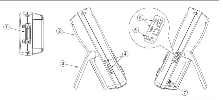
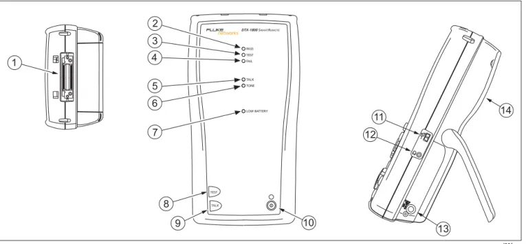
Physical Features
Figures 1-1 and 1-2 describe the tester’s features. Figure 1-3 describes the smart remote’s features.
TALK MONITOR ENTER TEST SAVE SPECIAL FUNCTIONS SETUP AUTO TEST SINGLE TEST EXIT F1 F2 F3 1 2 3 4 5 6 7 8 9 10 11 amd29f.eps
Getting Acquainted
Basic Features
1
1-9
A
LCD display with backlight and adjustablebrightness.
B
P
: Starts the currently selected test. Activates thetone generator for twisted pair cabling if no smart remote is detected. The test starts when both testers are connected.
C
N
: Saves Autotest results in memory.D
Rotary switch selects the tester’s modes.E
M
: On/off key.F
O
: Press to use the headset to talk to the person atthe other end of the link.
G
G
: Press to switch the backlight between brightand dim settings. Hold for 1 second to adjust the display contrast.
H
B C A D
: Arrow keys for navigating through screens and incrementing or decrementing alphanumeric values.I
H
: Enter key selects the highlighted item from amenu.
J
I
: Exits the current screen without saving changes.K
A
B
C
: The softkeys provide functionsrelated to the current screen. The functions are shown on the screen above the keys.
1-10
amd33f.eps
Getting Acquainted
Basic Features
1
1-11
A
Connector for twisted pair interface adapters.B
Cover for the module bay. Slide off the cover to installoptional modules, such as the fiber module.
C
Bail.D
DTX-1800 and DTX-1200: Slot and activity LED for theremovable memory card. To eject the card, push in then release the card.
E
USB ( ) and RS-232C ( : DTX-1800,DTX-1200) ports for uploading test reports to a PC and updating the tester’s software. The RS-232C port uses a custom DTX cable available from Fluke Networks. See Chapter 12 for more information.
F
Headset jack for talk mode.G
Connector for the ac adapter. The LED turns on whenthe tester is connected to ac power.
• Red: Battery is charging.
• Green: Battery is charged.
• Flashing red: Charge timeout. The battery failed
to reach full charge within 6 hours. See “If Something Seems Wrong” in Chapter 12.
1-12
amd30f.eps
Getting Acquainted
Basic Features
1
1-13
W
Caution
All the LEDs flash if the smart remote detects excessive voltage on the cable. Unplug the cable immediately if this occurs.
Note
The LEDs also act as a battery gauge. See Figure 1-5 on page 1-17.
A
Connector for twisted pair interface adapters.B
Pass LED lights when a test passes.C
Test LED lights during cable tests.D
Fail LED lights when a test fails.E
Talk LED lights when the smart remote is in talkmode. Press
O
to adjust the volume.F
Tone LED lights and the tone generator turns onwhen you press
P
, but the main tester is notconnected.
G
Low battery LED lights when the battery is low.H
P
: Starts the test currently selected on the mainunit. Activates the tone generator for twisted pair cabling if no main tester is detected. The test starts when both testers are connected.
I
O
: Press to use the headset to talk to the person atthe other end of the link. Press again to adjust the volume. Press and hold to exit talk mode.
J
M
: On/off key.K
USB port for updating the tester’s software with aPC.
L
Headset jack for talk mode.M
Connector for the ac adapter, as described in Figure1-2.
N
Cover for the module bay. Slide off the cover to installoptional modules, such as the fiber module.
1-14
Changing the Language
To change the tester’s language:
1 Turn the rotary switch to SETUP.
2 Use D to highlight Instrument Settings at the
bottom of the list; then press H.
3 Use
C
andD
to find and highlight Languageon tab 2 at the bottom of the list; then press
H
.4 Use D to highlight the desired language; then
press H.
5 Use the arrow keys and H to find and change
other local settings on tabs 2, 3, and 4 under
Instrument Settings.
Powering the Tester
*W
Warning
Read the safety information at the beginning of Chapter 2 before using the tester.
You can power the tester with the ac adapter included or with the removable lithium ion battery pack.
If the tester does not turn on, refer to “If Something Seems Wrong” in Chapter 12.
Charging the Battery
• To charge the battery, connect the ac adapter to the
battery pack, as shown in Figure 1-4.
• You may charge the battery when it is attached or
detached from the tester. Figure 1-4 shows how to remove the battery.
• The battery charges fully in about 4 hours with the
tester off. A fully-charged battery lasts for at least 12 hours of typical use.
Getting Acquainted
Basic Features
1
1-15
Note
The battery will not charge at temperatures outside of 0 °C to 45 °C (32 °F to 113 °F). The battery charges at a reduced rate between 40 °C and 45 °C (104 °F and 113 °F).
• If the battery does not reach full charge within 6
hours, the battery LED flashes red. Verify that the battery was within the temperature range given above during charging and that the correct ac adapter was used. Disconnect then reconnect ac power and try charging the battery again. If the battery does not charge the second time, retrain the battery gauge as described in Chapter 12.
• If the battery LED flashes red or the tester will not
turn on, see “If Something Seems Wrong” in Chapter 12.
Removing the battery Charging the battery
amd124f.eps
1-16
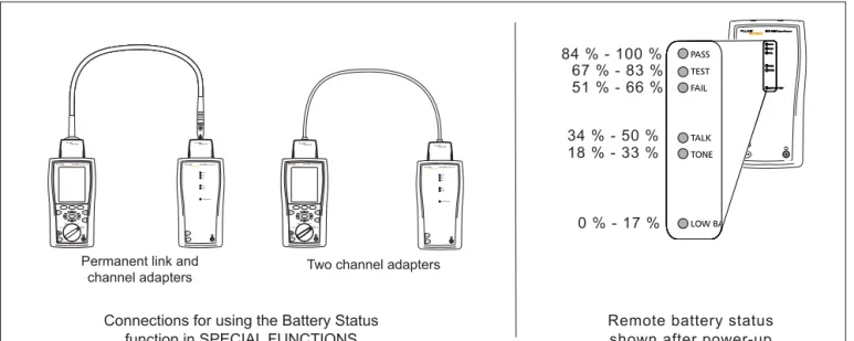
Checking the Battery Status
The battery status icon ( ) near the upper-right
corner of the tester’s main screens shows the battery’s charge level. The smart remote’s LEDs show the smart remote’s battery status at the end of the power-up cycle, as shown in Figure 1-5.
To see more information about battery status:
1 On the main Autotest screen, verify that the media
type is set to Twisted Pair. Press
J
Change Mediato change it if necessary.
2 Connect the tester and smart remote as shown in
Figure 1-5. You may also connect the testers through a link.
3 Turn the rotary switch to SPECIAL FUNCTIONS.
4 Use
D
to highlight Battery Status; then pressH
.The Time Remaining value tells you approximately
how long the main tester’s battery will last based on the last 3 minutes of use.
The accuracy of the battery gauge may drift over time. If the battery status information seems incorrect, retrain the battery gauge as described in Chapter 12.
Getting Acquainted Basic Features
1
1-17
TEST LOW BATTERY TONE TALK FAIL TEST PASS TALK LOW BA TONE TALK FAIL TEST PASSRemote battery status shown after power-up
PM06 TEST LOW BATTERY TONE TALK FAIL TEST PASS TALK TALK MONITOR ENTER TEST SAVE SPECIAL FUNCTIONS SETUP AUTO TEST SINGLE TEST EXIT F1 F2 F3 TEST LOW BATTERY TONE TALK FAIL TEST PASS TALK TALK MONITOR ENTER TEST SAVE SPECIAL FUNCTIONS SETUP AUTOTEST SINGLETEST EXIT F1 F2 F3
Connections for using the Battery Status function in SPECIAL FUNCTIONS
TEST LOW BATTERY TONE TALK FAIL TEST PASS TALK TEST LOW BATTERY TONE TALK FAIL TEST PASS TALK TEST LOW BATTERY TONE TALK FAIL TEST PASS TALK TEST LOW BATTERY TONE TALK FAIL TEST PASS TALK TEST LOW BATTERY TONE TALK FAIL TEST PASS TALK
Permanent link and
channel adapters Two channel adapters
0 % - 17 % 18 % - 33 % 34 % - 50 % 51 % - 66 % 67 % - 83 % 84 % - 100 % amd102f.eps
1-18
About Link Interface Adapters and Modules
Link interface adapters provide the correct jacks and interface circuitry for testing different types of twisted pair LAN cabling.
The channel and permanent link interface adapters provided are suitable for testing cabling up to Cat 6. Optional coaxial adapters let you test coaxial cabling. For information on other adapter types, contact Fluke Networks or visit the Fluke Networks website.
Figure 1-6 shows how to attach and remove adapters.
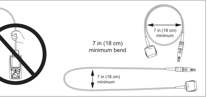
W
Caution
To avoid damaging the permanent link adapter and to ensure maximum accuracy of test results, never pinch, kink, or crush the adapter’s cable. Follow the handling guidelines given in Figure 1-7.
Modules provide optional testing capabilities. For example, the DTX-MFM2, DTX-GFM2, and DTX-SFM2 modules let you certify fiber optic cabling. The DTX-NSM module lets you verify network service. See Chapters 6 and 9 for details on these modules.
TALK MONITOR ENTER TEST SAVE SPECIAL FUNCTIONS SETUP AUTO TEST SINGLE TEST EXIT F1 F2 F3 TALK MONITOR ENTER TEST SAVE SPECIAL FUNCTIONS SETUP AUTO TEST SINGLE TEST EXIT F1 F2 F3 amd35f.eps
Getting Acquainted
Basic Features
1
1-19
amd36f.eps
1-20
The DTX-PLA001 universal permanent link adapter has a removable personality module. These may be changed to customize the adapter for different jack configurations. To change the personality module (refer to Figure 1-8):
1 Ground yourself by touching a grounded, conductive
surface.
2 Remove the link interface adapter from the tester.
3 Use your fingers to unscrew the screw on the
personality module.
4 Store the module in its original, static protection bag.
5 Put the new module in place and tighten the screw
with your fingers.
W
Caution
Tighten the screw snugly with your fingers only. Do not overtighten. Doing so can damage the module or the end of the cable.
Static sensitive device Personality module TALK MONITOR ENTER TEST SAVE SPECIAL FUNCTIONS SETUP AUTO TEST SINGLE TEST EXIT F1 F2 F3 amd74f.eps
Figure 1-8. Changing the Personality Module
The optional DSP-PLCAL automated calibration kit lets you calibrate your permanent link adapters to
compensate for physical changes that occur over time to the adapter’s cable and other components. Contact Fluke Networks for more information.
Getting Acquainted
Basic Features
1
1-21
Verifying Operation
The tester performs a basic self test when you turn it on. To run a more thorough self test for an acceptance test or as part of a routine equipment check:
1 Connect the main and remote testers as shown in
Figure 1-9.
2 Turn the rotary switch to SPECIAL FUNCTIONS.
3 Use
D
to highlight Self Test; then pressH
.4 If a fiber module is installed, select Mainframe.
5 Press
P
.If the tester reports an error, refer to “If Something Seems Wrong” in Chapter 12. PM 06 Permanent link adapter Channel adapter TEST LOW BATTERY TONE TALK FAIL TEST PASS TALK TALK MONITOR ENTER TEST SAVE SPECIAL FUNCTIONS SETUP AUTO TEST SINGLE TEST EXIT F1 F2 F3 amd41f.eps
1-22
Checking the Hardware and Software Versions
To see information about the tester’s hardware, software, and the test limits and cable types databases:
1 Connect the tester and smart remote through
adapters, as in Figure 1-9.
2 Turn the rotary switch to SPECIAL FUNCTIONS.
3 Use
D
to highlight Version Information; thenpress
H
.4 Use the softkeys to switch between the tester and
remote’s information, and between information for the mainframe and any modules or adapters attached.
To determine if your tester needs a software update, visit the Fluke Networks website to see if an update is available. See Chapter 12 for details on updating the tester's software.
The Main Autotest Screen
The Autotest automatically runs all the tests necessary to certify that cabling meets the requirements of the selected test limit. You will probably use the Autotest more than any other of the tester’s functions.
When you first turn the rotary switch to AUTOTEST, the
main Autotest screen shows settings you should check before you start testing. Figure 1-10 describes this screen.
You can change these settings in SETUP, as described in
Getting Acquainted Basic Features
1
1-23
1 6 7 8 9 11 2 3 4 10 5 amd05f.epsA
The media type selected for testing.B
Battery status icon.C
Test Limit: The tester compares test results tothe selected limit to determine the PASS/FAIL result.
D
Cable Type: The type of cable to be tested.E
Outlet Configuration: The wire mapping used for testingtwisted pair cabling.
F
PressL
to check the memory status.G
PressK
to view the results of the previous test.H
If a copper adapter and a fiber module are installed, pressJ
to change the type of media you will test.I
Store Plot DataNo: Plot data is not saved, which lets you save more results.
Saved results show worst margins and worst values for each pair.
Standard: The tester displays and saves plot data for
frequency-based tests such as NEXT, return loss, and attenuation. The tester saves data for the frequency range required by the selected test limit.
Extended: The tester saves data beyond the frequency range
required by the selected test limit.
J
Folder: The folder where results will be saved.K
Operator, Site: The person using the tester. Site: The job sitename. These are stored with saved results.
1-24
Setting User Preferences
The following sections describe how to change settings you may want to adjust when you first start using the tester.
Changing the Date, Time, and Date/Time Formats
1 Turn the rotary switch to SETUP, use
D
tohighlight Instrument Settings; then press
H
.2 Press
C
to go to the tab with the Date and Timeselections.
3 Use
D
to highlight the setting you want tochange; then press
H
.4 To change numbers in the date or time on the Date
or Time screen, use
B
C
to highlight the number;then use
A
D
to change the number.Press
N
when you are done.5 To change the date or time format, press
J
Change Format on the Date or Time screen. Use
D
to highlight the format you want; then pressH
.Changing the Length Units
1 Turn the rotary switch to SETUP, use
D
tohighlight Instrument Settings; then press
H
.2 Press
C
to go to the tab with the Length Unitsselection.
3 Use
D
to highlight Length Units; then pressH
.4 Use
D
to highlight the setting you want; thenpress
H
.Changing the Numeric Format
The tester can show decimal fractions with a decimal point (0.00) or a comma (0,00).
1 Turn the rotary switch to SETUP, use
D
tohighlight Instrument Settings; then press
H
.2 Press
C
to go to the tab with the Numeric Formatselection.
3 Use
D
to highlight Numeric Format; then pressH
.4 Use
D
to highlight the setting you want; thenGetting Acquainted
Setting User Preferences
1
1-25
Adjusting the Display Contrast
1 Press and hold
G
.2 Use
B
C
for coarse adjustments andK
FineL
Fine for fine adjustments.J
Default Setting sets the contrast to the defaultlevel.
3 Press
H
when you are done.The setting is retained when you turn the tester off. The contrast setting does not affect the battery life.
Setting the Power Down Timer
The power down timer turns off the tester after a selected period of inactivity. The timer starts when the backlight timer times out. If the backlight timer is disabled, the power down timer starts whenever the tester is not being used.
The smart remote turns off after 30 minutes of inactivity. This setting is not adjustable.
Note
The power down timer is inactive when the ac adapter is connected or when the USB or RS-232 serial port is active.
To set the power down timer:
1 Turn the rotary switch to SETUP, use
D
tohighlight Instrument Settings; then press
H
.2 Press
C
to go to the tab with the Power DownTime-Out setting; then press
H
.3 Use
D
to highlight the setting you want; thenpress
H
.Setting the Backlight Timer
The backlight timer turns off the backlight after a selected period of inactivity. Using the timer to turn off the backlight helps conserve battery power.
To set the backlight timer;
1 Turn the rotary switch to SETUP, use
D
tohighlight Instrument Settings; then press
H
.2 Press
C
to go to the tab with the Backlight Time-Outsetting. Use
D
to highlight Backlight Time-Out;then press
H
.3 Use
D
to highlight the setting you want; then1-26
Enabling or Disabling the Beeper
To enable or disable the tones for key presses and testing progress:
1 Turn the rotary switch to SETUP, use
D
tohighlight Instrument Settings; then press
H
.2 Press
C
to go to the tab with the Audible Tonesetting. Use
D
to highlight Audible Tone; thenpress
H
.3 Use
D
to highlight the setting you want; thenpress
H
.Overview of Memory Features
All DTX testers have internal memory that can store at least 250 Autotest results, including graphical data. The maximum capacity of internal memory depends on the space taken by the tester’s software.
The DTX-1800 and DTX-1200 testers can also store up to 500 Cat 6 Autotest results, including graphical data, on a 16 MB card. The testers can also use cards with higher capacity and secure digital (SD) memory cards.
Inserting and Removing the Memory Card
Insert the memory card into the slot on the side of the
tester. Figure 1-11 shows how to insert and remove the
card.
Formatting the Memory Card (DTX-1800 and
DTX-1200) or Internal Memory
Formatting erases all contents of the memory card or internal memory.
To format the memory card or internal memory:
1 Turn the rotary switch to SPECIAL FUNCTIONS, then
select Memory Status.
2 For a DTX-1800 or DTX-1200 with a memory card
installed, press
J
to select the memory card orinternal memory.
Getting Acquainted
Overview of Memory Features
1
1-27
Push card in until LED turns on Inserting the card
Removing the card Push card in to
release it
amd62f.eps
Figure 1-11. Inserting and Removing the Memory Card
Creating Folders
You can organize your test results by saving them in folders.
To create a folder:
1 DTX-1800, DTX-1200: Insert a memory card into the
tester.
2 Turn the rotary switch to SETUP.
3 Use
D
to highlight Instrument Settings; thenpress
H
.4 Press
D
to highlight Current Folder; then pressH
.5 DTX-1800, DTX-1200: Press
J
if necessary if youwant to create the folder on the memory card.
6 Press
L
Create Folder.7 Use
JKL
,BCAD
, andH
toenter a folder name. Press
N
when you are done.8 Use
AD
to highlight the new folder in the1-28
Setting the Storage Location (DTX-1800 and
DTX-1200)
To set the destination for saved results on a DTX-1800 or DTX-1200 tester:
1 Turn the rotary switch to SETUP, use
D
tohighlight Instrument Settings; then press
H
.2 Use
D
to highlight Result Storage Location;then press
H
.4 Use
D
to highlight Internal Memory or MemoryCard(if present); then press
H
.Note
If you change storage location, and the selected
Current Folder does not exist in the new
location, the tester creates a new folder with the current folder’s name in the new location.
See Chapter 12 for more information on memory features.
Options for Entering Cable IDs
When you save a test, you enter a name for the test. At a job site, you usually name each test with the identification code assigned to the link tested. You can enter this ID character by character, or by selecting the ID from a pre-generated list.
To select a method for entering cable IDs:
1 Turn the rotary switch to SETUP.
2 Use
D
to highlight Instrument Settings, thenpress
H
.3 Press
H
to select Cable ID Source.4 Use
D
to highlight an ID source, then pressGetting Acquainted
Overview of Memory Features
1
1-29
The tester offers the following methods for entering cable IDs:
• Auto Increment: You enter an ID for the first test you
save. After that, the tester increments the last
character of the ID each time you press
N
. SeeChapter 2 for details.
• List: Lets you select IDs from a list created with
LinkWare software and downloaded to the tester. See the LinkWare online help for details. The ID list can be sequential or random.
• Auto Sequence: Lets you select IDs from a list of
sequential IDs generated from a template in SETUP.
The horizontal, backbone, and campus templates follow the ID formats specified in the
ANSI/TIA/EIA-606-A standard. The Free Form template lets you
create your own pattern. See Chapter 2 for details.
• None: Lets you create an ID each time you press
N
.After you press
N
, you can also edit an existing ID beforeusing it for saving results.
To create a list of sequential IDs:
1 On the Auto Sequence screen, select a template.
2 On the Auto Sequence screen, select Start ID. Use the
softkeys,
BC A D
, andH
to enter thefirst ID in the sequential list. Press
N
when you are finished.3 Select Stop ID. Use the softkeys,
BC A D
,and
H
to enter the last ID in the sequential list.Press
N
when you are finished4 Press
L
Sample Listto see what the list will looklike.
When you use an ID from a list, the ID is marked with a “$”.
See Chapter 2 for more information on the Auto
1-30
Using the Talk Mode
The talk mode lets you talk to the person at the other end of a twisted pair or fiber link. Two-way communication over twisted pair requires one good wire pair. Two-way communication over fiber requires fiber modules and two fibers.
Note
The talk mode is disabled during cable tests.
1 Connect the tester and smart remote to the cabling.
2 Plug headsets into the headset jacks on the testers.
3 Press
O
on either the tester or smart remote, thenspeak into the headset’s microphone. To adjust the volume at the main unit use
AD
.At the smart remote, use
O
to cycle through thevolume settings.
4 To exit the talk mode at the main tester, press
I
,turn the rotary switch to a new position, or start a
test. At the smart remote, hold down
O
for twoseconds.
About LinkWare and LinkWare Stats
Software
The LinkWare Cable Test Management software
included with your tester lets you do the following:
• Upload DTX test results to PC. See Chapter 12.
• View test results.
• Add ANSI/TIA/EIA-606-A administration information
to records.
• Organize, customize, and print professional-quality
test reports.
• Update the tester’s software.
• Create and download data to the DTX, such as Setup
data and cable ID lists.
• Calibrate the permanent link adapters (DSP-PLCAL kit
required)
Getting Acquainted
About LinkWare and LinkWare Stats Software
1
1-31
Details about using LinkWare software are provided in the LinkWare Getting Started Guide and the online help available under Help on the LinkWare menu.
Updates to LinkWare software are available on the Fluke Networks website.
The LinkWare Stats Statistical Report option for LinkWare software provides statistical analysis of cable test reports and generates browsable, graphical reports.
LinkWare software includes a demo version of LinkWare Stats. Contact Fluke Networks or visit the Fluke Networks website for more information on LinkWare Stats.
2
-
1
Chapter 2
Tutorials on Setup and Test Procedures
The tutorials in this chapter guide you through setting up the tester, checking the tester’s status, testing twisted pair and fiber cabling, and setting up cable ID lists.
Preparing to Save Tests
Step 1: Checking the Memory Space Available
1-1 DTX-1800, DTX-1200: Insert a memory card into the
tester.
1-2 Turn the rotary switch to SPECIAL FUNCTIONS.
1-3 Use
D
to highlight Memory Status; then pressH
.1-4 DTX-1800, DTX-1200: Press
J
Int. Memory toswitch between memory card and internal memory status.
2
-
2
Step 2: Entering Job Information
Job information includes the operator name, name of the job site, and the customer’s company name. These settings are stored with results you save.
To enter job information:
2-1 Turn the rotary switch to SETUP.
2-2 Use
D
to highlight Instrument Settings; thenpress
H
.2-3 Press
C
to go to the tab with the Operator Namesetting. Press
H
to select Operator Name.2-4 Press
J
Create; then useJKL
,BCAD
, andH
to enter your name inthe box. Press
N
when you are done.2-5 Figure 2-1 describes the text editing screen.
2-6 Use
D
to highlight Site; then pressH
.2-7 Press
J
Create; then useJKL
,BCAD
, andH
to enter the job sitename in the box. Press
N
when you are done.2-8 Repeat steps 2-6 and 2-7 to enter the customer’s
Tutorials on Setup and Test Procedures
Preparing to Save Tests
2
2
-
3
1 2 3 4 5 amd120f.epsA
The characters available for use.To select a character to enter in the text box, use
ADBC
to highlight the character; then pressH
.The character is entered to the left of the cursor.
B
The text you are entering.C
The cursor. UseJ
andK
to move the cursor.D
The item you are editing.E
UseJKL
to move the cursor and delete characters.2
-
4
Step 3: Setting the Storage Location (DTX-1800
and DTX-1200)
To set the destination for saved results on a DTX-1800 or DTX-1200 tester:
3-1 Turn the rotary switch to SETUP, use
D
tohighlight Instrument Settings; then press
H
.3-2 Use
D
to highlight Result Storage Location;then press
H
.3-3 Use
D
to highlight Internal Memory orMemory Card(if present); then press
H
.Note
If you change storage location, and the selected
Current Folder does not exist in the new
location, the tester creates a new folder with the current folder’s name in the new location.
Step 4: Setting Up a Job Folder
You can organize test results by saving them in a folder named for the job.
To set up a job folder:
4-1 DTX-1800, DTX-1200: Insert a memory card into the
tester, if that is where you wan to create a folder.
4-2 Turn the rotary switch to SETUP.
4-3 Use
D
to highlight Instrument Settings; thenpress
H
.4-4 Press
D
to highlight Current Folder; then pressH
.4-5 Press
J
Create Folder.4-6 Use
JKL
,BCAD
, andH
toenter a folder name. Press
N
when you are done.4-7 Use
AD
to highlight the new folder in theTutorials on Setup and Test Procedures
Certifying Twisted Pair Cabling
2
2
-
5
Step 5: Selecting a Cable ID Source
Cable IDs are names you enter for tests you save. You can select IDs from a pre-generated list, or enter them manually after each test. For this tutorial, you will enter IDs manually.
To select a cable ID source:
5-1 Turn the rotary switch to SETUP.
5-2 Use
D
to highlight Instrument Settings; thenpress
H
.5-3 Press
H
to select Cable ID Source.5-4 Use
D
to highlight None; then pressH
.Certifying Twisted Pair Cabling
This tutorial familiarizes you with testing twisted pair cabling by guiding you through the following tasks:
• Attaching twisted pair adapters
• Checking the battery status and verifying operation
with twisted pair adapters
• Running an Autotest
• Viewing the Autotest results
2
-
6
Required Equipment
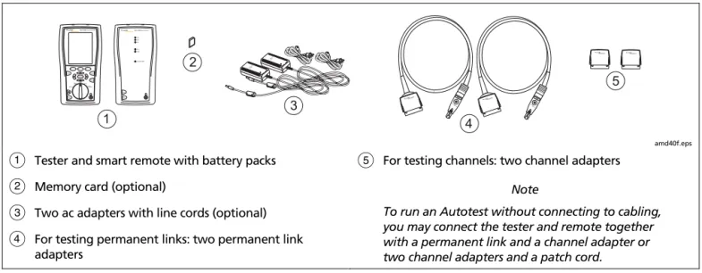
Figure 2-2 shows the equipment for testing twisted pair cabling. PM06 PM06 1 2 3 4 5 TEST LOW BATTERY TONE TALK FAIL TEST PASS TALK TALK MONITOR ENTER TEST SAVE SPECIAL FUNCTIONS SETUP AUTO TEST SINGLE TEST EXIT F1 F2 F3 amd40f.eps
A
Tester and smart remote with battery packsB
Memory card (optional)C
Two ac adapters with line cords (optional)D
For testing permanent links: two permanent linkadapters
E
For testing channels: two channel adaptersNote
To run an Autotest without connecting to cabling, you may connect the tester and remote together with a permanent link and a channel adapter or two channel adapters and a patch cord.
Tutorials on Setup and Test Procedures
Certifying Twisted Pair Cabling
2
2
-
7
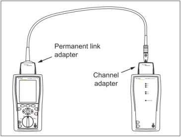
Step 1: Checking the Battery Status and Verifying
Operation with Twisted Pair Adapters
You should check the tester and smart remote’s battery status and verify all equipment is in good working order before going to the job site.
1-1 Connect the tester and smart remote together as
shown in Figure 2-3.
1-2 Turn the rotary switch to SPECIAL FUNCTIONS.
1-3 Use
D
to highlight Battery Status; then pressH
. PressI
when you are done.1-4 Use
D
to highlight Self Test; then pressH
.1-5 Press
P
to start the self test.Note
You can also check the battery status by connecting channel adapters with a patch cord, or by connecting the tester and smart remote through a link. PM 06 Permanent link adapter Channel adapter TEST LOW BATTERY TONE TALK FAIL TEST PASS TALK TALK MONITOR ENTER TEST SAVE SPECIAL FUNCTIONS SETUP AUTO TEST SINGLE TEST EXIT F1 F2 F3 amd117f.eps
Figure 2-3. Battery Status and Self Test Connections for Twisted Pair Adapters
2
-
8
Step 2: Selecting a Test Limit, Cable Type, and
Outlet Configuration
Select the test limit, cable type, and outlet configuration specified for the job. The outlet configuration determines which cable pairs are tested and which pair numbers are assigned to the pairs.
2-1 Turn the rotary switch to SETUP; then press
H
toselect Twisted Pair.
2-2 On the Twisted Pair menu use
D
andH
toselect Cable Type. Cables are organized in groups:
UTP: Unshielded twisted pair cable
FTP: Foil screened twisted pair cable
SSTP: Screened/shielded twisted pair cable
Custom: Cable types entered by a DTX user.
Manufacturer: Specific brands of twisted pair cable
2-3 Use
D
to highlight the group for the cable typeyou will test; then press
H
.2-4 Use
D
to highlight the cable type you will test;then press
H
.2-5 On the Twisted Pair menu, press
H
to select TestLimit.
2-6 The first Test Limit screen shows the most recently-used limits. To see the list of test limit groups, press
J
More.2-7 Use
D
andH
to select a different limitgroup, if necessary, and to select the test limit required for the job.
If you are connecting the permanent link and channel adapters together just to try an Autotest, select a Cat 6 Channel or equivalent limit.
2-8 If the currently-selected Outlet Configuration is not compatible with the selected Test Limit, the Outlet
Configuration screen appears. Use
AD
tohighlight an appropriate configuration; then press
H
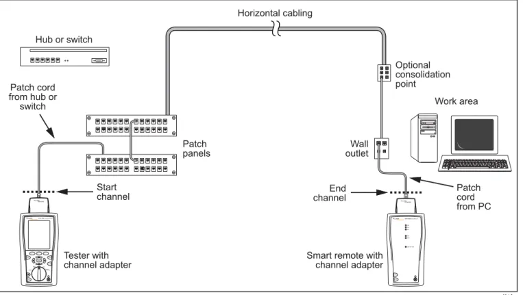
.Step 3: Running the Autotest
3-1 Attach the correct adapters to the tester and smart
remote.
3-2 Turn on the tester and smart remote; then connect
them to the cabling. Figures 2-4 and 2-5 show connections for permanent link and channel installations.