Swedish University of Agricultural Sciences
Faculty of Veterinary Medicine and Animal Science
Degree project / Swedish University of Agricultural Sciences,
Department of Animal Nutrition and Management, 585 Uppsala 2016
Degree project, 30hp Master Thesis Animal Science
Milking-time Test – Methodology
and Assessment of Vacuum
Recordings during Machine
Milking of Dairy Cows
Swedish University of Agricultural Sciences
Faculty of Veterinary Medicine and Animal Science Department of Animal Nutrition and Management
Milking-time Test – Methodology and
Assessment of Vacuum Recordings during
Machine Milking of Dairy Cows
Dragana Lazović
Supervisor: Sigrid Agenäs, SLU, Department of Animal Nutrition and Management
Jörgen Enickl, DeLaval AB, Tumba, Sweden
Ass. Supervisor: Majbritt Felleki, SLU, Department of Animal Nutrition and Management
Examiner: Kerstin Svennersten-Sjaunja, SLU, Department of Animal Nutrition and Management
Extent: 30 hp
Course title: Degree project in Animal Science
Course code: EX0551
Programme: Erasmus Mundus Food of Life (EMFOL)
Level: Avancerad A2E
Place of publication: Uppsala
Year of publication: 2016
Series name, part no: Degree project / Swedish University of Agricultural Sciences, Department of Animal Nutrition and Management, 585
On-line published: http://stud.epsilon.slu.se
Keywords: milking machines, milking-time tests, milking vacuum, sampling frequency, dynamic testing, dairy cow
Milking-time Test - Methodology and Assessment of Vacuum
Recordings during Machine Milking of Dairy Cows
Abstract
The aim of the study was to improve the basic understanding and the methodology of routine milking-time testing by determining the required sampling frequency and number of cows and milkings needed to be measured in order to yield representative results. Milking-time tests represent the most direct method to validate the system vacuum of a milking machine, both the aptitude of vacuum production and the vacuum regulation throughout the system. The vacuum was measured at five points along the milking machine in a milking parlour for six consecutive days, both during morning and evening milking. Three points were measured continuously during the whole milking session, the receiver and two points on the milkline, while the claw and the mouthpiece chamber vacuum (MPCV) was measured during the milking of six cows on each milking occasion. Data was collected at a frequency of 100 Hz and the possibility of obtaining equally reliable results of the milking-time tests with a lower sampling frequency of 10 Hz and 1 Hz was tested in the data analysis by using subsamples of the complete dataset. The sampling frequency of 10 Hz compared to the 100 Hz frequency gave reliable results for means of the claw vacuum and MPCV while the frequency of 1 Hz did not. The number of cows and milkings needed to be measured in order to yield representative results could not be determined without further data analysis.
Keywords: milking machines, milking-time tests, milking vacuum, sampling frequency, dynamic testing, dairy cow
Contents
Abstract 4 Abbreviations 7 1 Introduction 8 2 Literature review 9 2.1 Machine milking 9 2.1.1 Udder anatomy 9 2.1.2 Milk production 12 2.1.3 Milking machine 13 2.1.4 Milking routines 172.2 Interaction between the milking machine and the teat 19
2.2.1 Forces acting on the teat 19
2.2.2 Mechanism of machine milking 20
2.2.3 Liner compression of the teat 22
2.3 Milk-flow 23
2.3.1 Milk-flow of a single milking 23
2.3.2 Milk-flow of a single pulsation cycle 24
2.3.3 Milking time duration 24
2.3.4 Average milk-flow rate 25
2.4 Vacuum 26 2.4.1 System vacuum 26 2.4.2 Receiver vacuum 27 2.4.3 Milkline vacuum 27 2.4.4 Cluster vacuum 28 2.4.5 Vacuum fluctuations 30
2.4.6 Vacuum and udder health 32
2.5 Measuring vacuum 33
2.5.1 Vacuum measuring equipment 34
3 Aims 36
4 Materials and Methods 37
4.1 Experimental animals 37
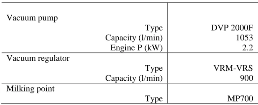
4.2 Milking system parameters 38
4.4 Teat measurements and teat scoring 40
4.5 Vacuum recordings 41
4.6 Mathematical calculations 45
4.7 Data handling and statistical analysis 46
5 Results and Discussion 47
5.1 Teat measurement and teat scoring 47
5.2 Vacuum measurements 48
5.2.1 Vacuum in the receiver and the milkline 48
5.2.2 Claw chamber vacuum and MPCV 50
5.2.3 Claw chamber vacuum and MPCV means as functions of Hz 54
5.3 Mathematical calculations 56
6 Conclusion 58
References: 59
Abbreviations
ACR – Automatic Cluster Removal AMS – Automatic Milking System
ASAE - The American Society of Agricultural Engineers
CEMA - Associations of Manufacturers of Agricultural Machinery CMT – California Mastitis Test
FIL – Feed-back Inhibitor of Lactation
ICRPMA - The International Committee on Recording the Productivity of Milk Animals
IDF – International Dairy Federation
ISO – International Organization for Standardization kPa - Kilopascal
MPCV – Mouthpiece Chamber Vacuum NMC – National Mastitis Council VMS – Voluntary Milking System
1 Introduction
In order to achieve optimal milking efficiency of a dairy operation the cows need to be milked as completely, gently and quickly as possible to ensure sufficient milk removal and avoid adverse effects on the udder health or the quality of the product (Bruckmaier, 2001). The milking machine is a major investment of the dairy operation and has to be adequately designed, properly cleaned and maintained and used according to the manufacturer’s instructions (Akam et al., 1989). According to the International Organization for Standardization (ISO) 3918:2007 standard milking machine tests can be carried out as dry tests, wet tests, milking-time tests or cleaning-time tests (ISO, 2007a). ISO 6690:2007 standard does not require milking-time tests for milking machine validation (ISO, 2007c) while the National Mastitis Council (NMC, 2014) proposes milking-time tests as means of evaluating the vacuum and the NMC provides guidelines and testing methods. The milking-time tests measure vacuum under normal conditions in the milking parlour during milking of live animals and allow for the interaction of milker, cow and machine to be assessed. They represent the most direct method to validate the vacuum system of the milking machine, both the aptitude of vacuum production and vacuum regulation throughout the system (Reinemann et al., 2007).
Since milking is time consuming and labour intensive and the average herd sizes are increasing in many parts of the world the importance of efficient milking with higher parlour throughput is increasing (Edwards et al., 2014). Vacuum magnitude, together with pulsation settings and liner compression, are some of the major factors affecting the milk-flow rate and milking speed (Mein et al., 2013). Furthermore, it has been demonstrated that vacuum magnitude as well as the pattern of the milk-flow and vacuum during milking in form of vacuum fluctuations, bimodality and overmilking, can affect udder health (Thompson et al., 1978; Thiel et al., 1973; O’Callaghan et al., 1976; Langlois et al., 1981; Natzke & Bray, 1985; Tamburini et al., 2010).
The aim of the study was to improve the basic understanding and the methodology of routine milking-time testing by determining the required sampling frequency and number of cows and milkings needed to be measured in order to yield representative results.
2 Literature review
2.1 Machine milking
The main function of machine milking is to milk dairy animals completely, gently and quickly with no adverse effects on udder health or the raw milk quality (Bruckmaier, 2001). The interaction between the cow and the machine will influence the efficiency of the process. The milking operator is equally important for successful milking as he/she acts as the mediator between the two through proper equipment handling and milking routines (Hamann, 1995). Evaluations of milking management need to include aspects of both the milking machine and how the machine is handled.
2.1.1 Udder anatomy
In order to explain the mechanism and requirements of machine milking basic understanding of udder anatomy and physiology is needed. The cow udder consists of four mammary glands with separate glandular tissue, milk collection and duct system ending with a teat. The basic functional unit of the mammary gland is an alveolus. Alveoli are formed by a single layer of cylindrically arranged secretory epithelial cells which are connected with tight junctions. Myoepithelial cells surround alveoli and milk ducts. In response to oxytocin, myopethelial cells contract and cause milk to move down the ducts (Reece et al., 2015). A schematic representation of the alveolus with its major parts outlined is shown in Figure 1.
Figure 1. Schematic representation of the alveolus. Reprinted from Dukes 'Physiology of Domestic Animals, Twelfth Edition, edited by Melvin J. Swenson and William O. Reece. Copyright © 2004 by Cornell University. Used by permission of the publisher, Cornell University Press.
Alveoli are organized into lobules which are further grouped into lobes. Milk ducts terminate in the gland cistern which continues into the teat cistern and teat canal (ductus papillares) ending with a single opening at the teat tip. Fürstenberg’s rosette, a folded double layer of columnar epithelium, separates teat cistern and teat canal. The teat canal epithelium produces keratin which prevents bacterial colonization due to its antibacterial nature. In addition bacteria bound to the keratin are expelled together with the milk during each milking. Teat sphincter muscle closes the teat and withholds milk in the teat (Reece et al., 2015). A schematic representation of the lobuloalveolar and ductal system of the bovine udder is presented in Figure 2. Rear quarters yield significantly more milk than the front ones (Tančin et al., 2006). The difference in yield reported
in the literature ranges between 6.2% in favour of rear quarters reported by Tančin et al. (2006) and 20 % found by Berglund et al. (2007).
Figure 2. Schematic representation of the lobuloalveolar and ductal system of bovine udder. Reprinted from Dukes 'Physiology of Domestic Animals, Twelfth Edition, edited by Melvin J. Swenson and William O. Reece. Copyright © 2004 by Cornell University. Used by permission of the publisher, Cornell University Press.
Anatomical traits of the teat that affect milk-flow rate include diameter of the teat canal, its length and the tonus of the teat sphincter (Macuhova & Bruckmaier, 2005). In a study performed by Baxter et al. (1950) by using a teat cannula with a constant bore it was shown that the size of the teat orifice controls the flow rate. Grindal et al. (1991a) found that the length of the canal is inversely correlated to the risk of new intermammary infection while the udder quarters with a higher flow rate were also at a higher risk. Since the flow rates have increased greatly through breeding and selection more attention needs to be directed toward hygiene and disease prevention (Grindal & Hillerton, 1991b). Breeding and selection also resulted in shorter and thinner teats in modern dairy cows. The teat canal length is negatively correlated to peak and average flow rate while the external teat measurements of length and diameter are not correlated to milking traits (Weiss et al., 2004). Even though the tonus of smooth
muscles can hinder peak-flow its effect is not important when using conventional liners (Mein & Reinemann, 2014).
2.1.2 Milk production
Lactation is a combination of two processes, milk secretion and milk removal, resulting in a unique product that is the perfectly balanced food source for the new-born. Milk secretion is a continuous process, but regular milk removal is a pre-requisite to maintain milk production. Storage capacity within the gland will determine the rate of milk production. Build-up of pressure in the alveoli impairs blood flow leading to reduced milk secretion rate. Autocrine factors, secreted locally by the mammary gland epithelium, suppress enzymes needed for synthesis of milk components thus decreasing the rate of milk production (Reece et al., 2015). Wilde et al. (1995) claimed they isolated a protein of relative molecular mass of 7600 they named feed-back inhibitor of lactation (FIL). FIL was separated by anion-exchange chromatography from goat’s milk. Authors reported that, after intramammary injections of the protein, FIL inhibited synthesis of milk components thus decreasing the rate of milk production as well. Even though the N-terminal amino acid sequence reported by the authors could not be related to any other milk protein, until today no protein related to the molecular mass associated with FIL has been identified nor was the full amino acid sequence published (Collier et al., 2012). Matsuda et al. (2004) found that the neuropeptide serotonin, mediated by prolactin which stimulated expression of genes necessary for serotonin synthesis in the mammary gland, induced involution of mammary tissue of mice. Hernandez et al. (2008) confirmed the presence of a gene, up-regulated by prolactin, that mediated serotonin synthesis in an in-vitro study on bovine mammary tissue. Furthermore, the authors demonstrated that serotonin, both in-vitro and in-vivo, suppressed the milk yield. Since milk production is stimulated by prolactin (Svennersten-Sjaunja & Olsson, 2005) and inhibited by serotonin the whole process is controlled by a negative feedback mechanism in which prolactin both stimulates the milk production and the negative feedback mechanism by up-regulating genes necessary for serotonin synthesis (Collier et al., 2012).
In a full dairy cow udder approximately 80% of milk is stored in the alveolar compartment (Reece et al., 2015). This means that only 20% of milk can be extracted without the activation of the milk ejection reflex. Milk ejection is a neuro-endocrine reflex that is mediated by the neuropeptide oxytocin. It is released from the pituitary gland as a response to the activation of touch-sensitive receptors in the teats. The receptors can be stimulated by a calf during
suckling or by manual handling or preparation before hand or machine milking. The milking machine can also provide stimulation for activation of the milk let-down reflex (Svennersten-Sjaunja et al., 2004). After oxytocin is released into the blood it interacts with the receptors on the myoepithelial cells causing their contraction. Contraction of cells on the alveoli increases intraalveolar pressure forcing the milk into the ducts, while the contraction of the cells around the ducts induces shortening and widening of the ducts reducing the resistance to the milk flow through the duct system (Crowley & Armstrong, 1992).
2.1.3 Milking machine
In order to achieve optimal milking efficiency the milking machine has to be adequately designed, properly cleaned and maintained and used according to the manufacturer’s instructions (Akam et al., 1989).
Development of milking machines is an old concept dating to early 1700s when it was attempted to milk cows by inserting a straw in the teat canal. The first operational vacuum milking machine was developed in 1860 in Scotland (Wilson, 1958). The first machine that accomplished commercial success was the Murchland machine, developed by a plumber in England in 1889. This machine had a manually operated vacuum pump that maintained a working vacuum of 37 kPa. A milking machine developed by Nicholson and Grey in 1891 operated under 45 kPa vacuum level which is in the range of recommended vacuum level in use today (Reinemann, 2005).
Regardless of the design of milking installations all milking machines work on the same principle. The installation is, essentially, an enclosed pipeline system that connects various vessels and components providing flow paths for air and milk. The system is kept under constant vacuum which enables movement in both air and milklines with atmospheric pressure forcing air flow and intra-mammary pressure forcing the milk into the system. Flow is a result of the combination of these two forces and since it needs to be continuous both air and milk have to be evacuated from the system at the appropriate rate. Milk is sucked from the udder by application of vacuum at the teat end and transported through a pipeline system into a collection tank (Akam et al., 1989). Basic components of every milking installation include: a vacuum system, pulsators, milking units or clusters and a milk removal system (Ohnstad, 2011).
The vacuum system consists of a vacuum pump with a reserve tank, vacuum regulator, pipelines and long pulse tubes which form an enclosed space
(Ohnstad, 2011). Vacuum is defined as any pressure that is below the atmospheric. It is created by the vacuum pump which evacuates air from the system. Asides from milking the cows, the created vacuum is used to transport milk to the receiver and collection tanks and during washing (Wattiaux, 1995). An interceptor, mounted on the main vacuum line, prevents dust and liquids from entering the vacuum pump. Vacuum level of an installation is the difference between the atmospheric pressure and pressure in the system. Kilopascal (kPa) is the official, international unit of vacuum with 100 kPa representing the pressure difference between atmospheric pressure and absolute vacuum. Besides kPa the unit mm of Hg is commonly used. For this reason it is useful to mention their conversion rate; 1 mm Hg equals 0.1333 kPa (Akam et al., 1989). The vacuum regulator controls the level of vacuum by the amount of air it admits into the system. A vacuum gauge is used for detection of abnormal levels and fluctuations of vacuum (Ohnstad, 2011).
The pulsator enables the action of the teatcup. It is a simple valve that admits vacuum and atmospheric air intermittently to the pulsation chamber causing the liner to open and close during milking. Collapse of the liner is achieved by admission of air into the pulsation chamber, while the opening is facilitated by the evacuation of the air from the pulsation chamber (Ohnstad, 2011). Pulsators operate under frequencies of 45 to 65 cycles per minute commonly called pulsation rate. Simultaneous pulsators admit vacuum or air to all four teatcups at the same time while alternate pulsators admit air or vacuum to two chambers at a time (Wattiaux, 1995).
The milking cluster consists of four teatcups, a claw, a long milk tube and a long pulsation tube. Each teatcup has an outer shell, a rubber liner, a short milk tube and a short pulsation tube (Ohnstad, 2011). Shields can be fitted in the mouthpiece chamber as means of mastitis reduction to prevent milk droplets from impacting teat ends during vacuum fluctuations (Akam et al., 1989). Materials used for shell production can be stainless steel or plastic or a combination of both. The liner, which is essentially a rubber sleeve with a mouthpiece, forms a pulsation chamber between the shell and the liner. The pulsation chamber is connected to the claw with a short pulsation tube and the mouthpiece chamber is connected to it with a short milk tube. Milking and pulsation vacuum is delivered to the claw through long milk and long pulsation tubes (ISO, 2007a). An air admission hole in the claw stabilizes the vacuum and the milk flow during milking. Air helps milk evacuation and prevents development of slugs and extensive vacuum fluctuations (Ohnstad, 2011). One-way valves can be mounted in the claw, the short milk tube or the liner to prevent
reverse flow of milk which could cause teat canal contamination and lead to mastitis. Claw is usually made from a combination of steel and plastics and it weighs about 2.5 kg. (Akam et al., 1989). Good visibility of the milk flow aids the milker in assessment of machine and operations adjustment, especially in the beginning and the end of a milking session (Wattiaux, 1995). A too light cluster has a negative impact on the completeness of milking resulting in high levels of strippings or residual milk in the udder while a too heavy cluster results in clusters falling off during milking. In order to allow adequate milk flow claw bowl capacity should be at least 80 ml, while short milk tubes, short pulsation tubes and long milk tubes should have a bore of at least 8 mm, 5 mm and 12.5 mm respectively (Akam et al., 1989). From the claw milk is transferred through long milk tubes and milklines into a receiver (ISO, 2007a).
Milklines have a dual function, to evacuate milk and air from the claw and to provide milking vacuum. Depending on the position of the milk inlet valve to the milkline or the calibrated recorder jar milking systems can be high-level milking systems with the milk inlet more than 1.25m above the animal standing level; mid-level milking system with the milk inlet between 0m and 1.25m and low-line milking systems with milk inlet below the animal standing level (ISO, 2007a). Internal diameter and slope of the milklines has to be designed in a way that the vacuum between the receiver and any point in the milkline does not drop more than 2 kPa under standard operating conditions (ISO, 2007b). Air and milk are separated in the receiver. Milk is extracted with a centrifugal milk pump, mechanical valve releasers or with a direct connection to a refrigerated bulk tank operating under vacuum. A glass vessel called sanitary trap, which prevents liquids from entering the air pipeline, is fitted in the vacuum line next to the receiver. The presence of milk in the sanitary trap is an indicator of a machine flaw (Akam et al., 1989).
A calibrated recorder jar measures the milk quantity from an individual animal during milkings (ISO, 2007a). Milk is collected into a calibrated recorder jar and it passes through a meter that measures the yield in batches. The calibrated recorder jar can also perform representative sampling for milk quality analysis. In systems without calibrated recorder jars milk yield can be measured by portable milk meters (Akam et al., 1989). Devices called milk flow indicators can be added to detect milk flow visually (ISO, 2007a). Modern machines’ milk flow detectors monitor and electronically record flow rate and activate automatic cluster removal (ACR) when the flow falls to a predetermined value. Two main advantages of ACR are prevention of overmilking and decreased workload (Akam et al., 1989).
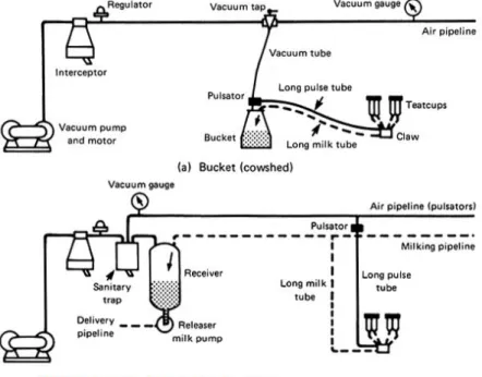
Three basic layouts of milking machines include: 1) bucket milking which collects milk into a bucket placed next to the cow in the shed; 2) pipeline system with cows milked in the shed and milk transported with a pipeline system to a central collection tank and 3) parlour system with centralized equipment where cows come to the parlour in order to be milked (Akam et al., 1989, Wattiaux, 1995). Figure 3. shows the basic layouts of milking machine installations.
Figure 3. Principal layouts of milking machine installations: (a) Bucket (cowshed) milker with milk collected into a bucket placed next to the cow in the shed; (b)
Milking pipeline (cowshed and parlour) with cows milked in the shed and milk transported with a pipeline system to a central collection tank and parlour system with centralized equipment where cows come to the parlour in order to be milked (c) Recorder (parlour) installation with a calibrated recorder jar that collects milk and as it passes through a meter measures the yield in batches. Dashed line represents the milk-flow path and black line the air-flow path (adapted from Akam et al., 1989).
Development of automatic milking systems (AMS) or milking robots reduced the work load allowing for milking without the human presence. Cows are milked individually and if a voluntary milking systems (VMS) is installed cows are given a chance to access the robot willingly during the whole day (Kovac et al., 2001). One single-stall milking robot unit can milk approximately 60 cows depending on milk yield, milk-flow rate, milking efficiency and cow traffic. AMS and VMS systems automatically collect data regarding the health status of the animal, milk quality and milk yield (De Koning & Rodenburg, 2004).
The ISO in collaboration with the International Dairy Federation (IDF), European Committee of Associations of Manufacturers of Agricultural Machinery (CEMA) and the International Committee on Recording the Productivity of Milk Animals (ICRPMA) prepared international standards for milking machine installations (Milking machine installations – Vocabulary ISO 3918:2007; Milking machine installations - Construction and performance ISO 5707:2007) which propose minimum performance requirements and define dimensional requirements for proper milking machine function. ISO standard 6690:2007 on mechanical tests of milking machines describes test procedures that can verify the compliance of the machine and its settings to requirements proposed by the organization.
2.1.4 Milking routines
Even though modern dairy cows are exceedingly adapted to machine milking through selection and breeding programmes the physiological regulation of milk ejection and milk removal prevails. For this reason milking equipment and milking routines have to be optimized to meet physiological requirements of the animal ensuring a successful lactation, optimal animal health and quality of the final product (Bruckmaier, 2001).
The suckling bouts of the calf include three actions by the young, pre-stimulation, milk intake and post-stimulation (Lidfors et al., 1994). Oxytocin secretion is affected by the type of the tactile stimuli. Akers & Lefcourt (1982)
found that calf’s suckling induced a significantly higher oxytocin release compared to machine milking. It should be noted that the cows were housed with calves. On the other hand, cows that were not housed with calves, compared to the ones that were, had a higher oxytocin release during machine milking. Even though this result was not significant it implies that the calf’s presence might have modified the response and different results might be obtained if the animals were managed differently. On the contrary, a study by Lupoli et al. (2001) found that a greater oxytocin release is seen in cows that were suckled than in cows that were machine milked. The authors propose that the discrepancy in their results and the ones from Akers & Lefcourt (1982) could be explained by the suckling frequency. While the study by Lupoli et al. (2001) restricted suckling to two times a day by covering the udders with protective nets, calves were allowed to suckle freely in the study by Akers & Lefcourt (1982). Furthermore, Lupoli et al. (2001) examined oxytocin release in cows that were housed with their calves but not allowed to suckle. Oxytocin level was significantly lower during machine milking of these cows when compared to cows that were suckled. Gorewit et al. (1992) found that hand milking provided a greater and more rapid oxytocin response than machine milking. Other stimuli, like the stimulation of the vaginocervical area can induce oxytocin release and this response can be greater than mammary stimulation (Schams et al., 1982). Since oxytocin is released during feeding as well, the practice of feeding during milking has been employed (Bruckmaier & Blum, 1998; Svennersten-Sjaunja & Olsson, 2005).
Pre-stimulation prior to milking machine attachment is important in order to ensure activation of the milk ejection reflex which will facilitate milk flow to the gland cistern. Proper pre-stimulation will influence milk flow and milking duration and prevent milking on empty teats (Svennersten-Sjaunja et al., 2004). Time interval between the start of pre-stimulation and milk ejection commencement or lag time of modern dairy cows ranges between 1 and 2 minutes and varies with the udder fill (Bruckmaier & Hilger, 2001). As the lactation progresses, after its peak, milk production gradually decreases. With a lower milk production more time is necessary to fill the udder completely and this can lead to lower udder fill at milking time, especially if the milking interval is shorter (Bruckmaier, 2001). Prolonged milk ejection at lower udder fill is not caused by differences in oxytocin release (Mayer et al., 1991) but rather by slower response at the udder level with higher concentration of oxytocin needed to empty the partially filled alveoli. Since the degree of udder fill is influenced by milking intervals and stage of lactation these factors have to be considered when milking routines are adopted (Bruckmaier, 2001).
All milk stored in the alveoli cannot be ejected at once and continuous milk evacuation from the cisternal compartment has to be provided in order to enable milk let down. This means that milk ejection is a continuous process and stimulation to the teats is needed during the whole milking session (Bruckmaier et al., 1994). While the pre-stimulation prior to milking machine attachment is manual, the continuous stimulation of milk let down during milking is provided by the liner movement. Ideally pre-stimulation should provide the activation of the reflex prior to any cisternal milk removal (Bruckmaier, 2001). If this is not achieved a short-term reduction or cessation of milk flow will occur, seen as a bimodal flow on a milk-flow curve, leading to milking on empty teats (Bruckmaier & Hilger, 2001). Milking empty teats will lead to vacuum ingress into the udder cavities causing them to collapse and allowing the cluster to move up on the teats. Even when proper milk ejection is established in the course of the milking, milkability will be compromised (Bruckmaier, 2001).
2.2 Interaction between the milking machine and the teat
The most important physical forces applied by the liner and physiological responses of the teat in the course of the milking are presented in the following section.
2.2.1 Forces acting on the teat
Since the teatcup liner is the only part of the milking machine that comes in contact with the animal it provides all the forces applied to the teat. The depth of teat penetration into the liner varies according to teat length (Thiel, 1968). A series of studies that measured friction between different parts of liners and teats were performed by Mein et al., (1973a). In addition radiographic studies by Mein et al., (1973b) elucidated responses of the teat in relation to the action of the liner. Upon cluster attachment, at the beginning of milking, the teat is swiftly positioned in the liner holding the position at which all the acting forces are equipoised. There are contrary forces acting upon the teat. The forces that are acting to separate the teat from the liner are formed due to gravity and cluster weight while the forces that are pushing it deeper into the liner are reciprocal to the vacuum level and teat area exposed to it. Teat movement is limited by frictional forces between the skin of the teat and the rubber of the liner. Friction develops as a consequence of the difference in pressure of the teat wall that is pressing it to the stiff liner. Even though frictional forces increase after the start
of milking the teat almost always protrudes deeper into the liner in the course of milking. This increase in friction develops as a consequence of teat surface sculpting to the rubber surface over time and also each time the teat penetrates deeper into the liner, mostly coinciding with the beginning of the opening phase of the liner. Source of frictional forces during peak milk flow originates from considerable contact area between the two surfaces, while main source of friction after the peak flow is created between the mouthpiece and the teat. After peak flow, as the pressure in the teat sinus decreases, the friction with the open liner diminishes as well (Mein et al., 1973a). While the forces of the open liner are evenly distributed across the whole contact area, closed liner forces are most extensive at the tip of the teat and increment during low flow period toward the end of the milking (Mein et al., 1973b).
2.2.2 Mechanism of machine milking
Upon attaching the teatcup the teat is exposed to the vacuum or reduced air pressure. The teat canal opens due to the difference in pressure of the teat canal which is filled with milk and the liner, leading to milk flow from the teat. Since constant application of vacuum on the teat is painful it is countered by application of pulsation. Asides from relieving pain, the pressure applied during the collapse of the liner preserves blood flow of the teat (Thiel, 1968). Adequate pulsation will prevent oedema and congestion of teat tissues, expel keratin and promote its production and provide continuous stimuli for maintenance of the milk ejection reflex ensuring a complete and fast milking (Mein et al., 2013).
A pulsation cycle is defined as one complete movement sequence of a liner while the pulsation rate is the frequency of pulsation cycles per minute. Pulsation cycle is divided into four phases. The increasing vacuum phase or phase a corresponds to the period while the vacuum rises from 4 kPa to the maximum vacuum minus 4 kPa; the maximum vacuum phase or phase b is the stage while the vacuum in the pulsation chamber is higher than maximum minus 4 kPa, the decreasing vacuum phase or phase c the stage in which the vacuum declines from maximum vacuum minus 4 kPa to 4 kPa and the minimum vacuum phase or phase d the stage while the vacuum of pulsation chamber is less than 4 kPa (ISO, 2007a).
The pulsation ratio is expressed as a percentage (%) of the pulsation cycle during which the liner is open and is determined by the following formula (ISO, 2007a):
𝑡
𝑎+ 𝑡
𝑏𝑡
𝑎+ 𝑡
𝑏+ 𝑡
𝑐+ 𝑡
𝑑× 100
Mein & Reinemann (2014) explain the milk-flow pattern during a pulsation cycle by reviewing studies performed by Mein in the 1970s. The teat exposed to vacuum elongates up to 50 % and the teat canal is opened (Mein et al., 1973b). In order for the teat canal to open the inherent closing forces of the teat canal have to be subdued by the applied vacuum. As a result of the pressure difference between the teat cavities and the liner the milk flows from the teat sinus. The flow starts just before the liner walls are half open and it ceases just after the position at which the liner is half closed is obtained (Ardran et al., 1958). While hand milking utilizes pressure developed in the cistern when the teat is squeezed by the milker the milking machine uses vacuum to create the necessary pressure difference. Calf suckling bouts apply the combination of both pressure created when the teat is pressed between the hard palate and the tongue and vacuum developed in the mouth of the calf. In order to relieve congestion, there is a resting phase during which the mouth is relaxed and the sinus is refilled. Suckling has the fastest milk removal rate due to a higher pressure difference across the canal and higher cycle rate compared to both machine and hand milking (McDonald & Witzel, 1966). While McDonald & Witzel (1966) reported average pressure difference of 71 kPa across the teat canal which was calculated as a difference between average maximum pressure recorded in the teat cistern and average maximum vacuum at the teat end resulting in only maximal pressure differences and not the average pressure applied. Rasmussen & Mayntz (1998) reported extreme pressure differences, above 100 kPa, across the teat canal during calf suckling, but the average pressure difference during the whole suckling bout was between 16.5 and 32 kPa, which was in the range of that during machine milking.
Mein et al. (2013), by recapitulation of his own radiographic studies, concludes that since the inner surfaces of the teat barrel walls are under superior or equal pressure as the pulsation chamber, which is at the atmospheric pressure during the closed phase of the liner, the teat canal is closed solely due to forces acting on teat’s end. Teat barrel endures insignificant pressure and the sinus is never closed by the collapsed liner (Mein et al., 2013). Ardran et al. (1958) postulated that the closing of the teat canal ascends from the teat end. The process was investigated by the cineradiography, the use of an X-ray camera that captures radiographs of the teat during milking after a contrast substance infusion that increases opacity. It has been proposed in the literature that the closing actually starts from the middle part of the teat canal, 25 to 50% above
the canal opening. The canal progressively closes in both directions of the primary closure point and with the higher tension of the liner this starting point will move farther away from the teat canal opening. As Mein et al. (2003) discuss the process was elucidated due to the higher resolution of modern cineradiographic technology. Nevertheless, no results that would support the latter proposition have been published.
2.2.3 Liner compression of the teat
Massage or pressure is applied to the teat tip during c-, d- and the very beginning of a-phase of the pulsation cycle. The pressure of the pulsation chamber cannot provide pressure greater than the atmospheric whereas the liner compression is able to do so and is the essential force that countervails the congestion of the teat interstitial tissue caused by the applied vacuum. Liner compression is highest during the d-phase and represents a compressive pressure that surpasses the pulsation chamber pressure (Mein et al., 1973b; Mein et al., 2013).
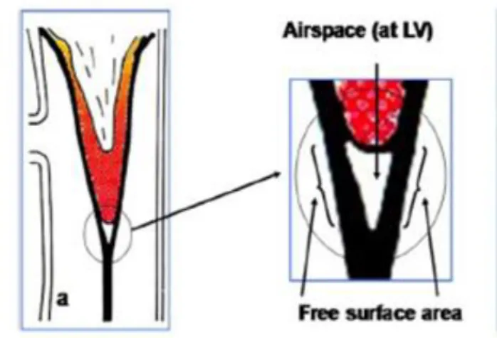
As shown by radiographic studies, it is a common fallacy that when the liner collapses beneath the teat it completely obstructs the vacuum supply. In reality, the teat tip is exposed to the vacuum for the whole duration of the milking because the closed liner never levels out completely and a small airspace exists beneath the teat during the d-phase of the pulsation cycle (Ardran et al, 1958). Teat in the closed liner with the magnification of the teat tip with the air space beneath it is shown in Figure 4. Mein et al. (2013) discuss that the origin of compressing force is the difference in pressure over the walls surrounding this airspace. Large surface that surrounds the teat barrel and is exposed to pressure difference across it amplifies the force in comparison to the small surface area beneath the teat. The degree of this pressure difference will determine the degree of compression (Mein et al., 2013).
Figure 4. Teat in the closed liner with the magnification of the teat tip with the air space beneath it (adapted from Mein et al., 2013).
Adequate liner compression will ensure effective pulsation and relive teat congestion and oedema (Mein et al., 2013). Zucali et al. (2008) found that higher compressive load was associated with the increased risk of teat-end hyperkeratosis of an experimental herd of 75 cows, while the duration of milking seemed to be even more important. Since the herd initially had a good teat-end condition it is possible that these effects would be even more pronounced if the experiment was performed on a commercial herd. Apart from liner characteristics that include liner wall thickness, mounting tension, rubber hardness and cross-sectional shape, teat size and shape and machine settings like claw vacuum have a great influence leading to a wide range of liner compressions applied by commercial liners (Mein et al., 2013).
2.3 Milk-flow
2.3.1 Milk-flow of a single milking
Mein & Reinemann (2007) divide milk-flow of a single milking session into three stages: stage of increasing milk-flow rate, stage of peak-flow milking rate and stage of low milk-flow rate. The authors use milk-flow curves obtained by Bruckmaier & Hilger (2001). The increasing milk-flow rate stage lasts from the beginning of the milking until the peak flow rate is reached (Mein & Reinemann, 2007). If pre-stimulation is not adequate and the milk ejection reflex is not activated prior to cluster attachment a transient drop in milk-flow occurs which
is seen as a bimodal flow-curve and the flow is classified as bimodal flow (Bruckmaier & Blum, 1996; Bruckmaier & Hilger, 2001). The peak flow rate is usually reached between 30 and 60 seconds from the cluster attachment. The swift increase in flow rate is dependent on the opening of the teat canal and there is little effect of machine settings like pulsation rate and ratio and vacuum level on the speed of this process. On the other hand, the peak-flow rate stage is affected greatly by machine settings while the anatomical features do not influence it since the diameter of the open canal is constant during this period. The magnitude of the peak-flow rate is not affected by the udder fill, but this period is prolonged by greater udder fill. The low-flow rate period is onset by the restriction of the milk-flow paths of at least one quarter (Mein & Reinemann, 2007). The restriction occurs above mouthpiece region due to the reduction in the teat sinus pressure related to the reduced volume of milk in the gland and is followed by repositioning (crawling) of the liner upwards on the teat. A complete occlusion of the milk-flow passage occurs as a consequence of teat tissue being drawn inside the liner (Mein et al., 1973b). The earlier during milking is the teat sinus emptied the higher-up is the crawling of the teatcup and the longer is the low-flow rate stage. This stage is affected mostly by the design of the cluster and the liner and their characteristics. Liners in poor condition, too light and unbalanced clusters lead to prolonged low-flow phase of milking (Mein & Reinemann, 2007). If the milk-flow rate from the udder to the teat cistern is lower than the flow rate out of the teat the flow is characterized as overmilking (Rasmussen, 2004). A slight increase in flow at the very end of milking happens due to machine stripping induced by the downward pressure that unblocks the flow pathway allowing cisternal milk effluence (Mein & Reinemann, 2007).
2.3.2 Milk-flow of a single pulsation cycle
In the course of one, single pulsation cycle three different flow stages have been identified. Expeditious increase in flow rate is followed by a short phase of maximum flow leading to a steep fall of about 60% in magnitude followed by further gradual fall of flow-rate. The flow reduction during a pulsation cycle occurs due to the accumulation of fluids in the teat interstitium as a consequence of exposure to vacuum. The resulting congestion and oedema decreases the effective diameter of the teat canal (Mein & Reinemann, 2014).
2.3.3 Milking time duration
Duration of milking is one of the crucial functional traits of dairy cows that is incorporated in breeding programmes (Macuhova & Bruckmaier, 2005) and it is
the main limiting factor of output of milking parlours (O’Callaghan et al., 2005). Innate milking rate shows broad variance between cows, while the within cow variance in single and between different lactations is very small (Baxter et al., 1950). Milking is a time consuming and labour intensive operation. As the average herd sizes are increasing and the milking installation is a major investment, interest in milking optimization and higher throughput is increasing (Edwards et al., 2014). Milking time is determined by the average milk flow and milk yield (Macuhova & Bruckmaier, 2005).
2.3.4 Average milk-flow rate
Factors that affect the average milk flow are the anatomical traits of the animal, management of the milking routines and milking machine properties and settings. The effects of the anatomical traits of the animal and the milking routines on milk flow and milking were previously discussed. The most important factors of the machine that have an effect on the average milk flow rate include the average claw vacuum, pulsation settings and liner compression (Mein et al., 2013).
A number of studies have shown that increased vacuum leads to higher flow rate and faster milking (Gregoire et al., 1954; Stewart & Schultz, 1958; Andreae, 1963; O’Callaghan et al., 2005; Ipema et al., 2005) with an increased stripping yield due to liner crawling up the teat (Smith & Petersen 1946; Baxter et al., 1950; Clough, 1963; Smith et al., 1974). In a more recent study by Macuhova & Bruckmaier (2005) with the higher vacuum level a tendency for a higher average milk flow rate and shorter machine-on time was seen with no effect seen on residual milk. The study was performed with a VMS system meaning that all cows were not milked in equal intervals or equal frequencies during the day. Unlike previously mentioned studies in which cows were milked twice per day the study by Macuhova & Bruckmaier (2005) does not report milking frequency which could possibly explain the reported results. Apart from the milking frequency a major difference in VMS, compared to parlour milking, is that the milking is performed and monitored on a quarter level. VMS monitors flow rate of each udder quarter and detaches teatcups individually, when a pre-determined flow rate is reached. It is possible that the milking regulated on a quarter level resulted in more efficient milking with minimal strip yield.
Increasing the rate of pulsation increases the average and peak milk flow rate but the magnitude varies considerably between animals with greater effects on slower milkers and at a lower set vacuum level (Steward & Schultz, 1958; Thiel
et al., 1966). On the other hand, studies performed by Schmidt et al. (1963) and Thomas et al. (1991) found no significant differences in the average flow rate at different rates of pulsation. Since the rates used in latter two studies were greater it can be concluded that the effect is seen only when comparing low to medium frequencies, while increasing the rate above 50-60 cycles shows no considerable effect (Thomas et al., 1991). As previously discussed, the flow rate during a single pulsation cycle decreases due to congestion of the teat interstitium. For this reason the increase in the pulsation rate will increase the average flow since the open phase of the liner is shorter which in turn shortens the fast flow-reduction phase of the single pulsation cycle (Mein & Reinemann, 2014). Widening the pulsation ratio by reducing the collapsed phase of the liner compared to the open or expanded phase leads to higher average flow rates and shorter milking times. Wide pulsation ratio with a moderate rate is most favorable for optimized milking (Smith & Petersen 1946; Andreae, 1963; Clough, 1963; Thomas et al., 1991).
When liner compression applied to the teat is lowered the flow rate follows up to the point at which the liner is unable to collapse and the flow is continuous. The flow-rate reduction occurs due to modification of the magnitude and duration of the initial peak. The effect is more pronounced at lower pulsation rates since at the higher rates the low-flow period is already reduced (Mein & Reinemann, 2014).
2.4 Vacuum
2.4.1 System vacuumWhile the milking machine is operational it is impossible to maintain an even vacuum level throughout the system. The existence of the vacuum gradient facilitates air flow toward the vacuum pump. The system is designed to minimize this gradient in all air and dual air and milk flow pipelines (Hall & Nordegren, 1968). Normally, the working vacuum in the system is between 40 and 50 kPa, with low-level installations utilizing lower vacuum levels (Akam et al., 1989).
In the course of the routine milking air is admitted into the system at various points. In order to ensure proper function of the milking machine this air influx has to be compensated in order to avoid vacuum drops along the system. If the volume of admitted air is greater than the effective reserve a drop in system vacuum will be seen (Brazil & Britten, 2001). The effective reserve is the
amount of air that can be admitted in the system while maintaining the vacuum within 2 kPa (ISO, 2007a).
2.4.2 Receiver vacuum
Both ISO recommendations and American Society of Agricultural Engineers (ASAE) standard specifications state that to ensure vacuum stability of the system vacuum drop in the receiver and its immediate vicinity should not exceed 2 kPa during a course of milking, including cluster manipulation, liner slips and cluster fall-offs. Measurement of the receiver vacuum stability can determine whether the milkline instability is caused by slugs or by inadequate vacuum production or regulation. The receiver vacuum measurement is not necessary if the milkline vacuum measurement meets the requirements (NMC, 2014; Reinemann et al., 2001b; ISO, 2007b; Reinemann et al., 1996a). It should be noted that the mentioned recommendations are proposed by the international standards for validation of machines that are constructed in the accordance with those standard.
2.4.3 Milkline vacuum
The nominal vacuum in the milklines is adjusted based on the desired average claw vacuum and it is dependent on the average vacuum drop measured according to ISO 5707:2007 standard (ISO, 2007b). A stratified flow where air flows uninterruptedly above the flow of milk is desired at all times. If “slugs” of milk, that occupy the whole cross-section, develop in the milkline a passing vacuum drop greater than 2 kPa occurs that is resolved as soon as the slug reaches the receiver. Sporadic slug development is unavoidable and it is acceptable to up to 5% of the milking time (NMC, 2014; ISO, 2007b; Reinemann et al., 1996a).
Reinemann et al. (1993) concluded that by increasing the slope of milklines the hazard of “sluggish” flow is reduced, with the length of the milkline having little effect. The study compared slopes of 0.5, 1 and 2 % with line lengths of 29 and 12m. Flow rate was adjusted in order to mimic peak flow rate of 4.5 l of liquid/min from each milking station. Both steady air admission, with a rate of 10 l/m of air per 4.5 l/m of liquid, and sudden admission, from 50 l/m to 500 l/m per slope, were tested. They found that with vacuum drops below 2 kPa in milklines slugs did not develop nor did it provoke changes in vacuum pattern of clusters. Sudden air admission, usually associated with cluster manipulation and fall-offs, presented a higher risk for slug development than a constant air influx
through vents and leaks. The authors took into account factors like physical properties of the liquid, the density, viscosity and foaming, which were adjusted to mimic warm milk. Furthermore they reproduced challenging conditions in form of high milk-flow rate and air admission rate with both sudden and steady air ingress mimicking conditions occurring during a usual milking.
2.4.4 Cluster vacuum
Considerable amount of air enters the system during cluster attachment and fall-offs. Brazil & Britten (2001) tested the amount of admitted air in a dry test with air flow meter regulating the air volumes in order to test the effect of different cluster design and estimate the volume of air admittance during cluster manipulation. The authors found that if the air is being admitted only through one teatcup the diameter of the short milk tube is the main determinant of the volume of air that enters the system while the diameter of the claw outlet and the long milk tube is the main determinant if more than one teatcup is leaking air. Even though the study design provided good control of the air flow rate focusing on only one variable the variance in the milk-flow rate between cows and the number of milkers and the attachment routines can introduce large variations and the application of the results to a realistic milking in a parlour could be challenging.
2.4.4.1 Claw vacuum
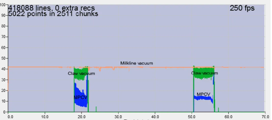
The magnitude of system vacuum is adjusted in order to provide the desired claw vacuum during peak-flow period (ISO, 2007b). The design of the milking system affects the rates of milk flow and air admission which affect the claw vacuum. Reinemann et al. (2007) performed wet and milking-time tests of the claw vacuum in milking parlours in Wisconsin. However, the authors do not state the number of parlours, cows or milkings that were measured. Only averages of vacuum are reported measured at eight parlours. In addition milk-flow curves were obtained in order to elucidate changes in claw vacuum depending on different flow stages. It was found that, upon cluster attachment, the claw vacuum increased to the system vacuum following a rapid decrease as soon as the milk-flow started and the higher the flow rate the lower the claw vacuum dropped. As the flow rate decreased, toward the end of milking, the claw vacuum increased. Even though very little air was admitted into the claw and the vacuum fluctuations were low and followed the pulsation cycle, the authors recognizes that a liner slip can introduce a large volume of air resulting in a rapid, transient drop in the claw vacuum (Reinemann et al., 2007). While the milking-time and
wet tests compared well, there was a considerable variation between farms when vacuum at different milk-flow rates was compared likely due to different machine characteristics. From this study it can be deduced that if different configurations of an installation are compared a wet test is a better option due to the elimination of the cow variance and accurate control of the flow-rate.
Measurement of claw vacuum is the most direct measurement of the effect of the system on the animal. Recommendations for the magnitude of average claw vacuum during peak milk flow differ between guidelines in North America, by the National Mastitis Council (NMC, 2014), that advise it to be maintained between 36 kPa and 42 kPa and European countries that mainly consider ISO (2007b) recommendations of 32 to 42 kPa. The average is calculated from a 5 to 20 seconds window during the peak flow. This discrepancy in recommendations reflects the competing goals and priorities. With larger farm size it is more common to opt for a higher claw vacuum that increases the speed of milking at a cost of a less gentle and less complete milking, while smaller farms will put more emphasis on the completeness and gentleness of milking at the cost of time efficiency (Reinemann et al., 2007). No allowable limits of fluctuations of claw vacuum are given in current international standards. While Reinemann et al. (1996a), referring to the NMC’s guidelines, state that the average vacuum fluctuations should be less than 7 kPa and less than 10 kPa in a low-line and high-line milking systems respectively, the current guidelines published in 2014 (NMC, 2014) do not include this recommendation.
2.4.4.2 Mouthpiece chamber vacuum (MPCV)
Borkhus & Rønningen (2003) performed a study during eight milkings of ten cows with an aim to describe the pattern of the MPCV during different flow stages of the milking and examine effects of the liner type, pulsation ratio, morning to evening milking, milk flow rate and teat size. In addition teat penetration inside the liner was measured throughout the milking. Authors propose that the MPCV is a result of a counterbalance of air volume leaking through the mouthpiece lip and vacuum entering past the teat in the liner barrel. The study found that three distinct phases in MPCV can be seen during one whole milking. During the let-down phase the MPCV increased after which it either stabilized or decreased gradually during the peak flow phase. The gradual decrease coincided with the progressive teat penetration deeper inside the liner. During this phase vacuum fluctuations were small and synchronized with the pulsation. As the milking entered the low-flow phase the vacuum fluctuations and the MPCV increased which was accompanied by the deeper protrusion of
the teat inside the liner and a rise in short milk tube vacuum. All combinations of two different liner types and pulsation ratios of 60 and 70% were tested for both morning and evening milking. Lower bore liners with larger mouthpiece opening, evening milking and higher milk-flow rate resulted in lower MPCV. Long and wide teats generally led to lower MPCV but teat penetration depth into the liner, rather than teat dimensions, determined the MPCV (Borkhus & Rønningen, 2003). Newman et al. (1991) described similar vacuum patterns during different flow stages with wide bore liners and lower milk-flow rate giving higher values of MPCV. Despite the small number of animals in the mentioned studies, ten and six respectively, the similarity of the findings of the studies that were more than a decade apart suggests that their conclusions can be accepted.
Rønningen & Rasmussen (2008) proposed that mouthpiece chamber vacuum (MPCV) measurements should be included in the milking-time tests. Vacuum recordings were collected during routine maintenance by service technicians from 2077 cows on 265 farms. In addition a visual assessment of teat dimensions was performed while the data regarding udder health and milk quality were obtained from the herd health databases. The authors found that MPCV was highly variable in the herd and that a medium MPCV during the peak flow period, between 10kPa and 30kPa, was highly negatively correlated with mastitis. It is thus desirable that the percentage of cows in the herd milked within this range is high. Teat end vacuum and irregular vacuum fluctuations obtained from short milk tube vacuum records were also assessed but yielded no statistical significance for udder health. Even though the authors measured only one milking per cow according to Rønningen (2004) the measurement is highly repeatable for a cow between different milkings. The effect of teat dimensions on MPCV was in line with the findings of Borkhus & Rønningen (2003). The large sample size and the fact that the field measurements were performed during routine milkings add value to the study compared to the experimental ones which are often hard to compare and apply to standard milking conditions.
2.4.5 Vacuum fluctuations
The difference between a minimum and a maximum vacuum value in a whole pulsation cycle is a vacuum fluctuation (O’Callaghan et al., 2001). The fluctuations can be regular occurring due to the pulsation cycle or irregular occurring due to a malfunction or bad design of the milking system. According to a review by Cowhig (1968) irregular vacuum fluctuations can be divided into three types. Type 1 fluctuations affect the whole vacuum installation or its large
part and are caused by inadequate vacuum pump capacity, faulty vacuum controller, excessive air leaks and pipeline obstructions. Type 2 fluctuations are localized in milk tubes and pipelines and are caused by the hydrostatic pressure of milk flowing from the clusters while the type 3 fluctuations, also caused by the milk flow hindering air flow in the vacuum system, affect the teatcup liner. Vacuum fluctuations can reduce the milking rate thereby increasing the milking time and increase the frequency of teatcup falling off with possible effects on udder infection and health. The instability of the liner and the disruption of its seal with the teat introduce air inside the milking system which leads to irregular vacuum fluctuations in the liner, the short milk tube and the claw chamber (Thiel, 1978). Davis & Reinemann (2001), based on a study on 80 cow milkings, propose two categories of irregular vacuum fluctuations, defined by the magnitude and rate needed to induce reverse pressure gradient, considering vacuum in the claw chamber. They define irregular vacuum fluctuations 1 (IVF1) as vacuum drops of ≥21kPa and with a rate of fall that is ≥ 100kPa/s and irregular vacuum fluctuations 2 (IVF2) as vacuum drops of ≥14kPa range with a rate of fall that is ≥ 56kPa/s. The method of determining reverse pressure gradient was not given in the study, but referred to a previous study performed by the authors.
O’Callaghan et al. (2001) found that vacuum losses were generally lower in low-level milking systems compared to mid-level ones. Authors also found that narrower bore of long and short milk tube led to a higher vacuum loss in mid-level system while both systems had higher loses when alternate pulsation was used. Alternate pulsation also showed increase in the vacuum fluctuations with increasing flow while the same was not evident with simultaneous pulsation. The study was performed as a wet test with an artificial teat. The choice of a method provided a better control of flow rate than a milking-time test would. An older study by McDonald & Witzel (1968) found, on the contrary, that simultaneous pulsation settings provoked higher vacuum fluctuations than the alternate. This discrepancy could be explained by the much narrower diameters of liners (9-12 mm compared to 19-21mm lower bore diameter) and smaller claw bowl capacity (19-78 ml compared to 150-420 ml) used in this study compared to the study by O’Callaghan et al. (2001). Also McDonald & Witzel (1968) were measuring fluctuations while milking cows which, as previously discussed, limited the control of the flow rate and could have affected the results. With increasing flow rate and decreasing diameter of claw inlets and outlets, claw volume and long milk tube diameter the magnitude of fluctuations increased. In addition, McDonald & Witzel (1968) examined the effect of air inlet position and found that placement of the inlet in each liner, near the teat end, reduced fluctuation
with less air needing to be admitted compared to the placement of air inlet in the claw. The study used only four animals and the number of milkings recorded was not given. Furthermore, no statistical analysis of the data was presented leading to a limited value of any conclusions made by the authors.
2.4.6 Vacuum and udder health
A study by Langlois et al. (1981) showed that higher vacuum levels, in the order of 51 kPa, could increase the prevalence of mastitis and result in poorer teat scores when compared to milking vacuum of 34 and 42.5 kPa. On the other hand an older study by Schmidt et al. (1963) showed no increase in mastitis rate at vacuum levels as high as 81 kPa. Olney & Mitchell (1983) found no increase in somatic cell count in cows milked at 70 kPa not even when exposed to 5 minutes of overmilking. A possible explanation for this discordance could be that in the study by Langlois et al. (1981) cows used in the experiment were in the first week of lactation while in the latter two experiments cows were past peak lactation, 2 months or more from the beginning of lactation. Moreover, Langlois et al. (1981) discuss that many different milkers including 20 different students were milking the experimental animals meaning that the milking practices could have been sub-optimal and lead to effects on udder health. Hamman et al. (1993) and Engelke et al. (1995) found that with the increasing vacuum the severity of the machine-induced oedema, evident by increased teat thickness, incremented.
A field study by Beckley & Smith (1962) and experimental studies by Stanley et al. (1962) and Cowhig & Nyhan (1967) indicated that unstable vacuum, in a form of vacuum fluctuations, significantly increased mastitis incidence determined by the California mastitis test (CMT). The authors do not specify whether they monitored cyclic or irregular vacuum fluctuations. Nevertheless, since authors were studying lower vacuum pump capacities of milking installations which induce irregular vacuum fluctuations, it can be concluded that the effects can be contributed to the latter (Nyhan, 1968). Thiel et al. (1973) found that neither high cyclic nor high irregular vacuum fluctuations increased udder infection, but combinations of different magnitudes of both did. On the other hand O’Callaghan et al. (1976) and O’Shea et al. (1976) report that neither the large cyclic or irregular vacuum fluctuation or the combinations of both increase mastitis rate and propose liner slips as the single most important cause of increased mastitis incidence. Thompson et al. (1978) suggested that any combination of vacuum occurrences, most often a liner slip, that induces swift airflow toward the teat canal, facilitating microbial entrance inside the gland,
increases infection rate. Studies by Schmidt et al. (1964) and Olney et al. (1983) have not found any difference in mastitis occurrence due to vacuum fluctuations. Unlike previously mentioned studies the latter two have not introduced a bacterial challenge to udders of experimental animals. It is possible that the studies by Schmidt et al. (1964) and Olney et al. (1983) were too short, 25 and 12 days respectively, to observe mastitis incidence without an introduced bacterial challenge.
Vacuum of a milking machine installation is a dynamic parameter that changes throughout the milking and along different parts of the machine. Due to its possible harmful effect on the udder health and the efficiency of the milking process vacuum levels of different parts of the machine, as well as their changes during the milking session, need to be understood and controlled within pre-determined reference values.
2.5 Measuring vacuum
Vacuum system of milking machines is tested regularly to insure proper function and avoid detrimental effects on udder health. According to the ISO 3918:2007 standard milking machine tests can be dry test that are done on a working milking machine without any liquid, wet tests done on a working machine with milking simulated with an artificial teat and water to mimic milk flow, milking-time tests that are performed during milking of live animals and cleaning-milking-time tests done on a milking machine during the cleaning cycle (ISO, 2007a). Milking-time tests are not required by the ISO 6690:2007 standard when validating milking machine installations (ISO, 2007c). The National Mastitis Council (NMC) (2014) proposes milking-time tests as means of evaluating vacuum and provides guidelines and methods for testing. Since milking-time tests are not proposed by international standards it can be assumed that they are not performed routinely. All the scientific studies into milking-time testing identified in the literature are considering individual measuring points and a comprehensive enquiry into the methodology of a milking-time test of the whole system was not found.
Testing the equipment in laboratory conditions and without attachment to the animals has its advantages, allows better control over the complex system and permits sequestration of variables (Amirante et al., 2005). Flow rate is determined more precisely and the cow variation is eliminated as well (Reinemann et al., 2007). Nonetheless, it is difficult to mimic milking conditions
without a live animal and verification and application of the data to the realistic condition in the milking parlour during actual milking can be challenging (Amirante et al., 2005). The milking time tests measure vacuum under normal conditions in the milking parlour and allow for the interaction of milker, cow and machine to be assessed. They represent the most direct method to validate system vacuum of the milking machine, both the aptitude of vacuum production and vacuum regulation throughout the system (Reinemann et al., 2007). It is recommended to perform milking-time testing before a new milking system is introduced, before and after major modifications to an existing system are made and if the performance of an operational system is unsatisfactory (Reinemann et al., 1996a). In order to assess the system adequately accurate measurements of vacuum at several points along the system need to be obtained (Reinemann et al., 2007).
2.5.1 Vacuum measuring equipment
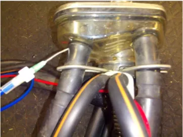
A vacuum measuring system is comprised of vacuum transducers connected to measuring points with connectors, fittings and tubes and a digital electronic element receiving and storing the data for further analysis. Since the fittings and tubes can cause error in measurement by damping the vacuum fluctuations their volume needs to be minimized (Reinemann et al., 1997). The presence of fluids in the connecting system is a major source of error hence the needles and connectors have to be positioned out of the milk stream and they should be able to drain freely. Any liquid that might be present in the tubes should be removed prior to measurements. Longer tubes with a bigger diameter will draw more water into the system (Reinemann et al., 2001b). The length of tubes should be limited to 2 meters. It is recommended that no needles are used at measuring points in the receiver and the milklines. If needles are used they should be either 12 or 14 gauge. The connection to the claw bowl should be made either without needles, with a tee piece inserted into the long milk tube, or by penetrating the short milk tube with a 12 or 14 gauge needle (Reinemann et al., 1996a). In a study by Borkhus & Rønningen (2003) the connection to mouthpiece chamber was made with a steel pipe inserted in the liner wall.
The accuracy of the vacuum measuring system is limited by the response rate (kPa/s) and the sampling rate or frequency (Hz). In order to accurately detect all vacuum changes the response rate has to be higher than the maximum rate of change of vacuum in the system and the sampling rate has to be faster than the fluctuations that are occurring during milking. The response rate is mostly affected by the connecting system and presence of fluid in the tubes (Reinemann