Supporting Information
Plasmonic Enhanced Graphene Oxide-based Aquatic Robot for Target
Cargo Delivery
Yuanyuan Yang1,# , Yanting Liu1,#, and Yajing Shen1,2,*
1 Department of Biomedical Engineering, City University of Hong Kong, 999077 Hong
Kong SAR, China
2 CityU Shen Zhen Research Institute, Shenzhen, 518000, China
# Equal contribution to this study *E-mail: [email protected]
Supplementary Figures
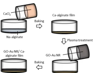
Figure S1. The fabrication process of GO-Au NR/Ca-alginate robot. 1.5 ml 2 wt% Na-alginate is poured into a plasma-treated dish and dried in the oven for 1 hour. Then 2 wt% CaCl2 solution is added to the dried Na-alginate film forming Ca-alginate hydrogel
and dried for another hour. After plasma treatment on the hydrogel surface, 5 ml GO-Au NR solution is added on the top and dried for 5h. Such operation repeats one more time, and the robot is got by peeling off and cut into different shapes for specific function modes.
Figure S2. COMSOL simulation of electric field enhancement. The simulation of a single Au NR shows an enhancement of the electric field on the gold nanorod surface by the 808 nm wavelength incident light (incident angle: 60°).
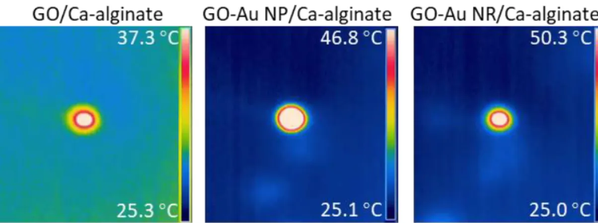
Figure S3. The temperature change of GO/Ca-alginate, GO-Au NP/ Ca-alginate, and
GO-Au NR/ Ca-alginate film after exposed to 3 W/cm2 NIR light for 1s. The sample
with Au NRs owns the largest temperature variation about 25 °C which is 2 times the GO/Ca-alginate’s temperature variation. Compare with Au NPs, the Au NRs exhibit higher photothermal efficiency due to the unique longitudinal SPR.
Figure S4. Schematic of Au NPs’ plasmon oscillation. During light exposure, the electron oscillation in one Au NP will lead to the electron oscillation in the adjacent Au NP, which are then coupled together forming SPR to enhance the local electric field. Due to the isotropic shape, the Au NPs only have single SPR mode.
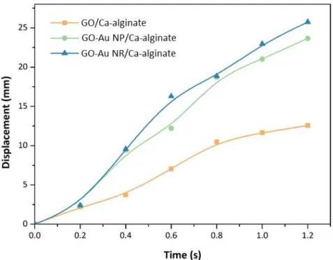
Figure S5. The displacement of GO/Ca-alginate, GO-Au NP/Ca-alginate, and GO-Au NR/Ca-alginate robot during the actuation by 3 W/cm2 NIR light. Since higher
temperature variation during light exposure will lead to a higher surface tension gradient, the GO-Au NR/Ca-alginate robot shows the highest motion speed.
Figure S6. Light-manipulated assembly of robots implemented by selectively actuating the robots. Different assembly modes are formed by adjusting the light exposure area, showing great potential for the complex architecture’s construction applications.
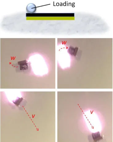
Figure S7. The high actuating strength enables the robot's weight loading ability. The robot can load weight more than 100 times of itself while still implementing effective and controllable linear and rotation locomotion.
Figure S8. The robot owns good obstacle crossing ability exhibiting high actuating strength. For illustration, polystyrene beads (diameter: 0.5 ~ 1 mm) are placed on the water surface acting as obstacles. With NIR light actuation, the robot approaches the obstacles and break over within 1s.
Figure S9. Leaching test of the Au NRs in different buffers over times. The test is carried out in buffers with different pH value including 2-(N-morpholino) ethanesulfonic acid (MES) buffer (pH=5) and tris (hydroxymethyl) aminomethane (TRIS) buffer (pH=7 and 9). To measure the leaching of Au NRs, the GO-Au
NR/Ca-alginate robot (2 mm×2 mm) is placed in 5 ml MES (pH=5), TRIS (pH=7), and TRIS
(pH=9) buffer separately. The 3 kinds of buffer solution samples (100 µL) are then collected after 1 h, 12 h, 24 h, 2 day and 3 day. Compared with the absorption spectrum of Au NRs, the absorption intensity of (a) MES buffer (pH=5) (b) TRIS buffer (pH=7) (c) TRIS buffer (pH=9) is almost 0, indicating that Au NRs is not leached owe to the good electrostatic interaction between Au NRs and GO sheet.
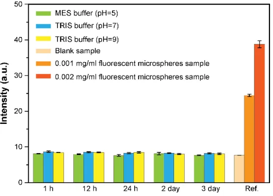
Figure S10. Leaching test of the cargos in different buffers over times. The fluorescent
and TRIS (pH=9) buffer separately. The 3 kinds of buffer solution samples (100 µL) are then collected after 1 h, 12 h, 24 h, 2 day and 3 day. The fluorescent spectrum of collected buffers samples after 1 h, 12 h, 24 h, 2 day and 3 day is measured. The fluorescent intensity of buffers is closely equal to blank samples without fluorescent microspheres. The results show that the cargos are embedded in the hydrogel network without leaching, indicating the good stability of the Ca-alginate layer.
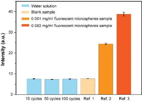
Figure S11. Leaching test of the cargos over various actuating cycles. The fluorescent microspheres loaded robot (2 mm×2 mm) is placed in 5 ml water solution and actuated by 3 W/cm2 light exposure for 10, 50, and 100 times. The corresponding water samples
(100 µL) are collected and the fluorescent intensity of collected water samples is measured. The fluorescent intensity of robot surrounding water is closely equal to blank samples that do not contain fluorescent microspheres. The results show that the embedded molecules do not leak from Ca-alginate hydrogels during the actuating process at various times.
Figure S12. Benefited from the effective photothermal working mechanism, robots with different shapes all exhibit high motion controllability. (a) Linear motion of rectangle shape robot. (b) Rotational motion of rectangle shape robot. (c) Linear motion of the hexagon shape robot. (d) Rotational motion of hexagon shape robot.
Figure S13. Investigation of the released efficiency. To investigate the released efficiency of the cargo-loaded module, the fluorescent intensity is recorded representing
the amount of the cargo. The robot is firstly placed with microspheres embedded layer downward that almost no fluorescent microspheres are observed. After adding the sodium citrate, the cargo-loaded layer is destroyed and peels off, at which time the fluorescent intensity will reach the peak point. Then the microspheres release and diffuse causing the decrease of fluorescent intensity in the picture. (a) To investigate the influence of sodium citrate’s concentration in the release efficiency, the robot is placed in 3 ml water solution and 1 ml 35 mM, 55 mM, and 75 mM sodium citrate is added to the water solution separately. According to the fluorescent intensity data, the higher concentration of sodium citrate could lead to shorter peeling off time of Ca-alginate layer and higher releasing speed. (b) To investigate the influence of temperature in the release efficiency, the robot is placed in 3 ml water solution with different temperatures, i.e. 25 ℃, 50 ℃, and 75 ℃. 1 ml 55 mM sodium citrate is added to the solution separately. According to the fluorescent intensity data, the higher temperature could lead to shorter peeling off time of Ca-alginate layer and higher releasing speed of cargos. (c) To investigate the influence of robot’s shape in the release efficiency, the robot is cut into different shapes, i.e. rectangle, triangle, and pentagon. Robots with different shape are placed in separate dishes containing 3 ml water and 1 ml 55 mM sodium citrate is added to the dishes separately. According to the fluorescent intensity data, the shape of robots has little influence on the release efficiency. (d) To investigate the influence of robot’s amount in the release efficiency, different number of robots (i.e. 1, 2, and 3) are placed into 3 dishes which contains 3 ml water solution. Then 1 ml 55 mM sodium citrate is added to the dishes separately. According to the fluorescent intensity data, the amount of robot has little influence on the peeling off time of cargo-loaded layer. The group with a larger robot number owns a higher slope of fluorescent intensity after peeling off because of the larger cargo amount. Therefore, the amount of robots has little influence on the release efficiency of cargo-loaded layer.
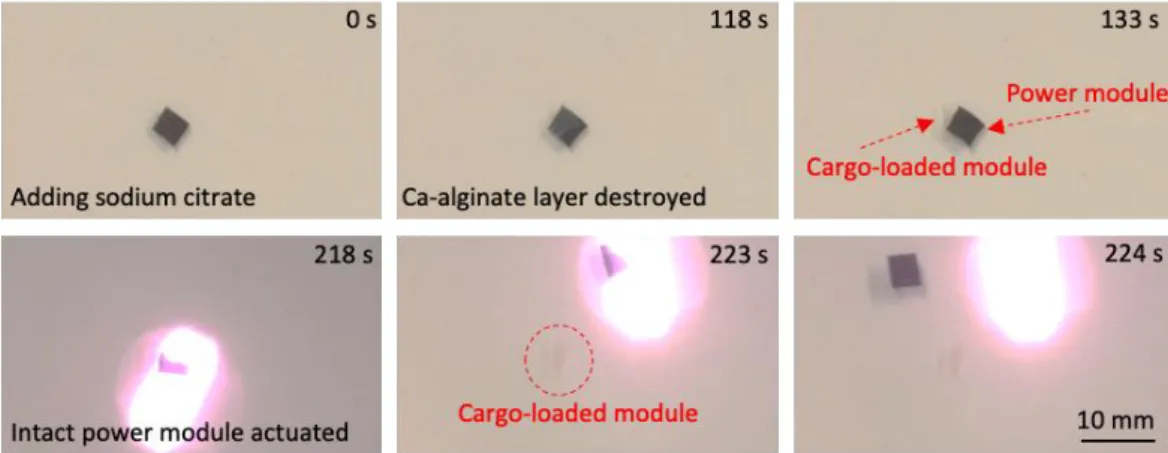
Figure S14. Collection of power module after cargo release. After adding sodium citrate, the Ca-alginate layer is destroyed and peels off from GO-Au NR layer for cargo release. The power module GO-Au NR layer is intact that can be actuated for collection.