RF-EVB manual V1.21
1. Brief introductionRF-EVB is an evaluation board which is used to test the RF COB modules from HOPERF. Simple and practical way of demonstration lets users to understand the corresponding COB module of radio frequency characteristics easily and intuitively. This board has moderate size, simple operation, easy to carry these advantages which are suitable for R&D evaluation and out door distance evaluation
2. Functions
Working voltage:
battery:3 AA 1.5V battery(AA size battery) DC voiltage:3.6 V~5.5 V Support modules: RFM01/02/12B; RFM22B/23B/31B/42B/43B; RFM63W/64W/65W/66W/67W/68W/69W/69HW; RFM68CW/65CW/69CW/69HCW; RFM92/93/95/96/97/98;
If you want more modules used on this EVB ,you can update the hardware of EVB, For more details please pay attention to www.hoperf.com.
Simple instruction:press the trigger button to transmitter status, lose the trigger button to monitor status;
Current test: via the current test interface, you can test the transmit/receive current easily; Identify the model automatically and demonstrate corresponding functions.
Working abnormal condition remind
Support hardware update: customers can upgrade EVB hardware to test more models by this annual. Typical version of the hardware you can refer to website of HOPERF.
3. Hardware layout and description of interfaces.
Frontage layout of RF-EVB is the figure on the right
figure1 EVB layout figure
item functions
1 Power switch
2 Power supply indicator: LED
3 RFM_COB working current test lead
Note: resistance beside or inside must be move away
4 Error/abnormal indicator LED
5 The factory test mode status indication LED
6 Work normal status indication LED
7 Launches trigger buttons
8 buzzer receive effective signals
9 Receive status indicator LED
10 Transmitter status indicator LED
11 Frequency band selection jumper
RF-EVB manual V1.21
Tel: +86-755-82973805 Fax: +86-755-82973550 E-mail: [email protected] http://www.hoperf.com
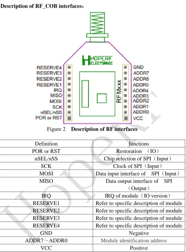
Description of RF_COB interfaces:
Figure 2 Description of RF interfaces Definition functions POR or RST Restoration (IO)
nSEL/nSS Chip selection of SPI(Input) SCK Clock of SPI(Input)
MOSI Data input interface of SPI(Input) MISO Data output interface of SPI
(Output)
IRQ IRQ of module(IO version) RESERVE1 Refer to specific description of module RESERVE2 Refer to specific description of module RESERVE3 Refer to specific description of module RESERVE4 Refer to specific description of module
GND Negative
ADDR7~ADDR0 Module identification address VCC Positive
RF-EVB manual V1.21
4. Instruction Description embed 3 AA battery; inset COB module;
The power switch toggle to ON,LED lights up at this time which shows the power supply normally;
Under normal working circumstance , Normal LED rights up;
Modules in received or transmitted/ received status, when Rx_LED is lighten which shows the module is in the receiving state
When modules in single transmit status, Rx_LED turned off which shows the module is in stand-by status, wait until the trigger switch and turn to transmit status. i. Press the button to transmit, If the module is transmitted/ received or single
transmit module, the Tx_LED lights will be lighten up regularly which shows the module is in transmit status. When lose the button, the module stop transmit and Tx_LED lights turns off.
ii. Press the button to transmit, If the module is single receive module, the error_LED light will be lighten up and error.
If there are two EVB, one of which is in a state of normal emission and the other one of which is under a state of normal received, the buzzer of the receiver will ring until the transmitter stop sending.
5. Transmit/receive message format of EVB
Content of the message
Definition Preamble SYNC. Word
HopeRF Series Message Length 5 Bytes 2 Bytes 14 Bytes 7 Bytes content 0xAAAAAAAAAA 0x2DD4 “HopeRF RFM COB” “RFMxxxx”
RF parameters
definition Parameters remarks Centre frequency 315/434/868/915MHz Can be set Transmit deviation +/-35KHz
Wireless speed rate 2400bps Coded format NRZ
Frame time ≈100ms For examples:
RFM69H-S2 module:data 0xAAAAAAAAAA2DD4+”HopeRF RFM COB”+”RFM69HS”; RFM69-S2module: data 0xAAAAAAAAAA2DD4+”HopeRF RFM COB”+”RFM69-S”; RFM23B-S2 module:data 0xAAAAAAAAAA2DD4+”HopeRF RFM COB”+”RFM23BS”
RF-EVB manual V1.21
Tel: +86-755-82973805 Fax: +86-755-82973550 E-mail: [email protected] http://www.hoperf.com
LoRa Modulation
Content of the message
Name HopeRF Series Message Length 14 Bytes 7 Bytes content “HopeRF RFM
COB”
“RFMxxxx” For example:
RFM92-S module:Date ”HopeRF RFM COB”+”RFM92-S”; RFM95-S module:Date”HopeRF RFM COB”+”RFM95-S”; RFM96-S module:Date”HopeRF RFM COB”+”RFM96-S”;
Parameter settings
Name Reference value remarks Center frequency 315/434/868/915MHz Can be set
SpreadingFactor 9 BandWidth 125KHz CodingRate 4/5 CRC Enable PreambleLength 12 + 4 Byte HeaderMode ExplicitMode 6. Notes and application tips
Error LED shows kinds of effective circumstance
1) No RF module in it, it will work normally when you inset the module
2) Not choose specific work frequency, frequency increase insert selection jumper cap is solved
3) Without the work status, such as: single receiving module, there is no emission features
4) Frequency is not allowed. For example, RFM63W just work in the frequency of 868MHz and 915MHz, if you set the working frequency to 433MHz,EVB will shows error
5) The modules work abnormally, please contact our engineers of our company.
6) Insert the RF module, but there is no short circuit current test interface which can lead to the mistakenly to upgrade mode. Insert short current test end, when the power is back this problem can be solved.
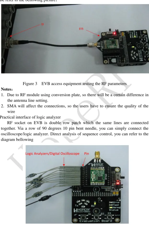
Easy and convenient access to the RF performance assessment instrument
With SMA connector, you can use the SMA for wiring, simple and direct access to the RF performance assessment instrument.
RF-EVB manual V1.21
Please refer to the bellowing picture:Figure 3 EVB access equipment testing the RF parameters
Notes:
1. Due to RF module using conversion plate, so there will be a certain difference in the antenna line setting.
2. SMA will affect the connections, so the users have to ensure the quality of the wire
Practical interface of logic analyzer
RF socket on EVB is double row patch which the same lines are connected together. Via a row of 90 degrees 10 pin bent needle, you can simply connect the oscilloscope/logic analyzer. Direct analysis of sequence control, you can refer to the diagram bellowing
Figure 4 EVB with row needles connecting logic comparison with RF module sequence control analyzer
RF-EVB manual V1.21
Tel: +86-755-82973805 Fax: +86-755-82973550 E-mail: [email protected] http://www.hoperf.com
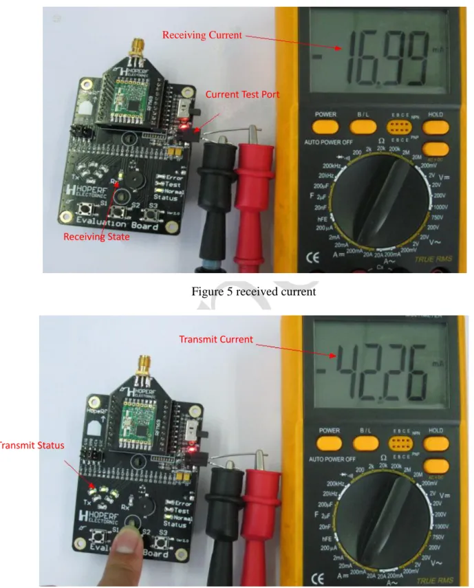
test kinds of the working power consumption
To evaluate the modules can meet the specifications or not, you can test the RF received current, transmit current .For more details, you can refer to bellowing pictures.
Figure 5 received current
Figure 6 transmit current Receiving State
Receiving Current
Current Test Port
Transmit Status
Transmit Current
RF-EVB manual V1.21
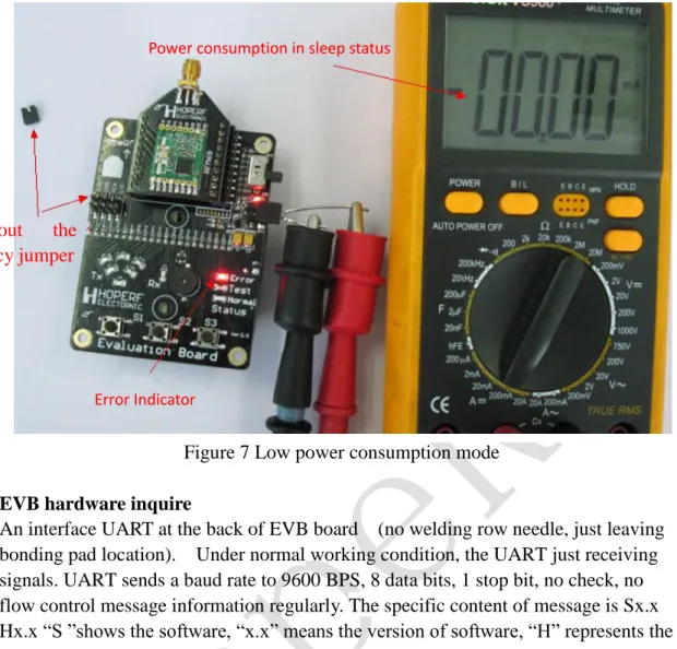
Figure 7 Low power consumption mode
EVB hardware inquire
An interface UART at the back of EVB board (no welding row needle, just leaving bonding pad location). Under normal working condition, the UART just receiving signals. UART sends a baud rate to 9600 BPS, 8 data bits, 1 stop bit, no check, no flow control message information regularly. The specific content of message is Sx.x Hx.x “S ”shows the software, “x.x” means the version of software, “H” represents the hardware and “x.x”means the version of hardware. So you can determine whether to upgrade your software or not by the hardware version.
Figure 8 back of the UART interface and the corresponding display effect
Via the PC "start - > programs - > accessories - > communication - > super terminal" to establish a connection. Settings are as follows
Power consumption in sleep status
Error Indicator
Pull out the
frequency jumper
Software and hardware Version
RF-EVB manual V1.21
Tel: +86-755-82973805 Fax: +86-755-82973550 E-mail: [email protected] http://www.hoperf.com
Step 1: establish a connection, name and select the icon, Then click "ok";
Step 2: set the connection equipment, select the COM and Setting the COM, then click "ok";
Step 3: set the communication parameters, Specific parameters are as follows:
Digits per second (B): 9600
Data bits (D):8 Parity (P): no
Stop bit (S): 1.
Data flow control (F) : no
click "application" and then "ok" to complete the setup.
Notes: baud rate should be set to 19200 when upgrade the hardware.
RF-EVB manual V1.21
Step 4: click the right red circle icon on the right toModify the attribute.
Step 5: select "Settings" and then click on the "ASCII Set (A) ".
Step 6:
1、 tick the box name ”line break as end of the sending line” and “local echo type character 2、 line delay should not be less than 20ms if not it will affect the upgrading software, 3、then click “confirm”
After that, the setting is finished and connect with UART of EVB and receive corresponding version information.
Step 7:
Click on the red circle icon to disconnect and then close the dialogue box. Before close, we always suggest that you save this Setting for your continued application.
RF-EVB manual V1.21
Tel: +86-755-82973805 Fax: +86-755-82973550 E-mail: [email protected] http://www.hoperf.com
upgrade firmware of EVB
The firmware upgrade of EVB can make more HopeRF rf module to be used on this EVB which is much more convenient for users evaluation. EVB firmware version information please pay attention to HopeRF website.
Based on the previous detection version which has introduced how to set up the super terminal connection,So what you need to do is repeatting the above process and change baud rate to 19200, after that to build a "HopeRF EVB Bootloader", then follow the belowing 3 simple steps to upgrade the firmware.
Step1:enter into upgrade
1.
EVB Power off to EVB and let the eight feets of RF modules ADDR0~ADDR7 to the ground, after That power on.(note: the power must not be cut When upgrading or it will cause unpredictable damage.
2. About 1ms later, Error、Test、Normal three lights on EVB lighten up which shows the firmware
enter into upgrade background program 3. Shown as the right figures;
4. UART connect with PC,and open the setting of Supper terminal “HopeRF EVB Bootloader”。
5.Tips as shown on the right figure
6. please pull the address line of short circuit tools to enter into background program repeatedly
conveniently
Step 2:wipe software
1. Under the super terminal interface, press "e" to wipe applications
Layer of software
2.working sketch is shown on the right;
3. Turn off the power of EVB,(the Power supply line of UART should be removed)
upgrading mode, 3 LEDs light together
8 ADDRESS PINs connect to GND
RF-EVB manual V1.21
Step3:Upgrade software
1、Turning on power of EVB again. As the software of App has been wiped so it can only upgrade background software without Address short circuit tools the connection of Supper terminal, you can refer to the figure on the right
2、 Under the super terminal interface, press the "u" form to Update software, refer to the picture on the right;
3、Click "send" in the menu bar, and select" Send a text file ", and then open the Upgrade TXT file, the file through the super Terminal to transmit, EVB is upgrading!
The file transfer is completed, please exit this connection, use the version to check the upgrade success or not. After the success of the upgrade, with version information query can see the correct version of firmware.
Notes:
1. EVB upgrade process, please do not interrupt or unplug connecting cable, so as not to cause irreversible damage when upgrading the EVB.
2. If upgrade failed, please power off and energized again, if enter the backend upgrade mode, you can still through the operation to restore the application layer operation; If could not enter the background update mode, the system program will be damaged, please contact HopeRF technical personnel for support.
3. The firmware upgrade requires technical knowledge background, so please do above process operation according requirements to avoid unrecoverable damage. 4. "line delay" is a must as EVB automatic update burn needs certain reaction time,
we suggest the time setting is 30ms not less than 20 ms,
5 Do not mistakenly to short circuit the positive of the battery while using address short circuit tools.
RF-EVB manual V1.21
Tel: +86-755-82973805 Fax: +86-755-82973550 E-mail: [email protected] http://www.hoperf.com
7. Schematic
RF-EVB manual V1.21
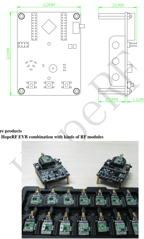
8. Product appearance size figure
9. More products
HopeRF EVB combination with kinds of RF modules
RF-EVB manual V1.21
Tel: +86-755-82973805 Fax: +86-755-82973550 E-mail: [email protected] http://www.hoperf.com
More related RF modules
Figure16 Development board for function test
RF-EVB manual V1.21
HOPE MICROELECTRONICS CO.,LTD
Add: 2/F, Building 3, Pingshan Private Enterprise Science and Technology Park, Lishan Road, XiLi Town, Nanshan District, Shenzhen, Guangdong, China Tel: 86-755-82973805 Fax: 86-755-82973550 Email: [email protected] Website: http://www.hoperf.com
http://www.hoperf.cn
This document may contain preliminary information and is subject to change by Hope Microelectronics without notice. Hope Microelectronics assumes no responsibility or liability for any use of the
information contained herein. Nothing in this document shall operate as an express or implied license or indemnity under the intellectual property rights of Hope Microelectronics or third parties. The products described in this document are not intended for use in implantation or other direct life support applications where malfunction may result in the direct physical harm or injury to persons. NO
WARRANTIES OF ANY KIND, INCLUDING, BUT NOT LIMITED TO, THE IMPLIED WARRANTIES OF MECHANTABILITY OR FITNESS FOR A ARTICULAR PURPOSE, ARE OFFERED IN THIS DOCUMENT.
©2006, HOPE MICROELECTRONICS CO.,LTD. All rights reserved.