researchers and makes it freely available over the web where possible
Any correspondence concerning this service should be sent
to the repository administrator:
tech-oatao@listes-diff.inp-toulouse.fr
This is an author’s version published in:
http://oatao.univ-toulouse.fr/26641
To cite this version:
Barroux, Adrien
and Ducommun, Nadège
and Nivet, Eric
and Laffont, Lydia
and Blanc, Christine
Pitting
corrosion of 17-4PH stainless steel manufactured by laser beam
melting.
(2020) Corrosion Science, 169. 108594. ISSN 0010-938X
Pitting corrosion of 17-4PH stainless steel manufactured by laser beam
melting
Adrien Barroux
a,b, Nadège Ducommun
b, Eric Nivet
b, Lydia La
ff
ont
a, Christine Blanc
a,*
aCIRIMAT, Université de Toulouse, CNRS, INP-ENSIACET, 4 allée Emile Monso, BP 44362, 31030 Toulouse cedex 4, France bCETIM, Pôle Matériaux Métalliques et Surfaces, 74 route de la Jonelière, CS 50814, 44308 Nantes, France
A R T I C L E I N F O Keywords: A. Stainless steel B. Polarisation B. TEM C. Passivity C. Pitting corrosion A B S T R A C T
Thepittingcorrosionbehaviourofa17-4PHmartensiticstainlesssteel(MSS)manufacturedbypowerbedlaser beammelting(LBM)wascomparedtothatofawroughtMSS.Morenoblepittingpotentialsweremeasuredfor LBMsamples,probablyduetoasmallersizeofNbCsascomparedtowroughtMSS.Themetastablepitswereless numerous,buthadahighernucleationrateandlongerlifetimefortheLBMsamplescomparedtothewrought MSS.ThiswasexplainedbyassumingadecreaseintherepassivationabilityofLBMsamplesduetosmallgas pores.
1. Introduction
Precipitation hardening martensitic stainless steels (MSSs), e.g. 17-4PH, are commonly used in many industrial applications like nuclear power plants, aircraft components, chemical industries and biomedical tools because of a combination of high mechanical properties and a good corrosion resistance. Those properties are obtained after an ageing heat treatment, following a solution annealing heat treatment and quenching, the ultimate tensile strength and fracture toughness values being controlled by the temperature and duration of the ageing [1]. During the ageing, significant hardening occurs due to the precipitation
offine Cu-rich precipitates in martensitic laths [2–6]. However, other
microstructural changes occur, i.e. an evolution of the martensite -austenite ratio, the growth of carbides and Cu-rich precipitates and the modification of the grain size [1,5–8]. The evolution of the 17-4PH
microstructure during hardening heat treatment is well-known for the steel provided by conventional metallurgy and the relationship between the microstructure and the mechanical properties has been extensively studied [2–6,9–11]. However, it can be suspected that, for a given heat
treatment, the microstructure obtained after laser beam melting (LBM) could be different from that of a wrought SS; therefore the correlation
between a heat treatment commonly used for conventional metallurgy for one part, and the microstructure and mechanical properties for the other part, could be more complex with additive manufacturing pro-cesses.
Additive manufacturing has become one of the most innovative processes to build metallic components because it allows complex
geometry parts to be created in a short time. LBM, which is a powder additive manufacturing process, is based on the use of a laser beam to melt locally a metallic powder and construct a 3D part layer by layer. The influence of the LBM process and the scan parameters on the
mi-crostructure and the mechanical properties has been well discussed in the literature for many types of materials [12–14]. The parameters to
take into account during LBM process are numerous; for example, the nature of the initial metallic powder, the protective gas, the energy density of the laser and the scan strategy can generate different
mi-crostructures and create LBM specific defects, e.g. un-melted cavities
and pores [15–18]. Concerning the 17-4PH, Murr et al. have studied the
influence of the nature of the initial metallic powder and of the
pro-tective gas used during manufacturing of the LBM part on its micro-structure [17]. The parts fabricated with argon or nitrogen-atomised powder under argon protective gas are mainly composed of martensitic phase, whereas those fabricated with nitrogen-atomised powder under nitrogen gas are mainly composed of austenite. In this last case, a high nitrogen content in the powder and thefinal part can be found leading
to a stabilisation of the austenitic phase by lowering the martensitic start temperature (Ms) [2,18,19]. In addition, LBM 17-4PH MSSs has a
specific microstructure induced by the process, which leads to
mor-phological texture through the building direction of the parts with a dendritic microstructure. All these particular microstructural features lead to a complex mechanical response with significant differences
depending on the loading axis during the mechanical test and the building direction of the as-built parts [15,19–25]. Heat treatments
performed after the building step can also modify the microstructure;
⁎
Corresponding author at: CIRIMAT, Université de Toulouse, CNRS, INP-ENSIACET, 4 allée Emile Monso - BP 44362, 31030, Toulouse cedex 4, France. E-mail address:christine.blanc@ensiacet.fr(C. Blanc).
results showed that the solution annealing and ageing heat treatment commonly used for conventional 17-4PH MSS, e.g. the H900 treatment (solution annealing heat treatment at 1040 °C during 30 min followed by an ageing at 480 °C during 1 h), reduces the morphological texture, homogenises the precipitation and induces a recrystallisation phe-nomenon [16,18]. Yet, the volume of austenitic phase obtained after the LBM process, which depends, as said previously, on the nature of the powder and of the protective gas as well as on the heat treatment applied after the building step, can be different from that obtained for a wrought alloy for the same heat treatment. These differences and the
specific LBM process defects affect the ultimate tensile strength,
elon-gation, and fatigue behaviour compared to a conventional MSS [16–18]. Mechanical behaviour and especially the crack initiation are
associated to pores and un-melted cavities, which reduce the elongation to failure and fatigue life time. Oxide inclusions specifically generated
by the LBM process in presence of oxygen could initiate and propagate cracks when mechanical stress is applied, and this impacts negatively the toughness and SCC properties [26–28].
Furthermore, microstructural changes due to the ageing heat treatment described before can also impact the corrosion behaviour of MSSs, and more precisely their susceptibility to pitting corrosion and intergranular corrosion; this has been shown for conventional SSs [29–32]. The pitting potential for these materials is closely linked with
the chemical composition and structure (defects, grain boundaries…) of
the passivefilm, which is strongly related to the microstructure of the
substrate [33]. Moreover, mechanical defects like micro-cracks around inclusions can slightly decrease the pitting potential and increase the susceptibility to metastable pitting of the material [8,34]. In the case of additive manufacturing, there are only a few publications about the susceptibility to corrosion of austenitic SSs with different
manu-facturing processes [35–40]. For example, Chao et al. have shown a
better resistance to pitting corrosion for a LBM austenitic SS compared to a wrought material [40]. The more positive values of pitting po-tential were explained by thefiner microstructure due to high solidi-fication rate. In particular, the MnS inclusions in the matrix had a
smaller size in LBM SS compared to wrought material, which avoided Cr depletion and allowed an homogeneous passivefilm to be formed
[40]. Another study has showed the importance of the powder atomi-sation gas on the pitting corrosion of austenitic SS and pointed out the effect of secondary alloying elements, e.g. Mn, present in the powder
[41]. However, the corrosion mechanisms affecting the LBM MSSs and
the influence of microstructure on their corrosion properties are not yet
fully understood and further investigations on their corrosion beha-viour are required.
In the present study, the pitting corrosion behaviour of a LBM 17-4PH MSS was compared to that of a wrought 17-17-4PH MSS, considering, for the LBM steel, different planes relative to the building direction. First, the microstructure of both the wrought and LBM MSSs was characterised at different scales to detect any significant differences
between the two MSSs that could suggest changes in the corrosion behaviour of the 17-4PH MSS due to the LBM process. Then, the cor-rosion behaviour of the samples was studied by performing both po-tentiostatic and potentiodynamic electrochemical experiments. A sta-tistical study of the metastable pits was performed to characterise the metastable pitting susceptibility of the steels. Finally, the results ob-tained from the electrochemical measurements on the one hand, and from the analysis of the microstructures for the other hand, were
compared to better understand the corrosion behaviour of the LBM MSS.
2. Experimental procedure
The material studied corresponded to LBM parts fabricated from 17-4PH MSS nitrogen-atomised powder provided by Erasteel with an average diameter of 33μm. Cubic LBM MSS parts of 20 × 20 × 20 mm3
were produced in an EOS M290 machine equipped with a 400 W laser under argon atmosphere. During the process, the building plate was maintained at 200 °C. For each LBM cube, several planes were
identi-fied; XY plane corresponded to a plane parallel to the building plate and
Z was the building direction. For comparison purposes, a conventional wrought 17-4 PH MSS provided by Böhler Edelstahl as a 50-mm cy-linder was also studied as reference. In this work, samples were re-moved only from the core of the samples (cubes and cylinders) in order to compare the microstructure and the corrosion behaviour of the bulk material without considering any influence of the edges, e.g. the
con-touring strategy implemented by the LBM process. The chemical com-position for the LBM bulk parts, the LBM powder and the wrought steel is given inTable 1; some slight differences are observed between LBM
and wrought samples, in particular for the Cr, Ni and Cu content, but also for the Si content which is twice higher for the LBM MSS. Both samples, wrought and LBM, were solution annealing heat treated at 1040 °C for 30 min immediately followed by air quenching; then, they were aged at 480 °C for 1 h, which corresponded to the standardised H900 ageing. Moreover, in order to help ascertain the difference
be-tween the H900 wrought MSS and the H900 LBM MSS, but also to help with the development of a "database" within the literature, some results are given for the as-built LBM samples in supplementary material.
To analyse the microstructure of the MSSs, samples were mounted in an epoxy resin, ground using SiC papers down to 4000 grade, then polished down to mirror surface with 0.05μm OPS particles, andfinally
chemically etched with Fry’s reagent (40 mL HCl, 5 g CuCl2, 25 mL
EtOH and 30 mL H2O). Observations of the microstructure werefirst
carried out by using a MA200 Nikon Optical Microscope (OM) and a FEI Quanta450 Scanning Electron Microscope (SEM). Prior austenitic grain size was measured by applying the intercept method to OM images; 250-μm long lines (4 lines) were plotted to calculate the average grain
size. The core porosity of the LBM MSS was evaluated by image analysis on a large image of 2732 × 919μm2. Pores under 0.5μm² were not
detected with this method. Transmission electron microscopy (TEM) was also used to complete the characterisation of the microstructure. Samples were cut and thinned close to 30μm by mechanical grinding
and polishing, and then electropolished by using a Tenupol-5 unit polisher with a 70 % ethanol, 20 % 2-butoxyethanol, 10 % perchloric acid solution under 14 V at 2 °C. TEM imaging was performed with a JEOL JEM 2100 F microscope operated at 200 kV and equipped with an Energy Dispersive X-ray Spectroscopy (EDS) analyser (Brucker SDD Xflash 5030). The diffraction patterns were recorded using selected area
electron diffraction (SAED) mode with a 150 nm aperture or a digital
diffraction pattern obtained by fast Fourier transform (FFT) of a high
resolution TEM (HRTEM) image. A D8 Bruker diffractometer was used
for preliminary X-Ray Diffraction (XRD) analyses, with a Cu anode (Kα1
at 1.5406 Å) source, in order to identify the nature of the metallurgical phases in the MSSs. In addition, in order to determine accurately the proportion of each phase, energy dispersive XRD analyses were also
Table 1
Chemical composition of the wrought and LBM 17-4PH MSSs. The chemical composition of the powder used for the LBM MSS is also given.
Element wt. % Cr Ni Cu C Nb Mn Si Mo N Fe
wrought 15.42 4.49 3.24 0.036 0.26 0.39 0.35 0.15 0.030 bal.
LBM (powder) 16.14 3.95 3.67 0.037 0.27 0.35 0.64 ≤0.02 0.030 bal.
performed by using a W anode at a 18.25°θvalue between 12 keV and
40 keV. The same samples were used for both analyses and were only ground down to 1200 grade SiC before the measurements.
The corrosion behaviour of the MSSs was analysed by performing electrochemical experiments in a 0.5 M NaCl solution maintained at 25 °C, stirred and open to air with a three-electrode cell. A saturated calomel electrode (SCE) and a platinum foil were used as reference electrode and counter electrode, respectively. Samples were mounted into an epoxy resin with a Cu wire for electric connexion. Before each electrochemical measurement, the sample surface was mechanically ground with SiC paper down to 2400 grade, then polished with dia-mond paste down to 1μm, andfinally rinsed with deionised water in an
ultrasonic bath. First, open circuit potential (OCP) measurements were performed by recording the OCP values every 10 s for 24 h. For each measurement, the OCP value after the 24 h immersion was then cal-culated by considering the values recorded during the 30 last minutes. These experiments were repeated three times for each sample; the va-lues given further corresponded to the average vava-lues calculated from these three experiments. Before all the potentiostatic and potentiody-namic experiments, the samples were immersed at their OCP for 1 h in order to reach the near steady state conditions. The polarisation curves were plotted by sweeping the potential at 500 mV h−1(8.3 mV min−1)
from the OCP to−500 mV versus SCE for the cathodic curves, and to a
potential corresponding to a current density value equal to 100μA cm−² for the anodic curves; the surface exposed to the
elec-trolyte was 2 cm². For the potentiostatic polarisations, samples with a 1-cm² surface were maintained at a constant potential of 100 mV versus SCE, i.e. in the passive range, in order to study the initiation of me-tastable pits. The current response was recorded for 1800 s with a measurement performed every 0.1 s. A value of 30 nA above the background current was chosen as the threshold to identify the current peaks characteristic of metastable pits. For the study of stable pits, a current of 1 mA was applied on 1-cm² samples for 10 min. The cathodic polarisation curves were repeated 3 times, the anodic curves 10 times and current-time curves 5 times for each sample in order to provide a statistical study. After the electrochemical measurements, the corroded surfaces were observed by using OM and SEM to analyse the corrosion features. In order to determine the morphology and size of the pits, a S Neox Sensofar confocal and interferometric microscope was used. It allowed the roughness of the surface to be measured after the electro-chemical tests, resulting in topological maps of the samples, where pits were identified. Values characteristic of the pit morphology (depth,
diameter) were extracted from the mean profiles of the pits.
3. Experimental results and discussion 3.1. Study of the microstructure of the 17-4PH MSSs
Core microstructures of the LBM and wrought 17-4PH MSSs heat
treated following the H900 ageing characteristics were observed by using OM after chemical etching with Fry’s reagent (Fig. 1). OM
mi-crographs show a similar microstructure for wrought and LBM samples with martensitic laths in equiaxed prior austenitic grains. The grain size was slightly smaller for LBM MSS (9.7 ± 0.7μm for XY plane and
9.9 ± 0.8μm for XZ plane) than for wrought MSS (12.8 ± 1.0μm).
For both materials, the microstructure was homogeneous, which was, at least partially, due to the recrystallisation process induced by the so-lution annealing heat treatment at 1040 °C. For the planes XY (parallel to the building plate) and XZ (parallel to the building direction) of the LBM samples, there was no evidence of the scan pattern on the mi-crostructure, i.e. melt pools for XZ plane or laser passes for XY plane, contrary to what was observed for the as-built LBM samples (Fig. A in the supplementary material). Furthermore, it was of major importance to note here that the total porosity of the LBM samples was evaluated to be around 0.04 % only, so that very few defects characteristic of the LBM process, i.e. spherical gas pores and lack-of-fusion pores, were observed. Pores in the LBM samples were found to be mainly small gas pores (around 1μm). Only very few lack-of-fusion pores could be found;
they were bigger than gas pores (around 10μm). This showed that
optimised parameters for the LBM process allowed samples of very high density to be produced, in agreement with Laleh’s results [42]. The XRD
patterns plotted for both wrought and LBM MSSs are shown inFig. 2. XRD patterns confirmed the mainly martensitic microstructure for all
the samples with body cubic centred (bcc) structure (α’-Fe, space group
Im-3 m, a =2.87 Å). The bcc structure of the martensite was explained by the low carbon content of the MSS: carbon was rejected from the martensitic matrix during the ageing heat treatment leading to a tran-sition from the tetragonal structure to bcc structure [1]. A secondary austenitic phase with face centred cubic (fcc) structure (γ-Fe, space
group Fm-3 m, a =3.59 Å) was also detected for the LBM material only. Results of phase quantification obtained by energy dispersive XRD are
given in Table 2. For the wrought 17-4PH MSS, only a very small amount of austenitic phase was detected. On the contrary, LBM mate-rial contained a non-negligible amount of austenitic phase, with 12 % of austenitic phase detected for XY plane, and only 8% for XZ and YZ planes. These differences between XY plane from one part, and XZ and
YZ planes from the other part, could be related to the anisotropic morphology of the prior austenitic grains observed before the H900 heat treatment (Fig. A in the supplementary material). It could be noted that no austenitic grain was identified by using OM for the H900
samples; this suggested that those grains were too small to be observed by OM.
SEM images of the wrought and the LBM XY steels after chemical etching are shown inFig. 3. The images highlighted the presence of spherical-shape precipitates identified as Nb carbides (NbC) by using
EDS. They were found all over the samples, especially at grain boundaries but also in the packets of martensite laths. A qualitative analysis led us to assume that the density of NbCs was similar for the
Fig. 1.OM observations of a) wrought, b) LBM XY, and c) LBM XZ samples after chemical etching with Fry’s reagent. The wrought samples were removed from the core of a 50-mm cylinder; OM observations were done on a plane parallel to the cylinder axis (insert inFig. 1a). Inserts inFig. 1b and c are for LBM samples: in grey, the building plate on which the LBM samples (cubes) are built. The blue (insert inFig. 1b) and green (insert inFig. 1c) squares show the planes observed by using OM. (For interpretation of the references to colour in thisfigure legend, the reader is referred to the web version of this article).
wrought and LBM steels. These NbC precipitates are known to have fcc structure (space group Fm-3 m, a =4.4 Å) with M23C6or M7C3
stoi-chiometry and participate to the hardening of the MSS [6,27,39]. At the SEM scale, NbC precipitates seemed to be smaller in LBM XY steel than in wrought material. Bright field TEM overview images (Fig. 4) of
wrought (Fig. 4a) and LBM XY (Fig. 4b) MSS showed packets of mar-tensite laths (same lath orientation) with NbC in the laths or at lath boundaries. In the wrought MSS, NbC precipitates were coarser around 1μm and had an elliptic shape, by comparison to the NbC observed in
the LBM XY MSS that were less than 500 nm in diameter and had spherical shape. Attention was also paid to Si-rich oxide inclusions found at nanoscale in the LBM samples (Fig. 4b and f). The Si-rich oxide inclusions were not detected in wrought MSS; they were formed during the LBM production process despite the use of protective gas. Such inclusions, considered as manufacturing defects, were characterised by several authors on a 316 L stainless steel produced by LBM [27,28]. Then, SAED pattern (Fig. 4a) was performed with a 150μm aperture on
martensite laths for the both materials, which confirmed the bcc
structure of the martensite (a =2.868 Å). The martensite laths were found to befiner for LBM XY MSS (between 50 and 800 nm) than for the
wrought MSS (between 700 nm and 2.5μm). The bright field TEM
images also showedfine Cu-rich precipitates (CRPs) in the martensitic
laths for wrought (Fig. 4c) and LBM XY (Fig. 4d) MSSs. This observation was consistent with the literature [2–6] that showed that an ageing heat
treatment H900 generated CRPs in the martensitic matrix, leading to an increase in the hardness values. As expected, these CRPs had a bcc structure (CRPs, space group Im-3 m, a =3.026 Å) and were therefore coherent with the martensitic matrix. A HRTEM image focused on a CRP is shown inFig. 4e for LBM XY sample; it showed that the CRPs had elliptic shape and were around 10 nm in diameter as expected [2,5,6]. CRPs were difficult tofind and to be observed in the wrought MSS
certainly due to a lower precipitate content or a smaller size. Such a difference could be related to the Cu content. Austenitic grains were
also observed (Fig. 4f) at boundaries of martensitic laths for LBM XY
sample; they were characterised by a fcc structure (a =3.59 Å), in agreement with the XRD results. As previously assumed from OM and SEM observations, the austenitic grains were found to have a very small size with the same chemical composition (measured by EDS) as the martensitic matrix. These results led us to assume that those grains corresponded to retained austenite, which had not been transformed during the ageing. Clearly, this made it more complex to observe aus-tenitic phase in the 17-4PH samples.
The results described above showed non-negligible differences in
the microstructure between the wrought and LBM MSSs. Further, some differences were also detected between the different planes of the LBM
sample. It was therefore of interest to determine whether those diff
er-ences could have a significant influence on the corrosion behaviour of
the samples.
3.2. Corrosion behaviour of the 17-4PH MSSs 3.2.1. Electrochemical behaviour
The corrosion behaviour of both wrought and LBM MSSs wasfirst
evaluated by measuring the OCP. OCP curves plotted for 24 h in 0.5 M NaCl are shown inFig. 5a for all samples. Results showed a similar evolution of the OCP for the wrought MSS and the different planes of
the LBM MSS. In the early stages of immersion, for both samples, a sharp increase of the OCP was observed due to the evolution and growth of the passivefilm. Then, after about one hour of immersion, the
curves were characterised by a slower increase of the OCP, for all the samples. However, the results clearly showed that the wrought MSS rapidly reached steady state conditions, whereas a higher variation of the OCP was observed during the 24 h immersion for the LBM MSS; LBM samples did not reach the steady state conditions after 24 h.
Fig. 2.XRD patterns plotted for the different 17-4PH samples (peaks with *
correspond to the austenitic phase).
Table 2
Quantification of phases obtained by Energy dispersive XRD analyses.
α' phase (wt. %) γphase (wt. %) Standard deviation onγ(%)
wrought 99.2 0.8 0.2
LBM XY 87.4 12.6 0.3
LBM XZ 91.7 8.3 0.2
LBM YZ 91.5 8.5 0.2
Fig. 3.SEM micrographs of a) wrought, and b) LBM XY samples after chemical etching with Fry’s reagent. White arrows show NbC carbides.
Nevertheless, no corrosion defects such as pits were detected after a 24 h immersion in 0.5 M NaCl for both MSSs, demonstrating the passive state of the MSSs at OCP. Therefore, the results suggested only that some differences in the properties of the passive films might be
ex-pected.
Potentiodynamic polarisation curves plotted in the same electrolyte are shown inFig. 5b and c for cathodic range and anodic range, re-spectively. A one-hour OCP measurement was performed before either cathodic or anodic polarisation curves to reach the near steady state conditions before the polarisation. For all samples, the cathodic curve was characterised by a well-marked current density plateau corre-sponding to the diffusion-controlled reduction reaction of dissolved
oxygen; the cathodic current densities were similar for all the samples.
The anodic curves showed a similar shape for all the samples, with a passivity plateau followed by a sudden increase of the anodic current densities for positive potentials in the [0.2–0.3] V/SCErange. OM
ob-servations of the samples after the polarisation tests (not shown here) showed numerous pits on the MSS surface, which evidenced that the passivity breakdown was related to pitting corrosion. Moreover, current transients were also observed before the pitting potential (Epit) for all
samples; they were related to the formation of metastable pits. Afirst
analysis, based on the observation of the polarisation curves, showed that there were more metastable pits for the wrought MSS compared to LBM samples. The average OCP values measured after 24 h of immer-sion are summarised inTable 3; as explained in the experimental part, they were calculated from 3 OCP measurements for each sample. The
Fig. 4.Brightfield TEM images of the wrought and LBM XY 17-4PH MSSs: low magnification
with an overview of the martensite laths and some NbC precipitates for a) wrought, and b) LBM XY; some Cu-rich precipitates (red ar-rows) of c) wrought, and d) LBM XY samples; e) HRTEM image of Cu-rich precipitate for LBM XY sample; f) brightfield image of LBM
XY sample showing residual austenite at a lath boundary (red circle), NbC precipitates and a Si-rich inclusion. Inserts in Fig. a), f) corre-spond to selected area electron diffraction
ob-tained with a 150 nm aperture (red circles) and e) to a digital diffraction pattern (red square)
obtained by FFT of the HRTEM image of a Cu-rich precipitate. (For interpretation of the re-ferences to colour in this figure legend, the
reader is referred to the web version of this article).
average values of the OCP after 1 h of immersion, as well as those of Epit, icorrand i-0.3 V/SCEextracted from the polarisation curves, are also
given, where icorrwas the corrosion current density, and i-0.3 V/SCEthe
current density at a potential of–0.3 V/SCE. It could be noticed that the
corrosion kinetics was controlled by the resistance of the passivefilms
so that the passivity current density, ipass, was equal to icorr. All these
average values were calculated on the basis of at least 10 measure-ments. After 1 h of immersion, no significant difference in OCP values
(Ecorrat 1 h) could be noticed between the wrought and the LBM MSSs.
The same conclusions could be drawn for the OCP values measured after 24 h of immersion (Ecorr at 24 h). The current densities in the
cathodic domain were also very similar for all samples. However, more positive Epitvalues and lower icorr(i.e., ipass) values were measured for
the LBM samples compared to the wrought sample. These results sug-gested a better corrosion behaviour for the 17-4PH MSS manufactured by LBM than for the wrought one for the same heat treatment (H900). Furthermore, results also showed that the Epitvalue was slightly more
positive for the XY plane than for the (X,Y)Z planes of the LBM sample, whereas no significant difference in icorrwas measured between the
different planes of the LBM MSS. Comparison of the polarisation curves
plotted for the LBM samples after the H900 heat treatment with those plotted for the as-built LBM samples (Fig. B in the supplementary ma-terial) showed higher ipassvalues, but more positive Epitvalues for the
as-built samples as compared to the LBM samples after the H900 heat treatment. Furthermore, a more positive Epitvalue was measured for
the XY plane, as compared to the XZ plane, for the as-built sample. Such comparison clearly showed the influence of the heat treatment on the
corrosion behaviour of the LBM samples, and confirmed also the in-fluence of the microstructure, depending on the sample orientation, on
the pitting resistance of the LBM MSS. Considering those results, at-tention was paid successively to stable and metastable pitting for both the wrought and LBM samples after the H900 heat treatment.
3.2.2. Study of the stable pits
To better evaluate the susceptibility to pitting corrosion of the 17-4 PH MSS depending on the forming process, stable pits werefirst
char-acterised: a current density of 1 mA cm−² was applied on 1-cm² samples
in order to compare both the density and morphology of the stable pits, for a similar charge passed for the different microstructures. Indeed,
recent work of Clark and its co-workers demonstrated the nobility of NbC precipitates in austenitic stainless steels [43]. The authors sug-gested that NbC precipitates were cathodic with respect to the matrix and could create a micro galvanic couple promoting the initiation of localised corrosion. The differences in NbC size between the LBM and
wrought samples could therefore have an influence on the stable pit
initiation step, leading to differences in stable pit density between both
LBM and wrought samples, and therefore, for a similar charge passed, to changes in the stable pit size. In a similar way, despite the very low amount of pores detected inside the LBM samples, those defects were also susceptible to affect the stable pit initiation process as shown in
literature [44,45]. Therefore, it was of great interest to determine whether differences in pit density and/or size could be observed
be-tween wrought and LBM samples.
Global SEM observations of the pits are shown in Fig. 6 for the wrought sample (a) and the LBM XY sample (b). Different pit
morphologies were observed, which were more or less spherical, but with no specific difference between the LBM and wrought samples. To
go further in the pit description, the pit morphology was analysed by using a confocal microscope and plotting topological maps as shown in Fig. 7a. Morphological parameters such as the pit depth and diameter were measured (Fig. 7b); because of the drop-shape of the pits, two diameters were measured, i.e. the aperture diameter, that corresponded to the diameter measured on the sample surface, and the total diameter corresponding to the maximum diameter inside the pit. Mean values of those parameters are given inTable 4for the wrought, LBM XY and LBM XZ samples (measurements were not done for the LBM YZ sample due to its similar corrosion behaviour as compared to LBM XZ sample). The total number of pits formed during the electrochemical tests is also indicated. Results showed that, despite the more positive Epitvalues
measured for the LBM samples, no significant differences could be
found between the wrought, the LBM XY and LBM XZ samples con-sidering the morphological parameters characteristic of the stable pits.
Fig. 5.a) OCP versus immersion time; b) cathodic and c) anodic parts of the potentiodynamic polarisation curves. All measurements were performed in 0.5 M NaCl, for the wrought and LBM samples. Insert inFig. 5c allows to show that Epitvalues are similar for LBM XZ and LBM YZ samples.
Then, previous SEM observations of the samples surface were com-pleted by SEM observations of the bottom of the pits (Fig. 6c and d). Results showed that, for the 17-4PH MSS, independent of the forming process, the pit propagation was dependent on the microstructure. This could be associated to the lower pH at the bottom of the pits, due to the anodic reactions and subsequent hydrolysis of the cations. Such an acidic electrolyte led to the preferential dissolution of both the grain boundaries and the matrix surrounding the NbCs. Therefore, these ob-servations could suggest that NbCs might act as preferential pit initia-tion sites, as demonstrated by Clark and its co-workers [43]. However, considering the very small size of the NbCs, it was not trivial to es-tablish a clear relationship between pit initiation and NbCs. Never-theless, the less positive Epitvalues measured for the LBM samples after
the H900 heat treatment as compared to as-built LBM samples might be considered as an indirect experimental proof of the NbC detrimental role on the pitting corrosion resistance of LBM samples. Indeed, for the LBM samples after the H900 heat treatment, the solution annealing heat treatment at 1040 °C might have induced an increase in the amount of NbCs as compared to the as-built samples. Therefore, the measurement of a less noble Epitfor the LBM H900 samples as compared to the
as-built samples (Fig. B in the supplementary material) might confirm a
detrimental role of the NbCs on pit initiation. However, the amount of NbC precipitates was not determined quantitatively, and this
constitutes a difficult task considering, as said previously, the size of the
precipitates. Nevertheless, such an hypothesis should be in agreement with the conclusions drawn by Laleh et al. who showed a decline in pitting corrosion resistance of SLM 316 L SS after high-temperature post-processing, due to the formation of deleterious MnS inclusions [46]. Furthermore, comparison of Epitvalues between the wrought and
the LBM samples, both in the H900 metallurgical state, seemed to confirm also the deleterious influence of NbCs, with more noble Epit
values for LBM samples characterised by smaller NbCs as compared to the wrought MSS. Going back now to the similar pit size and density measured on both H900 LBM and wrought samples after polarisation with a similar current density (Fig. 7andTable 4), such a result could be related to non-significant difference in the amount of NbCs present
in both MSSs. Therefore, comparison of the results obtained from the polarisation curves for one hand, and for the polarisation with afixed
current density for the other hand, suggested that bigger NbCs could promote pit initiation more efficiently than smaller ones, but, once a pit
was initiated, there was no significant effect of the NbC size. This could
be explained also by considering that, despite the differences observed
concerning some metallurgical parameters, e.g. the austenite content, the microstructure of the two MSSs was, from a global point of view, similar, which could explain that, once initiated and big enough, a pit propagated in a similar way for the two steels, leading then to the same
Table 3
Values of the corrosion parameters extracted from potentiodynamic polarisation and OCP curves.
Ecorrat 1 h (mV/SCE) Ecorrat 24 h (mV/SCE) Epit(mV/SCE) Icorr= Ipass(nA cm−2) I-0.3V/SCE(nA cm−2)
wrought −131 ± 3 −17 ± 17 170 ± 25 243 ± 93 −1104 ± 154
LBM XY −111 ± 8 −18 ± 18 272 ± 32 109 ± 28 −1239 ± 188
LBM XZ −102 ± 11 −39 ± 33 238 ± 72 107 ± 33 −869 ± 184
LBM YZ −107 ± 13 −36 ± 30 248 ± 66 115 ± 42 −891 ± 230
.
Fig. 6.Morphology of the stable pits formed in 0.5 M NaCl solution (current density applied of 1 mA cm² on 1-cm2sample for 10 min) for a) c) wrought sample, b) -d) LBM XY sample. The arrows show the NbC precipitates, acting as preferential pit initiation sites.
density and same morphology for the pits. Nevertheless, the influence
of those metallurgical parameters, in particular the austenite content, on the pitting resistance of LBM samples remained an unresolved issue that required much more detailed study. Furthermore, attention had to be paid to the influence of pores on the pitting behaviour of the LBM
samples, many authors having demonstrated their detrimental effect on
the pitting resistance [44,45]. However, in the present study, such an
analysis was made very difficult due to the very low amount of pores.
OM observations of gas pores before and after the polarisation tests at a
fixed current density (Fig. 8a and b, respectively) showed that there was
no clear evidence of a relationship between the gas pores present in the LBM steel and the pit initiation. This was in agreement with Laleh et al. who showed that the critical condition for pit initiation was not easily established for gas pores because they were open to the solution [45]. On the contrary, lack-of-fusion pores, with a very irregular shape, could lead to occluded volume favourable to pit initiation [44,45]. Observa-tions of a lack-of-fusion pore before (OM, Fig. 8c) and after (SEM, Fig. 8d) the polarisation tests clearly showed that those defects pro-moted pit initiation. However, considering all the experiments per-formed for LBM samples, only one pit was observed in the surroundings of a lack-of-fusion pore, which was easily explained by considering that only very few lack-of-fusion pores were present in the LBM samples studied here. Therefore, even though our work confirmed the
detri-mental effect of lack-of-fusion pores on the pitting resistance of the SS,
Fig. 7.a) Topological map plotted for the corroded wrought MSS by using a confocal microscope (current density applied of 1 mA cm² on 1-cm2 sample for 10 min in 0.5 M NaCl). White arrows show the pits formed. b) Profile plotted for one pit.
Table 4
Parameters describing the pit morphology (number, size).
Number of pits
Depth (μm) Aperture diameter
(μm) Total diameter (μm) wrought 17 87 ± 24 73 ± 17 114 ± 30 LBM XY 14 85 ± 12 64 ± 22 102 ± 26 LBM XZ 13 97 ± 17 60 ± 20 92 ± 28
Fig. 8.OM observations of a gas pore a) before and b) after anodic polarisation in 0.5 M NaCl for LBM XZ MSS. c) OM observations before anodic polarisation of a lack-of-fusion pore for LBM XY MSS sample; d) SEM observation of a pit formed at the lack-of-fusion pore shown in c) after the anodic polarisation. The arrow shows the pit.
there was no significant effect of those defects on the stable pitting
behaviour of the LBM MSS studied here due to a very low amount of those defects. Such a conclusion was in agreement with the literature who showed an improvement in pitting corrosion resistance for a SLM-produced 316 L SS as compared to a commercial counterpart [40,42]. The authors explained the results by the elimination, or the refinement
of MnS inclusions in the SLM samples, whereas no influence of pores
was observed on the pitting corrosion behaviour of the SLM samples due to their very low amount (a few small gas pores but no lack-of-fusion pores).
Therefore, it was concluded that the LBM and wrought 17-4PH MSSs had similar behaviour concerning stable pitting in terms of stable pit propagation and final shape. However, the difference in the Epit
values (Table 3) and the higher number of metastable pits observed on the polarisation curves for the wrought MSS (Fig. 5c) suggested non negligible differences in the protective properties, i.e. the stability, of
the passivefilms grown on the two steels. This was consistent with the
OCP measurements (Fig. 5a) that suggested differences in the evolution
of the passivefilms formed for the two MSSs during the immersion in
the NaCl solution. In order to validate this assertion concerning a dif-ference in the protective properties of the passivefilms between the
wrought and the LBM MSSs, the susceptibility to metastable pitting of the two MSSs was evaluated, and for more robustness of the results, a statistical analysis was performed.
3.2.3. Statistical study of the susceptibility to metastable pitting
In order to evaluate the susceptibility to metastable pitting of both MSSs in the H900 metallurgical state, potentiostatic polarisation tests were performed at + 0.1 V/SCEon 1-cm² samples in 0.5 M NaCl
solu-tion, after a 1 h immersion at the OCP. Such a methodology allowed to study the metastable pitting with a passivefilm formed (and not being
formed) and in the near steady state conditions. Furthermore, con-sidering the scattering of Epitvalues, commonly observed for pitting
corrosion, it was more relevant to perform the experiments at afixed
potential considering the OCP value rather than choosing afixed
po-tential below Epit. To strengthen the results, the tests were repeated 5
times for each sample. Typical current versus time curves obtained by performing those potentiostatic tests are plotted inFig. 9a for all 17-4PH MSSs. For all samples, the global shape of the curve was similar, with a fast decrease in the current values during thefirst 100 s of the
experiments, which was related to the formation of the passivefilm on
the sample surface. At the end of the potentiostatic polarisation tests, i.e. after 1800 s, the current reached a threshold value equal to the passivity current (ipass); it could be noticed that the ipassvalues
mea-sured with these potentiostatic experiments were in the range [100–200] nA cm−2for all MSSs, which was in good agreement with
the values extracted from the anodic polarisation curves (Fig. 5c). The
duration time required to observe the stabilisation of the current on the current versus time curves (Fig. 9b) could be associated to the growth time of the passivefilm at thefixed potential; when the current was
stabilised, there was an equilibrium between both dissolution and for-mation of the passivefilm. Numerous current transients were clearly
visible on the current versus time curves. Considering the ipassvalues,
those transients were considered as characteristic of metastable pits when they reached a minimum current value of 30 nA (above the background current, for a 1-cm2surface studied). They could be
de-scribed as a slow increase in the current, which corresponded to the growth of the metastable pit, followed by a current decay with a return to the background current value, which was related to the repassivation of the metastable pit. For metastable pits, as well as for stable pits, two steps can be considered, i.e. a nucleation step followed by a growth step controlled by the diffusion of the ionic species [47,48]. However, in the
case of metastable pits, it is considered that the ions diffusion stay
under a critical value, insufficient to generate a saltfilm at the bottom
of the pit, which leads to repassivation. Considering the 5 potentiostatic polarisation tests performed for each sample, the total number of me-tastable pits formed was equal to 164, 33, 33 and 45 for the wrought, the LBM XY, LBM XZ and LBM YZ MSSs, respectively. This showed that there were significantly more metastable pits formed for the wrought
sample than for LBM samples, in agreement with the conclusions drawn from the anodic polarisation curves (Fig. 5c).
Several parameters describing the current transients were then ex-tracted from the curves in order to characterise the metastable pits, i.e. the current intensity Ipit, the charge amount Qpit, the growth time Tg
and the repassivation time Tr(Fig. 10). Ipitwas the maximum value that
the current transient could reach before going down to the background current and Qpitcorresponded to the surface area under the peak, i.e.
the current transient. Moreover, the life time of the current transient was composed of Tgand Tr, those two parameters corresponding to the
two characteristic steps of a metastable pit: Tgwas the time for the
current to reach Ipit, and Trwas the time for the current to go down to
the background current value. The growth rate of the metastable pit was defined as the ratio (Ipit/ Tg). Because of the probabilistic
char-acteristic of the metastable pitting, a statistical approach was used to analyse those parameters. For each of them, a cumulative function (P (E)) was defined, where E was the studied parameter. To use this
function, all the E values were ranked in increasing order of value. The probability of the nth value was calculated as indicated by Eq. 1
[8,34,49]: = + P E n N ( ) 1 (1)
where N was the total number of metastable pits, i.e. the total number of values. Based on this approach, cumulative probability curves were
Fig. 9.a) Current versus time curves obtained after a 1 h immersion at OCP in 0.5 M NaCl. Potential applied = +100 mV/SCE; b) focus on thefirst times of measurement.
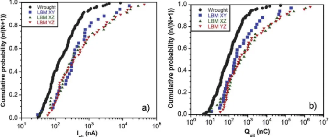
plotted. The only values extracted from those curves were the median values (Table 5), in order to illustrate the comments; however, one must be careful with the meaning given to these numerical values. The cu-mulative probability curves of Ipitand Qpitare shown inFig. 11for the
wrought and LBM samples. As showed by the plots, these curves had the same shape. A significant difference could be observed between
wrought and LBM samples, but a less marked difference could be also
noticed between LBM XY sample and LBM (X,Y)Z samples. Results clearly showed that the metastable pits formed on the LBM XZ and YZ samples corresponded to both higher current intensity and higher amount of charge than metastable pits grown on LBM XY sample, and even more than those formed on the wrought MSS. This could be seen also by considering the median values of Ipitand Qpit, even though there
was not a significant difference in the Ipitvalues obtained for the 3 LBM
samples. Moreover, another parameter was calculated for each sample, i.e. Qtotal, which corresponded to the sum of the Qpitvalues measured
during the 5 tests: Qtotalwas found to be equal to 132, 307, 1650 and
3414μC for the wrought, LBM XY, LBM XZ and LBM YZ samples,
re-spectively. Those values were in good agreement with the Ipitand Qpit
values, with a total amount of charge corresponding to metastable pits
significantly lower for the wrought MSS compared to LBM MSSs,
de-spite a higher number of metastable pits formed on the wrought MSS; furthermore, the difference in metastable pitting behaviour between the
LBM XY sample and the LBM (X,Y)Z samples was again clearly visible. Fig. 12 shows the cumulative probability curves plotted for Tg
(Fig. 12a), Tr(Fig. 12b) and the growth rate (Ipit/ Tg) (Fig. 12c), for all
MSSs. The curves had a similar shape as those plotted for Ipitand Qpit.
Furthermore, the results showed that the metastable pits formed on the wrought MSS had a shorter life time than those formed on LBM MSSs. Moreover, as already observed with Ipitand Qpitparameters, the LBM
XY MSS clearly had a different reactivity than the other LBM samples,
with a shorter life time of the metastable pits formed on the surface of the LBM XY sample compared to LBM XZ and YZ samples. This was visible also by considering the median values, in particular those of Tg.
The specific reactivity of the LBM XY sample was also evidenced on the
cumulative probability curve plotted for the growth rate of the me-tastable pits (Fig. 12c). Some metastable pits formed on the LBM XY sample reached a maximal growth rate value three times higher than metastable pits formed on the wrought and LBM (X,Y)Z samples, in agreement with the median values of the growth rate (Table 5).
Therefore, the cumulative probability curves plotted for all para-meters previously defined as characteristic of the metastable pits
showed significant differences in the metastable pitting behaviour
be-tween the LBM MSS and the wrought one, but also bebe-tween LBM XY sample and the LBM (X,Y)Z samples. It could be concluded from this statistical analysis that the wrought MSS was characterised by the nu-cleation of numerous pits which could not reach a stable growth and quickly repassivated, before reaching a high current value, which cor-responded to a low amount of dissolved steel. On the contrary, for LBM MSS, the number of metastable pits formed was lower, but the pits
Fig. 10.Current transients corresponding to metastable pits for a) the wrought MSS, and b) LBM XY MSS. Table 5
Median values of the parameters representative of the metastable pits. Values are extracted from the current versus time curves.
Ipit(nA) Qpit(nC) Tg(s) Tr(s) Ipit/ Tg(nA/s)
wrought 133 90 1.1 0.2 148 LBM XY 329 211 1.6 0.4 214 LBM XZ 310 415 3.2 0.4 160 LBM YZ 344 334 2.6 0.4 185
could propagate for a longer duration time and reached higher maximal current values, which corresponded to a stronger dissolution of the MSS. It could be therefore concluded, in a first approach, that the
metastable pits formed for LBM samples were more“stable”than those
formed for the wrought MSS. Moreover, results also showed that the LBM XY sample had a specific behaviour compared to the LBM XZ and
YZ samples. Indeed, considering the Ipit, Qpit, Qtotal, Tgand Trvalues,
the LBM XY sample tended to show a metastable pitting behaviour closer to that of the wrought alloy than the LBM XZ and YZ samples; however, it was characterised by higher growth rate values compared to both the wrought MSS and the LBM XZ and YZ samples, even though such values were characteristic of only a few metastable pits, that
behave differently than the other pits (Fig. 12c).
Those results could indicate that the wrought MSS would be more resistant to metastable pitting than the LBM MSS, for the same heat treatment (H900), considering in particular the life time of the me-tastable pits, the Ipitand Qpitvalues. However, the description of the
results above showed the complexity of the metastable pitting analysis. One could try to explain this result by referring to the pores present in the LBM samples. Indeed, if the pores were preferential sites for the formation of metastable pits, those pits could grow leading to high current due to the quite confined medium trapped inside the pores. This
would be consistent with the higher Ipit, Qpit, and Tgvalues measured
for the LBM samples as compared to the wrought MSS. However, con-sidering that the number of stable pits formed near a pore was very low, it was assumed that the passivefilm would reform inside the pores.
Then, to explain that the density of stable pits was similar for LBM and wrought MSSs, while the density of metastable pits was lower for LBM samples compared to the wrought sample, the only robust conclusion the results could support was that the passivefilms formed on the
dif-ferent samples might be slightly different and therefore might present
differences in terms of stability, at least during thefirst stages of
im-mersion of the samples in the electrolyte. This would be consistent with the ipassvalues (Fig. 5c,Table 3), showing that the amount of charge
used for the growth of the passivefilm was lower for the LBM MSSs
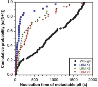
compared to the wrought MSS. This would be also consistent with the conclusions that could be drawn by considering the cumulative prob-ability curves plotted for a last parameter, i.e. the nucleation time of the metastable pits (Fig. 13). These curves clearly showed that, for the LBM XY sample, 80 % of the metastable pits were formed in thefirst 200 s,
whereas, for the wrought MSS, the metastable pits formed during the whole potentiostatic tests. The LBM XZ and YZ samples showed an in-termediate behaviour. These results suggested a stronger evolution of the passivefilms formed on the LBM samples during the immersion in
the NaCl solution, compared to the wrought MSS. At the beginning of the immersion, metastable pits could form on the LBM samples, char-acterised by a high current and long life time, but, after a duration time of immersion, the resistance of the passivefilms formed on the LBM
samples would be better leading to a stop in the initiation of metastable pits. This would be in agreement with the OCP measurements per-formed (Fig. 5a), that showed that the LBM samples did not reach steady state conditions even after 24 h of immersion contrary to the wrought MSS. This would be also consistent with the shift of Epittoward
more positive potentials. Therefore, as said above, the most relevant hypothesis to explain the differences in pitting behaviour of the
Fig. 12.Cumulative probability distribution of metastable pit a) growth time Tg, b) repassivation time Trand c) growth rate Ipit/ Tg.
Fig. 13.Cumulative probability distribution of the nucleation time of me-tastable pits.
wrought and LBM samples was the existence of differences in the
composition and / or structure of the passivefilms. Such results could
be related directly to the small differences in chemical composition
between the wrought MSS and the LBM MSSs, in particular to the Cr and Ni content, but also to the differences in microstructure previously
observed, e.g. austenite / martensite ratio, the lath size and the size and density of Cu-rich precipitates. It is clear that the differences in
mi-crostructure are also themselves related, at least for a certain part, to the differences in chemical composition between the two steels. In the
same way, the specific behaviour of the LBM XY sample could be
in-terpreted considering in particular the high amount of austenite mea-sured for this sample. Finally, as said previously, the presence of pores inside the LBM samples could not be neglected. Previous results showed that their influence on the stable pitting behaviour of the LBM samples
studied here was assumed to be negligible due their very low amount. However, this did not mean that pores could not influence the passive films properties. Indeed, Laleh et al. observed an unexpected low
ero-sion-corrosion resistance for a SLM 316 L SS, as compared to the com-mercial counterpart; for the authors, even though the pores did not influence the pitting corrosion behaviour, they could modify the
re-passivation ability of the SS due to chemistry changes inside the pores. Such an analysis could explain the fact that, in the present study, the LBM samples showed more positive Epitvalues (Fig. 5), but seemed to
be less resistant to metastable pitting (Fig. 9andTable 5), as compared to the wrought MSS. Moreover, the influence of Si-rich oxides inside the
pores on the repassivation ability at these sites could be evoked [27], but, at the present time, no experimental data could be given to assess this hypothesis, apart from the fact that TEM observations of Si-rich oxide inclusions (Fig. 4) gave meaning to this hypothesis. Furthermore, Laleh et al. also proposed that residual stresses could contribute to the weak repassivation ability of the SLM 316 L SS [42]. Such a hypothesis was also relevant concerning the LBM samples studied here. Therefore, the results showed that there were several microstructural parameters that could contribute to explain the differences in pitting behaviour
observed between all the samples, considering both metastable and stable pitting. Whereas the influence of NbCs on the pitting corrosion
behaviour seemed to be clear, much more detailed study is required to evaluate the influence of other microstructural parameters, e.g. the
austenite content. Further work is in progress with corrosion tests performed on LBM samples with different heat treatment states related
to different microstructures in order to identify the individual role of
each metallurgical parameter.
4. Conclusions
The pitting corrosion behaviour of a 17-4PH MSS manufactured by LBM process was investigated in NaCl solution and compared to that of a wrought MSS. The main conclusions are the following:
1 Solution annealing and H900 ageing heat treatments led to a homogeneous microstructure with recrystallised grains for both the wrought and LBM MSSs. However, the LBM MSS had afiner
mi-crostructure, with finer martensite laths,finer NbCs precipitates,
contained more austenite and more Cu-rich precipitates than the wrought MSS.
2 Polarisation curves plotted in 0.5 M NaCl suggested that the pitting corrosion behaviour of the 17-4PH MSS was improved by the LBM process at the same heat treatment (H900), considering lower ipass
and more positive Epitvalues for the LBM samples compared to the
wrought MSS. Results showed a detrimental influence of NbCs on pit
initiation; the smaller size of NbCs in the LBM samples could con-tribute to explain the shift of Epittowards more positive values as
compared to the wrought sample. Furthermore, OM observations clearly showed that lack-of-fusion pores were preferential pit in-itiation sites; however, due to their very low amount in the LBM samples studied, they did not influence their pitting corrosion
resistance. The influence of small gas pores was assumed to be
negligible.
3 Metastable pits generated on the LBM 17-4PH MSS were very few, characterised by a long life time and a high amount of charge, whereas the wrought MSS presented more metastable pits with short life time and a low amount of charge, which demonstrated sig-nificant differences in the metastable pitting behaviour between the
LBM and wrought MSSs. Furthermore, for the LBM MSS, a slight difference between XY plane and (X,Y)Z planes reactivity could be
also observed. The results were explained by referring to differences
in the passivefilm properties between the different samples, in
re-lation to the differences in microstructure observed. In particular,
even though small gas pores seemed to have no influence on stable
pit initiation, they were assumed to modify the repassivation ability of the LBM samples.
The results were of main interest for the use of the LBM 17-4PH MSS. Indeed, it seemed that, referring to the stable pitting behaviour of the MSS, the LBM process did not induce any degradation of the properties, and even more it led to a shift of Epittowards more positive
values. However, considering the susceptibility of the alloy toward stress corrosion cracking, the results obtained relative to the metastable pitting raised several questions, in particular concerning the influence
of the LBM process on the susceptibility to crack initiation.
5. Data availability
The raw/processed data required to reproduce thesefindings cannot
be shared at this time as the data also forms part of an ongoing study.
CRediT authorship contribution statement
Adrien Barroux: Investigation, Formal analysis, Validation,
Visualization, Methodology, Data curation, Writing - original draft, Writing - review & editing.Nadège Ducommun:Funding acquisition, Resources, Project administration, Supervision, Writing - review & editing.Eric Nivet:Funding acquisition, Resources, Project
adminis-tration, Supervision, Writing - review & editing. Lydia Laffont:
Methodology, Supervision, Validation, Conceptualization, Data cura-tion, Writing - original draft, Writing - review & editing.Christine
Blanc: Funding acquisition, Methodology, Project administration,
Supervision, Validation, Conceptualization, Data curation, Writing -original draft, Writing - review & editing.
Declaration of Competing Interest
The authors declare that they have no known competingfinancial
interests or personal relationships that could have appeared to infl
u-ence the work reported in this paper.
Acknowledgement
The authors thank the ANRT for their financial support (Adrien
Barroux’s PhD thesis).
Appendix A. Supplementary data
Supplementary material related to this article can be found, in the online version, at doi:https://doi.org/10.1016/j.corsci.2020.108594.
References
[1] R. Bhambroo, S. Roychowdhury, V. Kain, V.S. Raja, Effect of reverted austenite on mechanical properties of precipitation hardenable 17-4 stainlesssteel, Mater. Sci. Eng. A 568 (2013) 127–133,https://doi.org/10.1016/j.msea.2013.01.011.
Mater. Chem. Phys. 74 (2002) 134–142,https://doi.org/10.1016/S0254-0584(01) 00460-6.
[3] G. Yeli, M.A. Auger, K. Wilford, G.D.W. Smith, P.A.J. Bagot, M.P. Moody, Sequential nucleation of phases in a 17-4PH steel: microstructural characterisation and me-chanical properties, Acta Mater. 125 (2017) 38–49,https://doi.org/10.1016/j. actamat.2016.11.052.
[4] L. Couturier, F. De Geuser, M. Descoins, A. Deschamps, Evolution of the micro-structure of a 15-5PH martensitic stainless steel during precipitation hardening heat treatment, Mater. Des. 107 (2016) 416–425,https://doi.org/10.1016/j.matdes. 2016.06.068.
[5] H.R. Habibi Bajguirani, C. Servant, G. Cizeron, TEM investigation of precipitation phenomena occurring in PH 15-5 alloy, Acta Metall. Mater. 41 (1993) 1613–1623, https://doi.org/10.1016/0956-7151(93)90270-3.
[6] H.R. Habibi Bajguirani, The effect of ageing upon the microstructure and
me-chanical properties of type 15-5 PH stainless steel, Mater. Sci. Eng. A 338 (2002) 142–159,https://doi.org/10.1016/S0921-5093(02)00062-X.
[7] R. Kapoor, I.S. Batra, On theα′toγtransformation in maraging (grade 350), PH
13-8 Mo and 17-4 PH steels, Mater. Sci. Eng. A 371 (2004) 324–334,https://doi.org/ 10.1016/j.msea.2003.12.023.
[8] A. Abbasi Aghuy, M. Zakeri, M.H. Moayed, M. Mazinani, Effect of grain size on
pitting corrosion of 304L austenitic stainless steel, Corros. Sci. 94 (2015) 368–376, https://doi.org/10.1016/j.corsci.2015.02.024.
[9] J. Wang, H. Zou, C. Li, S. Qiu, B. Shen, The effect of microstructural evolution on
hardening behavior of type 17-4PH stainless steel in long-term aging at 350 °C, Mater. Charact. 57 (2006) 274–280,https://doi.org/10.1016/j.matchar.2006.02. 004.
[10] H. Mirzadeh, A. Najafizadeh, Aging kinetics of 17-4 PH stainless steel, Mater. Chem. Phys. 116 (2009) 119–124,https://doi.org/10.1016/j.matchemphys.2009.02.049.
[11] U.K. Viswanathan, S. Banerjee, R. Krishnan, Effects of aging on the microstructure of 17-4 PH stainless steel, Mater. Sci. Eng. A 104 (1988) 181–189,https://doi.org/ 10.1016/0025-5416(88)90420-X.
[12] T. DebRoy, H.L. Wei, J.S. Zuback, T. Mukherjee, J.W. Elmer, J.O. Milewski, A.M. Beese, A. Wilson-Heid, A. De, W. Zhang, Additive manufacturing of metallic components–process, structure and properties, Prog. Mater. Sci. 92 (2018)
112–224,https://doi.org/10.1016/j.pmatsci.2017.10.001.
[13] H. Fayazfar, M. Salarian, A. Rogalsky, D. Sarker, P. Russo, V. Paserin, E. Toyserkani, A critical review of powder-based additive manufacturing of ferrous alloys: process parameters, microstructure and mechanical properties, Mater. Des. 144 (2018) 98–128,https://doi.org/10.1016/j.matdes.2018.02.018.
[14] F. Huber, C. Bischof, O. Hentschel, J. Heberle, J. Zettl, K. Yu, Nagulin, M. Schmidt, Laser beam melting and heat-treatment of 1.2343 (AISI H11) tool steel–
micro-structure and mechanical properties, Mater. Sci. Eng. A 742 (2019) 109–115, https://doi.org/10.1016/j.msea.2018.11.001.
[15] A. Kudzal, B. McWilliams, C. Hofmeister, F. Kellogg, J. Yu, J. Taggart-Scarff, J. Liang, Effect of scan pattern on the microstructure and mechanical properties of
powder bed fusion additive manufactured 17-4 stainless steel, Mater. Des. 133 (2017) 205–215,https://doi.org/10.1016/j.matdes.2017.07.047.
[16] H. Gu, H. Gong, D. Pal, K. Rafi, T. Starr, B. Stucker, Influences of energy density on
porosity and microstructure of selective laser melted 17-4PH stainless steel, 2013 Solid Freeform Fabrication Symposium (2013) 474.
[17] L.E. Murr, E. Martinez, J. Hernandez, S. Collins, K.N. Amato, S.M. Gaytan, P.W. Shindo, Microstructures and properties of 17-4 PH stainless steel fabricated by selective laser melting, J. Mater. Res. Technol. 1 (2012) 167–177,https://doi.org/ 10.1016/S2238-7854(12)70029-7.
[18] S.D. Meredith, J.S. Zuback, J.S. Keist, T.A. Palmer, Impact of composition on the heat treatment response of additively manufactured 17–4 PH grade stainless steel,
Mater. Sci. Eng. A 738 (2018) 44–56,https://doi.org/10.1016/j.msea.2018.09.066.
[19] S. Cheruvathur, E.A. Lass, C.E. Campbell, Additive manufacturing of 17-4 PH stainless steel: post-processing heat treatment to achieve uniform reproducible microstructure, JOM 68 (2016) 930–942, https://doi.org/10.1007/s11837-015-1754-4.S.
[20] A. Yadollahi, N. Shamsaei, S.M. Thompson, A. Elwany, L. Bian, Mechanical and microstructural properties of selective laser melted 17-4 PH stainless steel, ASME 2015 International Mechanical Engineering Congress and Exposition, American Society of Mechanical Engineers, 2015, https://doi.org/10.1115/IMECE2015-52362.
[21] A. Yadollahi, N. Shamsaei, S.M. Thompson, A. Elwany, L. Bian, Effects of building orientation and heat treatment on fatigue behavior of selective laser melted 17-4 PH stainless steel, Int. J. Fatigue 94 (Part 2) (2017) 218–235,https://doi.org/10.1016/ j.ijfatigue.2016.03.014.
[22] T. Lebrun, K. Tanigaki, K. Horikawa, H. Kobayashi, Strain rate sensitivity and mechanical anisotropy of selective laser melted 17-4 PH stainless steel, Mech. Eng. J. 1 (2014),https://doi.org/10.1299/mej.2014smm0049.
[23] T. LeBrun, T. Nakamoto, K. Horikawa, H. Kobayashi, Effect of retained austenite on
subsequent thermal processing and resultant mechanical properties of selective laser melted 17–4 PH stainless steel, Mater. Des. 81 (2015) 44–53,https://doi.org/ 10.1016/j.matdes.2015.05.026.
[24] F. Hengsbach, P. Koppa, K. Duschik, M.J. Holzweissig, M. Burns, J. Nellesen, W. Tillmann, T. Tröster, K.-P. Hoyer, M. Schaper, Duplex stainless steel fabricated by selective laser melting - microstructural and mechanical properties, Mater. Des. 133 (2017) 136–142,https://doi.org/10.1016/j.matdes.2017.07.046.
[25] R. Rashid, S.H. Masood, D. Ruan, S. Palanisamy, R.A. Rahman Rashid, M. Brandt, Effect of scan strategy on density and metallurgical properties of 17-4PH parts printed by Selective Laser Melting (SLM), J. Mater. Process. Technol. 249 (2017) 502–511,https://doi.org/10.1016/j.jmatprotec.2017.06.023.
[26] Y. Sun, R.J. Hebert, M. Aindow, Non-metallic inclusions in 17-4PH stainless steel parts produced by selective laser melting, Mater. Des. 140 (2018) 153–162,https://
doi.org/10.1016/j.matdes.2017.11.063.
[27] X. Lou, P.L. Andresen, R.B. Rebak, Oxide inclusions in laser additive manufactured stainless steel and their effects on impact toughness and stress corrosion cracking
behavior, J. Nucl. Mater. 499 (2018) 182–190,https://doi.org/10.1016/j.jnucmat. 2017.11.036.
[28] D. Kong, X. Ni, C. Dong, L. Zhang, C. Man, J. Yao, K. Xiao, X. Li, Heat treatment effect on the microstructure and corrosion behavior of 316L stainless steel fabri-cated by selective laser melting for proton exchange membrane fuel cells, Electrochim. Acta 276 (2018) 293–303,https://doi.org/10.1016/j.electacta.2018. 04.188.
[29] S.-Y. Lu, K.-F. Yao, Y.-B. Chen, M.-H. Wang, N. Chen, X.-Y. Ge, Effect of quenching
and partitioning on the microstructure evolution and electrochemical properties of a martensitic stainless steel, Corros. Sci. 103 (2016) 95–104,https://doi.org/10. 1016/j.corsci.2015.11.010.
[30] S.S.M. Tavares, F.J. da Silva, C. Scandian, G.F. da Silva, H.F.G. de Abreu, Microstructure and intergranular corrosion resistance of UNS S17400 (17-4PH) stainless steel, Corros. Sci. 52 (2010) 3835–3839,https://doi.org/10.1016/j.corsci. 2010.07.016.
[31] H. Luo, Q. Yu, C. Dong, G. Sha, Z. Liu, J. Liang, L. Wang, G. Han, X. Li, Influence of the aging time on the microstructure and electrochemical behaviour of a 15-5PH ultra-high strength stainless steel, Corros. Sci. 139 (2018) 185–196,https://doi. org/10.1016/j.corsci.2018.04.032.
[32] V. Vignal, S. Ringeval, S. Thiébaut, K. Tabalaiev, C. Dessolin, O. Heintz, F. Herbst, R. Chassagnon, Influence of the microstructure on the corrosion behaviour of low-carbon martensitic stainless steel after tempering treatment, Corros. Sci. 85 (2014) 42–51,https://doi.org/10.1016/j.corsci.2014.03.036.
[33] P. Marcus, V. Maurice, H.-H. Strehblow, Localized corrosion (pitting): a model of passivity breakdown including the role of the oxide layer nanostructure, Corros. Sci. 50 (2008) 2698–2704,https://doi.org/10.1016/j.corsci.2008.06.047.
[34] D. Nakhaie, M.H. Moayed, Pitting corrosion of cold rolled solution treated 17-4 PH stainless steel, Corros. Sci. 80 (2014) 290–298,https://doi.org/10.1016/j.corsci. 2013.11.039.
[35] M. Ziętala, T. Durejko, M. Polański, I. Kunce, T. Płociński, W. Zieliński, M.Łazińska, W. Stępniowski, T. Czujko, K.J. Kurzydłowski, Z. Bojar, The microstructure,
me-chanical properties and corrosion resistance of 316L stainless steel fabricated using laser engineered net shaping, Mater. Sci. Eng. A 677 (2016) 1–10,https://doi.org/ 10.1016/j.msea.2016.09.028.
[36] X. Chen, J. Li, X. Cheng, H. Wang, Z. Huang, Effect of heat treatment on micro-structure, mechanical and corrosion properties of austenitic stainless steel 316L using arc additive manufacturing, Mater. Sci. Eng. A 715 (2018) 307–314,https:// doi.org/10.1016/j.msea.2017.10.002.
[37] W.K. Chan, C.T. Kwok, K.H. Lo, Effect of laser surface melting and subsequent re-aging on microstructure and corrosion behavior of aged S32950 duplex stainless steel, Mater. Chem. Phys. 207 (2018) 451–464,https://doi.org/10.1016/j. matchemphys.2018.01.007.
[38] M.J.K. Lodhi, K.M. Deen, W. Haider, Corrosion behavior of additively manufactured 316L stainless steel in acidic media, Materialia 2 (2018) 111–121,https://doi.org/ 10.1016/j.mtla.2018.06.015.
[39] W.S.W. Harun, R.I.M. Asri, F.R.M. Romlay, S. Sharif, N.H.M. Jan, F. Tsumori, Surface characterisation and corrosion behaviour of oxide layer for SLMed-316L stainless steel, J. Alloys. Compd. 748 (2018) 1044–1052,https://doi.org/10.1016/ j.jallcom.2018.03.233.
[40] Q. Chao, V. Cruz, S. Thomas, N. Birbilis, P. Collins, A. Taylor, P.D. Hodgson, D. Fabijanic, On the enhanced corrosion resistance of a selective laser melted austenitic stainless steel, Scr. Mater. 141 (2017) 94–98,https://doi.org/10.1016/j. scriptamat.2017.07.037.
[41] M.J. Tobar, J.M. Amado, J. Montero, A. Yáñez, A study on the effects of the use of
gas or water atomized AISI 316L steel powder on the corrosion resistance of laser deposited material, Phys. Procedia 83 (2016) 606–612,https://doi.org/10.1016/j. phpro.2016.08.063.
[42] M. Laleh, A.E. Hughes, W. Xu, I. Gibson, M.Y. Tan, Unexpected erosion-corrosion behaviour of 316L stainless steel produced by selective laser melting, Corros. Sci. 155 (2019) 67–74,https://doi.org/10.1016/j.corsci.2019.04.028.
[43] R.N. Clark, J. Searle, T.L. Martin, W.S. Walters, G. Williams, The role of niobium carbides in the localised corrosion initiation of 20Cr-25Ni-Nb advanced gas-cooled reactor fuel cladding, Corros. Sci. 165 (2020) 108365, ,https://doi.org/10.1016/j. corsci.2019.108365.
[44] M.A. Melia, H.-D.A. Nguyen, J.M. Rodelas, E.J. Schindelholz, Corrosion properties of 304L stainless steel made by directed energy deposition additive manufacturing, Corros. Sci. 152 (2019) 20–30,https://doi.org/10.1016/j.corsci.2019.02.029.
[45] M. Laleh, A.E. Hughes, S. Yang, J. Li, W. Xu, I. Gibson, M.Y. Tan, Two and three-dimensional characterisation of localised corrosion affected by lack-of-fusion pores in 316L stainless steel produced by selective laser melting, Corros. Sci. 165 (2020) 108394, ,https://doi.org/10.1016/j.corsci.2019.108394.
[46] M. Laleh, A.E. Hughes, W. Xu, P. Cizek, M.Y. Tan, Unanticipated drastic decline in pitting corrosion resistance of additively manufactured 316L stainless steel after high-temperature post-processing, Corros. Sci. 165 (2020) 108412, ,https://doi. org/10.1016/j.corsci.2019.108412.
[47] P.C. Pistorius, G.T. Burstein, Growth of corrosion pits on stainless steel in chloride solution containing dilute sulphate, Corros. Sci. 33 (1992) 1885–1897,https://doi. org/10.1016/0010-938X(92)90191-5.
[48] G.T. Burstein, P.C. Pistorius, S.P. Mattin, The nucleation and growth of corrosion pits on stainless steel, Corros. Sci. 35 (1993) 57–62, https://doi.org/10.1016/0010-938X(93)90133-2.
[49] S. Pahlavan, S. Moazen, I. Taji, K. Saffar, M. Hamrah, M.H. Moayed, S. Mollazadeh
Beidokhti, Pitting corrosion of martensitic stainless steel in halide bearing solutions, Corros. Sci. 112 (2016) 233–240,https://doi.org/10.1016/j.corsci.2016.07.008.