Real-Time I/O System for
Many-core Embedded
Systems
Zhe Jiang
Doctor of Philosophy
University of York
Computer Science
August 2018
Abstract
In modern real-time embedded systems, time predictability is vital. This extends to I/O operations which require predictability, timing-accuracy, en-hanced performance, scalability, parallel access and isolation. Currently, exist-ing approaches cannot achieve all these requirements at the same time. In this thesis, we propose a framework of hardware-implemented real-time I/O virtu-alization system to meet all these requirements simultaneously — BlueIO.
BlueIO integrates the important functionalities of I/O virtualization and low layer I/O drivers (achieved via Virtualized Complicated Device Con-troller (VCDC)), as well as a clock cycle level timing-accurate I/O controller (i.e. GPIO Command Processor (GPIOCP)). BlueIO provides this func-tionality in the hardware layer, supporting abstract virtualized access to I/O devices from the software domain. The hardware implementation includes I/O virtualization and I/O drivers provide isolation and parallel (concurrent) access to I/O operations and improves I/O performance. Furthermore, the approach includes GPIOCP to guarantee that I/O operations will occur at a specific clock cycle (i.e. be timing-accurate and predictable).
This thesis proposes the design and implementation of BlueIO, together with its components — GPIOCP and VCDC. It is demonstrated how a BlueIO-based system can be exploited to meet real-time requirements with significant improvements in I/O performance and low running cost on different OSs. The thesis presents a hardware consumption analysis of BlueIO, in order to show that it linearly scales with the number of CPUs and I/O devices.
Finally, the thesis proposes a scalable real-time hardware hypervisor termed BlueVisor, which is built upon proposed modules. BlueVisor enables pre-dictable virtualization on CPU, memory, and I/O; together with fast interrupt handling and inter-virtual machine communication. BlueVisor shows that the approaches towards I/O proposed in this thesis can be applied and expanded to different architectures, whilst maintaining required properties.
Contents
Abstract ii
Contents iii
List of Figures viii
List of Tables xi
Acknowledgement xiii
Declaration xiv
1 Introduction 1
1.1 Input and Output Systems (I/O Systems) . . . 2
1.2 Performance Features . . . 2 1.3 Real-time Features . . . 3 1.4 Protection Features . . . 5 1.4.1 Virtualization Technology . . . 5 1.5 Hypothesis . . . 8 1.6 Success Criteria . . . 9 1.7 Structure . . . 10 2 Literature Review 12 2.1 Real-time System . . . 12 2.1.1 Classifications . . . 12
2.1.2 Deriving Worst Case Execution Time (WCET) . . . 13
2.2 Input and Output Systems (I/O Systems) . . . 16
2.2.1 I/O Devices . . . 17
2.2.2 I/O Controllers . . . 18
2.2.4 Conflict to Performance and Real-time Features . . . . 22
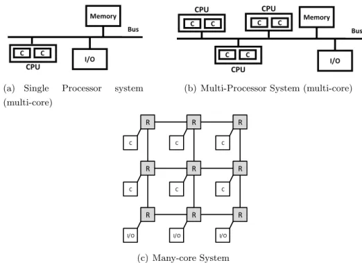
2.3 The Move to Multi-core and Many-core . . . 24
2.3.1 Bus-based Multi-core System . . . 25
2.3.2 NoC-based Many-core System . . . 26
2.3.3 I/O Systems in Multi-core and Many-core Systems . . . 27
2.3.4 Real-time Many-core Architectures . . . 29
2.4 Virtualization Technology . . . 30
2.4.1 Notions of Virtualization . . . 30
2.4.2 Classification of Virtualization . . . 32
2.4.3 Conflict in Performance and Real-time Features . . . 34
2.4.4 Real-time Virtualization . . . 36
2.4.5 I/O Virtualization . . . 38
2.4.6 Hardware-assisted I/O virtualization . . . 42
2.5 Programmable Timely I/O Controllers . . . 43
2.5.1 Programmable Real-time Unit (PRU) . . . 44
2.5.2 Time Processor Unit (TPU) . . . 45
2.5.3 Programmable Real-time Unit (PRU) . . . 45
2.6 Implementations Fabrics for Embedded Systems . . . 46
2.6.1 Application-Specific Integrated Circuits (ASICs) . . . . 47
2.6.2 Field-Programmable Gate Arrays (FPGAs) . . . 47
2.6.3 ASICs vs FPGAs . . . 49
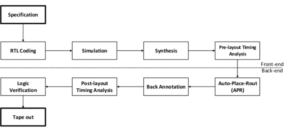
2.6.4 Design Flows . . . 50
2.6.5 Generic Fabric Designs . . . 52
2.7 Summary and Problem Statements . . . 53
3 Real-time I/O System 57 3.1 Baseline Systems . . . 58
3.2 Performance Features . . . 59
3.2.1 I/O Performance . . . 59
3.2.2 Timing Scalability Model . . . 60
3.3 Real-time Features . . . 62 3.3.1 Predictability . . . 62 3.3.2 Timing-accuracy Model . . . 63 3.4 Protection Features . . . 65 3.4.1 Parallel Access . . . 65 3.4.2 Isolation . . . 65 3.5 Summary . . . 65
4 VCDC: The Virtualized Complicated Device Controller 67
4.1 Overview . . . 68
4.1.1 Background . . . 68
4.1.2 Design Idea . . . 69
4.2 Virtualized Complicated Device Controller (VCDC) . . . 70
4.2.1 Virtualization in the VCDC Systems . . . 71
4.2.2 Guest Virtual Machine and Guest OS . . . 71
4.2.3 Overall Architecture . . . 73
4.2.4 Detailed Architecture . . . 74
4.3 Evaluation . . . 78
4.3.1 Performance features: Response Time of I/O Operations 80 4.3.2 Performance features: I/O Throughput . . . 82
4.3.3 Performance Feature: Scalability . . . 83
4.3.4 Hardware and Software Overhead . . . 88
4.3.5 On-chip Communication Overhead . . . 90
4.4 Summary . . . 91
5 GPIOCP: Timing-Accurate Real-time I/O Controller 93 5.1 Overview . . . 94
5.1.1 Context . . . 94
5.1.2 Approach . . . 94
5.2 GPIO Command Processor (GPIOCP) . . . 95
5.2.1 Hardware Manager . . . 97
5.2.2 Command Memory Controller . . . 98
5.2.3 Command Queue . . . 99
5.2.4 Synchronisation Processor . . . 101
5.3 GPIOCP Commands . . . 102
5.3.1 Example . . . 103
5.3.2 Invoking a GPIOCP Command . . . 104
5.4 Evaluation . . . 104
5.4.1 Real-time Performance . . . 105
5.4.2 Hardware Overhead . . . 106
5.4.3 Case Study . . . 107
6 BlueIO: The Scalable Real-Time Hardware I/O Virtualization
System 111
6.1 Overview . . . 112
6.1.1 General Architecture . . . 112
6.1.2 Context . . . 113
6.1.3 Virtual Machine (VM) and Guest OS . . . 114
6.2 BlueIO . . . 115
6.2.1 BlueGrass . . . 116
6.2.2 Virtualized Complicated Device Controller (VCDC) [72] 117 6.2.3 GPIO Command Processor (GPIOCP) [120] . . . 118
6.2.4 BlueTree [62] . . . 120
6.3 Hardware Consumption Analysis . . . 121
6.3.1 Implementing BlueIO in VLSI . . . 123
6.3.2 Hardware Consumption in RTL Level (FPGA) . . . 124
6.4 Evaluation . . . 126
6.4.1 Memory Footprint . . . 127
6.4.2 Real-time Features . . . 128
6.4.3 Performance Features — I/O Performance . . . 129
6.4.4 Performance Features — Timing Scalability . . . 132
6.4.5 On-chip Communication Overhead and Scalability . . . 135
6.5 Summary . . . 136
7 BlueVisor: A Scalable Real-Time Hardware Hypervisor for Many-core Embedded Systems 139 7.1 Overview . . . 140
7.1.1 General Architecture . . . 140
7.2 BlueVisor: Implementation . . . 141
7.2.1 CPU Virtualization and Guest VM . . . 141
7.2.2 Memory Virtualization . . . 143 7.2.3 I/O Virtualization . . . 145 7.2.4 Interrupt Management . . . 145 7.2.5 Inter-VM Communication . . . 146 7.3 Evaluation . . . 147 7.3.1 Memory Footprint . . . 148 7.3.2 Hardware Consumption . . . 149 7.3.3 Real-time Features . . . 150 7.3.4 I/O Performance . . . 151
7.3.5 Interrupt Handling . . . 153
7.4 Limitations of BlueVisor . . . 154
7.5 Summary . . . 154
8 Conclusion and Future Work 157 8.1 Major Contributions and Key Findings . . . 160
8.2 Future Work . . . 163
8.2.1 Supporting SMP OS . . . 163
8.2.2 Timing Analysis — Hard Real-time . . . 163
8.2.3 Supporting More I/O Drivers . . . 164
8.3 Closing Remarks . . . 164
Appendices 166 A Implementing a GPIOCP/VCDC/BlueIO/BlueVisor 167 A.1 Generic Number of Processors . . . 169
B Connecting GPIOCP/VCDC/BlueIO/BlueVisor to a Bluetile Many-core System 170 B.1 Building Bluetile system . . . 171
B.1.1 Compiling Bluespec System Verilog Files . . . 172
B.1.2 Encapsulating Verilog Files as IP cores . . . 172
B.1.3 Building the NoC . . . 172
B.1.4 Connecting Local Components . . . 173
B.1.5 Building a Bluetile System with Script . . . 174
B.2 Connecting GPIOCP/VCDC/BlueIO/BlueVisor to a Bluetile System . . . 174
C Running FreeRTOS/uCosII/Xilinx Kernel 175 C.1 Building BSP of FreeRTOS . . . 175
C.2 Adding the I/O Manager . . . 176
C.3 Invoking High Layer I/O Drivers . . . 176
List of Figures
1.1 Flow of I/O Request in Traditional Virtualization System . . . 6 2.1 Graphical view of the execution times of a task, along with the
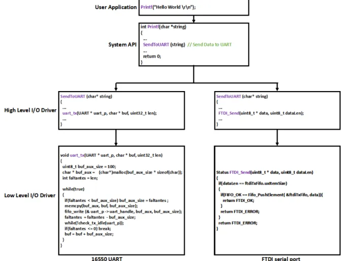
relevant bounds [114] . . . 15 2.2 Structure of I/O System in a Conventional Bus-based System . 16 2.3 A General-purposed I/O Controller [67] . . . 18 2.4 Two types of I/O Controllers . . . 19 2.5 Send “Hello World” from High Layer Application to the I/O
devices . . . 21 2.6 An Example of a Shared Bus . . . 25 2.7 An Example of Crossbar Interconnects (AXI Bus) [30]
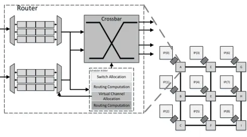
SI = Slave Interface; MI = Master Interface . . . 25 2.8 Examples of NoC and Router Architectures
A - G: Routers; IP: Intellectual Property core . . . 26 2.9 Structure of Multi-processor and Many-core Systems with I/O
devices. C - Core, R - Router/Arbiter . . . 27 2.10 Hosted-Virtualization . . . 33 2.11 Bare-metal virtualization . . . 34 2.12 Models to Achieve I/O Virtualization
(The grey parts are involved in Virtualization implementation) 39 2.13 Traditional System and a System with Solarflare NIC ASIC [15] 44 2.14 Comparison of Conventional and PRU-based Embedded Systems 45 2.15 Early FPGA Architecture [29] . . . 48 2.16 Simple Design Flow of ASICs . . . 51 2.17 Simple Design Flow of FPGAs . . . 52 3.1 Example of a Baseline System
4.1 FreeRTOS Kernel in a non-VCDC systems . . . 72
4.2 FreeRTOS Kernel in a VCDC system . . . 72
4.3 Overall architecture of a NoC with VCDC VM - Virtual Machine; R - Router / Arbiter . . . 73
4.4 Architecture of VCDC . . . 74
4.5 Architecture of Hardware Manager . . . 75
4.6 Architecture of Hardware Manager . . . 76
4.7 Architecture of I/O Low Layer Driver . . . 78
4.8 Experimental Platform R - Router / Arbiter; M - Microblaze; VM - Guest Virtual Machine; T - Timer . . . 79
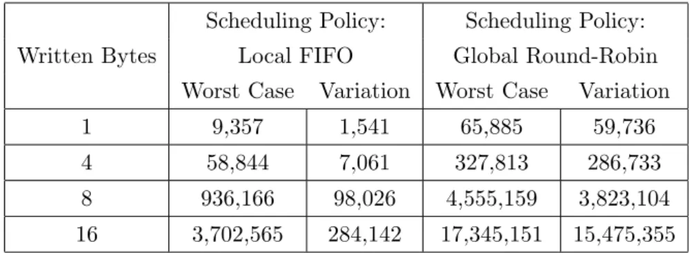
4.9 Performance feature: I/O Throughput FIFO — Local FIFO; RoundRobin — Global RoundRobin . . 83
4.10 Connection between VCDC and Ethernet System . . . 84
4.11 Virtualization Module of Ethernet I/O VMM . . . 85
5.1 GPIOCP Connected to a NoC (R - Router / Arbiter; T - Global Timer) . . . 96
5.2 Architecture of GPIOCP . . . 97
5.3 Architecture of Hardware Manager . . . 98
5.4 Architecture of Command Memory Controller . . . 99
5.5 Architecture of the GPIO Command Queue . . . 100
5.6 Architecture of Synchronization Processor . . . 101
5.7 Format of GPIO Subcommand . . . 103
5.8 Format of GPIO Command . . . 104
5.9 Experiment Platform R - Router/Arbiter M - Microblaze T - Global Timer . . . 105
6.1 Embedded Virtualization Architecture . . . 112
6.2 Platform Overview C - Core; R - Router / Arbiter; T - Global Timer . . . 113
6.3 Traditional and Modified FreeRTOS Kernels . . . 114
6.4 The Structure of the BlueIO . . . 115
6.5 The Structure of the BlueGrass . . . 116
6.6 Structure of VCDC . . . 118
6.7 Structure of GPIOCP . . . 119
6.9 Experimental Platform
(M - Microblaze; A - ARM Processor;
VM - Guest VM; R - Router / Arbiter) . . . 127
6.10 Experimental Setup for the Timing Accuracy of I/O Operations (T - Timer) . . . 129
6.11 I/O Throughput . . . 131
7.1 Embedded Virtualization Architecture . . . 141
7.2 Platform Overview M - Microblaze; A - ARM Processor; R - Router / Arbiter; T - Global Timer . . . 142
7.3 Traditional and Modified FreeRTOS Kernels . . . 143
7.4 Memory Configuration . . . 144
7.5 Two Types of Interrupt Handlers in BlueVisor System . . . 145
7.6 Inter-VM Communication . . . 146
7.7 Experimental Platform (M - Microblaze; A - ARM Processor; VM - Guest VM; R - Router / Arbiter) . . . 147
7.8 I/O Throughput . . . 153
8.1 Supporting SMP OS (M - Microblaze; R - Router / Arbiter) . . 163
A.1 Top Level Architecture of GPIOCP . . . 167
A.2 The Toplevel of the IP Core - GPIOCP . . . 168
B.1 Flow of Building Bluetile System . . . 171
B.2 Encapsulated Bluetile System IP Cores . . . 172
B.3 Size 2*3 BlutTile NoC . . . 173
B.4 Connecting an UART to the NoC . . . 173
B.5 Connecting the GPIOCP on the NoC . . . 174
C.1 BSP for different OSs . . . 175
C.2 Add the BSP . . . 176
C.3 I/O manager in FreeRTOS . . . 176
List of Tables
3.1 Baseline System Information . . . 59
3.2 Baseline System — I/O performance . . . 60
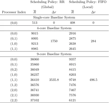
3.3 Baseline System — Timing Scalability . . . 61
3.4 Timing Scalability Model in Single-core, 4-core and 9-core Base-line Systems (unit: clock cycle) . . . 61
3.5 Baseline System — Predictability . . . 62
3.6 I/O Response Time in Baseline Systems (unit: Clock Cycles) . 63 3.7 Baseline System — Timing-accuracy . . . 63
3.8 The Errors in Timing-accuracy of I/O Operations in Baseline Systems (unit: ns) . . . 64
4.1 I/O response time in VCDC and non-VCDC systems (unit: clock cycle) . . . 81
4.2 Average Response Time of Loop Back 1KB Ethernet Packets in VCDC System (Global Scheduling Policy: Fixed Priority; Unit: us) . . . 87
4.3 Average Response Time of Loop Back 1KB Ethernet Packets in VCDC System (Global Scheduling Policy: Round Robin; Unit: us) . . . 88
4.4 Software Usage(object code) . . . 89
4.5 Hardware Usage (Without GPIOCP) . . . 89
4.6 On-chip Communication Overhead . . . 91
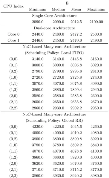
5.1 Errors in Timing-accuracy (E) in GPIOCP architecture . . . . 106
5.2 FPGA Hardware Usage L - Lookup Table, R - Register, B - BRAM . . . 107
5.3 Deadline Miss Rate in Two Architectures . . . 107
6.1 Hardware Consumption of Basic Modules (Gate Level) . . . 124 6.2 Hardware Consumption of BlueIO (Gate Level) . . . 125 6.3 Hardware Consumption of 2-CPU BlueIO with Different I/Os
on FPGA (RTL Level) . . . 126 6.4 Hardware Consumption of BlueIO (+GPIOCP) with Different
Number of CPUs on FPGA (RTL Level) . . . 126 6.5 BlueIO Memory Footprint (Bytes) . . . 128 6.6 I/O Response Time in Non-BlueIO Systems (unit: clock cycle)
(Summarized Version) . . . 130 6.7 I/O Response Time in BlueIO Systems (unit: clock cycle)
(Summarized Version) . . . 130 6.8 Average Response Time of Loop Back 1KB Ethernet Packets
in BlueIO System (Global Scheduling Policy: Fixed Priority; Unit: us) . . . 133 6.9 Average Response Time of Loop Back 1KB Ethernet Packets in
BlueIO System (Global Scheduling Policy: Round Robin; Unit: us) . . . 134 6.10 On-chip Communication Overhead . . . 136 7.1 BlueVisor Memory Footprint (Bytes)
(I/O: UART + VGA) . . . 149 7.2 Hardware Consumption of 2-CPU BlueVisor with Different I/Os
on FPGA (RTL Level) . . . 149 7.3 Hardware Consumption of BlueVisor (+GPIOCP) with
Differ-ent Number of CPUs on FPGA (RTL Level) . . . 150 7.4 Interrupt Handling (Unit: Clock Cycles) . . . 153
Acknowledgement
It would not be possible to complete my Ph.D. study and to finish this disser-tation without the help and support of the people around me.
Firstly, I would like to present my deepest appreciation to Prof. Neil Audsley for his persistent guidance, help and care for the past four years. Without him, my research work and this Ph.D. thesis would not be even possible. In addition, I would like to thank Prof. Andy Wellings for his assessments and comments during my whole Ph.D. study. He is always nice and patient to point out my weakness and encourage me to carry on my study. From him, I learned not only the right attitude not only on research but also on work and life. In addition, I would like to thank Dr. Ian Gray for his guidance and help duration my Ph.D. study.
I would also like to thank my parents for their unconditional support and continuously encouragement, which allows me to focus on my research and gives me the strength to overcome the difficulties and challenges from both my study and daily life.
The appreciation also goes to the members in the Real-time Systems group for their brilliant advice to my research and their encouragements. From my point of view, this the best research group in this world. I will be always proud of the group.
Finally, many thanks also go to my friends: Dr. Yunfeng Ma, Dr. Xinwei Fang, Dr. Haitao Mei, Dr. Shuai Zhao, Mr. Xiaotian Dai, Mr. Dizhong Zhu, Ms. Yanting Dai and Ms. Qianhan Xu –– for blowing my mind with the discussion of research questions and support me when I run to troubles.
Declaration
I declare that all work contained within this thesis is a result of my own investi-gations, except where explicit attribution has been given. The content of some of the chapters has already been published within the following publications:
• Zhe Jiang, and Neil C. Audsley. GPIOCP: Timing-accurate general pur-pose I/O controller for many-core real-time systems. Design, Automa-tion & Test in Europe Conference & ExhibiAutoma-tion (DATE), 2017. [120]
• Zhe Jiang, and Neil C. Audsley. VCDC: The Virtualized Complicated Device Controller. Euromicro Conference on Real-Time Systems (ECRTS), 2017. [72]
• Zhe Jiang, Neil C. Audsley and Pan Dong. BlueVisor: A scalable real-time hardware hypervisor for many-core embedded systems. Real-Time and Embedded Technology and Applications Symposium (RTAS), 2018. [73]
• Zhe Jiang, Neil C. Audsley and Pan Dong. BlueIO: A scalable real-time hardware I/O virtualization system for many-core embedded sys-tems. ACM Transactions on Embedded Computing Systems (TECS). (Accepted to be published) [121]
This work has not previously been presented for an award at this, or any other, University.
Chapter 1
Introduction
Recently, embedded systems have become widespread, e.g. in transportation systems, medical systems, mp3 players, telephone switches, etc. It is estimated that more than 99% of microprocessors are used for embedded systems [74,86]. By definition [115], an embedded system is:
a collection of programmable parts surrounded by Application-Specific Integrated Circuits (ASICs) and other standard compo-nents, that interact continuously with an environment through sensors and actuators.
In embedded systems, some component systems have bounded time con-straints. Often, these time constraints have to be guaranteed. Representative examples of such systems are flight controllers in aircraft, braking controllers in cars and train control systems. In these systems, an input stimuli must re-ceive a response before a given deadline, because any deadline miss may cause a catastrophic failure, even death. These systems are calledreal-time systems. The definition of a real-time system in [44] is:
a system that is required to react to stimuli from the environ-ment (including the passage of physical time) within time intervals dictated by the environment.
In architectures of embedded and computer systems, due to the recent breakdown of Dennard scaling [58], system designers have been not been able to improve system performance by increasing processor frequencies directly. Instead, in order to maintain expected year-on-year performance increases
(also known as Moore’s Law [99]), designers have turned to increase the num-ber of cores on one chip. Nowadays, an eight-core processor is commonplace, and the number of cores on one chip is continually increasing, e.g. Knight’s Landing is a commercial 72-core processor proposed by Intel [9], and Parallela has even proposed a 256-core processor [12]. Therefore, in order to efficiently achieve increased computational ability, the platforms of modern real-time sys-tems have been moved from single-core syssys-tems to multi-core and many-core systems.
1.1
Input and Output Systems (I/O Systems)
Not only in real-time systems, but also in all embedded and computer archi-tectures, an Input and Output system (I/O system) is vital, as:
• The I/O system extends the functionalities of the whole system [74];
• The I/O system provides interactive interfaces between the embedded and computer architectures and the outside world [115].
An I/O system is composed of I/O devices (peripherals), I/O controllers, and I/O drivers (specific details are described in Section 2.2).
1.2
Performance Features
In real-time systems (even single-core systems), I/O performance is a major system bottleneck [37, 72]. This mainly results from the significantly slower processing speed of normal I/O facilities compared to CPUs. This may result in the performance reduction of the whole system [72].
However, when it comes to real-time systems with more than one core, the bottleneck of I/O performance is magnified, mainly resulting from pro-cessor scheduling and contention over I/O resources. For example, in a tra-ditional bus-based multi-processor system (e.g. an AMBA High-performance Bus-based system [45]), if an I/O operation is requested by a user application, the system has to deal with scheduling between the cores in each processor, as well as I/O resource scheduling between different processors.
This leads to the first research question:
Research Question 1: How can I/O performance in real-time systems be enhanced by an increased number of cores? (com-pared to a traditional system)
In order to answer the question, an expected I/O system requires both enhanced I/O performance and good scalability, which are referred to as Per-formance Features in this thesis.
1.3
Real-time Features
As described in [44], satisfying timing constraints is a basic requirement of an I/O system in real-time systems:
• Predictability [104]: I/O operations have to be predictable in order to ensure a timely reaction when a critical situation occurs, e.g. the braking operations of a car are always required to be handled within a hard deadline [104].
• Timing-accuracy [120]: In real-time systems, I/O operations are often re-quired to be timely — occurring at a specific clock cycle.1 This feature is
vital for both I/O devices and the whole system. Specifically, on the I/O side, timing-accurate I/O operations achieve accurate control over I/O devices. For example, the accuracy of the motor controls in a 3D printer determines the accuracy of the final printed product [49, 56, 107]. When it comes to the system side, I/O operations are often requested repeat-edly and frequently with other system instructions. Frequent missing of clock cycles between I/O operations will damage the predictability of the whole system. Therefore, timing-accuracy is a vital feature for I/O devices, and even the whole system.
As defined in [106], predictability means:
1
In this thesis, all I/O devices share a single synchronization clock source with the whole system. For example, if the frequency of the system clock is 100 MHz, the granularity of a clock cycle is 10 ns.
It should be possible to show, demonstrate, or prove that require-ments are met subject to any assumptions made, e.g., concerning failures and workloads. In other words, predictability is always subject to the underlying assumptions being made.
As defined in [120], timing-accuracy is presented as:
If an operation occurs absolutely at the expected time, this oper-ation is totally timing-accurate.
However, achieving predictability of an I/O system is always challeng-ing [44], mainly resultchalleng-ing from the extremely uncertain execution time of I/O operations on various I/O devices, and the transmission latencies of I/O oper-ations from a user program to a targeted I/O device. Specifically, in standard computer and embedded architectures, even in a single-core system, latencies caused by device drivers and application process scheduling make predictable and timing-accurate I/O operations problematic, often leading to a dedicated CPU for the I/O application, or to that application being made the highest pri-ority. However, neither solution is scalable nor does it offer good predictability, timing-accuracy and resource use [120].
In multi-core and many-core systems, these issues are compounded. Whilst an application can invoke an I/O operation accurately via the interrupt of a high-resolution timer (e.g. the nanosecond timer provided by an RTOS [22, 23]), the transmission latencies from a CPU to an I/O controller can be sub-stantial and variable due to the communication bottlenecks and contention. For example, in a bus-based many-core system, the arbitration of the bus and the I/O controller may delay the I/O request. For a Network-on Chip (NoC) architecture, the arbitration of on-chip data flows across the communications mesh will also increase latencies. More details are introduced in Section 2.2 and Section 2.3
This leads to the second research question:
Research Question 2: Apart from performance features, how can the predictability and timing-accuracy of I/O operations in multi-core and many-core real-time systems be guaran-teed?
In this thesis, we classifypredictability and timing-accuracy as Real-time Features.
1.4
Protection Features
In practice, hard real-time systems are often associated with safety-critical systems [39, 44, 106], since any deadline miss may cause catastrophic failure of the whole system.
In safety-critical systems, in particular for I/O operations, isolation is an-other vital feature. Specifically, with the number of cores increased on one chip, I/O operations may be required to occur at the same time. For example, multiple motors in a 3D printer are required to be controlled simultaneously, in order to achieve efficient and precise controls on the nozzle [122]. However, it is common for different applications to try and access the same I/O device simultaneously, and even worse, a side channel may damage access attempts from the other cores.
In this situation, an I/O system should simultaneously enable parallel accesses and isolation of I/O operations. In this thesis, we term these two features Protection Features.
1.4.1 Virtualization Technology
Currently, virtualization technology is the most widely used technology [57,82] to achieve protection features (e.g. [82] [57] [66] and [109]). By definition [64], virtualization technology presents:
A framework or methodology of dividing the resources of a com-puter or an embedded system into multiple execution environ-ments, by applying one or more concepts or technologies such as
hardware and software partitioning, time-sharing, partial or com-plete machine simulation, emulation, quality of service, and many others.
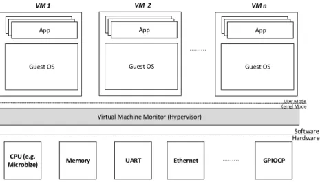
In a virtualization system, each independent execution environment (also known as a virtual machine (VM)) enables a guest operating systems (OS) to run logically isolated, which means I/O operations requested from different VMs can never affect each other [33, 102, 113]. At the same time, the I/O operations are also prevented from being affected by other VMs, even if the VMs break down [113].
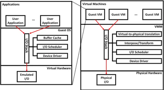
Moreover, other reasons for widespread use of virtualization in real-time systems are the superior benefits brought to the whole system, including increased resource use, reduced volume and cost of hardware and load bal-ance [33, 102]. User Application User Application … I/ O St ack Buffer Cache I/O Scheduler Device Driver Emulated I/O Applications Guest OS Virtual Hardware
Guest VM Guest VM … Guest VM
I/ O St ack Virtual-to-physical translation Interpose/Transform I/O Scheduler Physical I/O Virtual Machines VMM Device Driver Physical Hardware
Figure 1.1: Flow of I/O Request in Traditional Virtualization System
However, virtualization technology (I/O virtualization) involves compli-cated I/O access paths (i.e. indirection and interposition of privileged instruc-tions, see Figure 1.1) and complicated shared I/O resource management (i.e. scheduling and prioritization) [72, 102]. These two issues significantly conflict with the performance features (performance and scalability) and real-time fea-tures (predictability and timing-accuracy) [72,102]. Eliminating the issues and fitting virtualization technology to real-time systems is challenging.
Since virtualization technology relies on hardware support [33], today’s chip manufacturers have promoted different hardware assists in order to sim-plify the complicated I/O access paths and assist complicated shared I/O re-source management [33,94]. Intel’s Virtualization Technology for Directed I/O (VT-D) [68], which can provide direct I/O access from guest VMs, is an exam-ple of this. The IOMMU [39] is applied to commercial PCI-based systems to offload memory protection and address translation, in order to provide fast I/O access from guest VMs. These commonly used hardware-assisted I/O virtual-izations have successfully reduced the performance loss caused by complicated I/O paths, and complex shared I/O resource management, in traditional virtu-alized systems. However, they cannot improve I/O performance or guarantee real-time features (predictability and timing-accuracy) [33, 102, 120, 122]. For example, in [90], a hardware-based I/O virtualization approach using memory-mapped I/O, MMU and IOMMU is proposed, which achieves maximally only 73.10% of the normal DMA write data rate with no improvement on perfor-mance features or real-time features.
In order to improve real-time features, a number of real-time virtualizations have been proposed. For example, RT-Xen [116] integrates real-time schedul-ing theories with Xen [25] and instantiates a suite of fixed-priority servers (e.g. Deferrable Server), which is able to provide effective real-time scheduling to a guest Linux OS within a 1ms quantum. This gives good predictability, but no improvement on timing-accuracy. Similarly, Kiszka [76] proposed improve-ments in predictability regarding KVM, without any improvement in timing-accuracy. Generally, current approaches cannot satisfy the requirements of both performance and real-time. (Note that, more approaches are reviewed in Sections 2.4.4 and 2.4.5.) Therefore, current I/O virtualization cannot be directly applied to real-time systems. This leads to the third research question:
Research Question 3: How can performance features and real-time features for I/O systems be achieved when I/O vir-tualization is deployed (to achieve protection features)?
To sum up, in real-time arenas, the following features are required by an I/O system simultaneously:
– Enhanced I/O performance; – Scalability. • Real-time feature: – Predictability; – Timing-accuracy. • Protection feature: – Parallel accesses; – Isolation.
As mentioned in Section 1.1, the I/O system is one of the most vital parts of embedded and computer architectures. Therefore, research in the area of an I/O system have to be associated with a complete system, which leads to the fourth research question:
Research Question 4: How to integrate the ready-built I/O system to the complete system with the expected features inherited?
1.5
Hypothesis
Virtualization technology (i.e., I/O virtualization) has been shown to be a useful technique for achieving protection features to I/O operations (i.e. par-allel access and isolation). However, the deployment of I/O virtualization introduces complicated I/O access paths and complex shared I/O resource managements, which leads to decreased I/O throughput, worsen scalability, more complicated timing analysis, and decreased timing-accuracy compared to a non-virtualized system — significantly conflicting to the performance and real-time features. Therefore, current I/O virtualization cannot be directly applied to real-time systems.
The hypothesis of the thesis is that:
Effective real-time I/O and Virtualization can be achieved by moving Virtualization, I/O drivers and I/O operations into hardware.
The thesis will show that moving the virtualization layer and I/O drivers from software layer to hardware layer significantly increases I/O performance compared to traditional virtualized and non-virtualized sys-tems. Also, it will show that a programmable I/O controller contained in the virtualization system permits applications to instigate complex sequences of I/O operations at an exact time (the output values can be both static and dynamic), so achieving timing-accurate and predictable I/O operations with I/O virtualization.
Moreover, The design of the real-time I/O virtualization system is generic, which can be ported to different platforms with a scaled number of processors and I/O devices. Therefore, it can be directly applied to a real-time system, with the inherited performance features, real-time features and protection features.
1.6
Success Criteria
To facilitate the assessment of the work proposed in this thesis, a set of success criteria (SC) are given. In order to support the thesis hypothesis given in Section 1.5, the following need to be developed:
• SC-1: A virtualized complicated I/O controller that moves the function-alities of I/O virtualization and I/O drivers from the software layer to the hardware layer, which increases I/O throughput compared to both traditional virtualized and non-virtualized systems – performance fea-tures;
• SC-2: A timing-accurate I/O controller that can permit user applications to instigate complex sequences of I/O operations (with both static and dynamic output values) at an exact time, which achieves timing-accurate and more predictable I/O operations compared to traditional systems, which are real-time features (verified by experimentation).
• SC-3: A real-time I/O virtualization system built on SC-1 and SC-2 that can simultaneously support timing-accurate and predictable virtualized I/O operations with increased I/O throughput compared to traditional virtualized systems. The design of the I/O virtualization system can be scaled with a different number of processors and I/O devices;
• SC-4: A complete virtualization system built on the ready-built real-time I/O virtualization system (in SC-3), which inherits the expected real-time features (in SC-2) and performance features (in SC-1). The integration work verifies the design of the real-time I/O virtualization system (in SC-3) in an architecture agnostic way.
1.7
Structure
The thesis is structured as follows:
• Chapter 2 Reviews the background and related research of the thesis. Firstly, real-time systems, I/O systems and I/O systems in multi-core and many-core architectures are reviewed. Then, the literature related to achieving the expected features is reviewed, including virtualization technology, timely I/O controllers and implementation platforms. At the end of this chapter, the current problems which the thesis looks at solving are given.
• Chapter 3Firstly describes the system context of the research. It then introduces the six expected features of a real-time I/O system and their corresponding evaluation metrics, used in the following chapters.
• Chapter 4Proposes a hardware-implemented I/O virtualization system called Virtualized Complicated Device Controller (VCDC). It permits user applications to access and operate I/O devices directly from a guest VM, bypassing the guest OS, the VMM, and low layer I/O drivers. This achieves significant performance improvements (i.e. I/O perfor-mance and scalability), containing shorter I/O response time, greater I/O throughput and less on-chip communication overheads. This is ver-ified by evaluations in Section 4.3. This chapter provides the solution to research question 1.
• Chapter 5Proposes a resource efficient programmable I/O controller, termed the GPIO Command Processor (GPIOCP). It enables appli-cations to instigate complex sequences of I/O operations at an exactly specific clock cycle, thus achieving real-time features (i.e. predictabil-ity and timing-accuracy) which are verified by evaluation in Section 5.4. This chapter provides the solution to research question 2.
• Chapter 6 Proposes a real-time I/O virtualization system integrat-ing GPIOCP and VCDC, termed BlueIO. The evaluation results in Section 6.4 demonstrate that BlueIO inherits the benefits brought by GPIOCP and VCDC real-time features (i.e. timing-accuracy and pre-dictability) and performance features (i.e. enhanced I/O performance and scalability). Furthermore, due to the employment of I/O virtualiza-tion, significant protection features (i.e. parallel accesses and isolation) are also brought. This chapter demonstrates the solution to research question 3.
• Chapter 7Proposes a scalable real-time hardware hypervisor for multi-core and many-multi-core embedded architectures, termed BlueVisor, which is built on GPIOCP, VCDC and BlueIO. BlueVisor enables predictable virtualization on CPU, memory and I/O, as well as fast interrupt han-dler and inter-VM communication. The establishment of BlueVisor aims to show our methodologies can be applied and expanded to different ar-chitectures and platforms, with maintained features on real-time, per-formance and protection as evidenced by the evaluation results in Sec-tion 7.3
Chapter 2
Literature Review
This chapter introduces the background and literature related to this thesis, which is divided into four major parts:
Firstly, in Sections 2.1 to 2.3, the background material related to the thesis is reviewed, which includes real-time systems, I/O systems and I/O systems in multi-core and many-core architectures. Secondly, in Sections 2.4 and 2.5, the research on achieving performance features, real-time features and protection features for I/O systems is reviewed. Thirdly, in Section 2.6, an overview of implementation fabrics that are commonly used for embedded systems is given. Finally, Section 2.7 concludes with existing problems which are expected to be solved in the thesis.
2.1
Real-time System
The literature in real-time systems is broad. This section mainly presents a top-level view in order to place our work in context. More details are given when work is used later in the thesis. In this section, we review the basic classifications of real-time systems, and two classes of approaches commonly used to measure predictability in the systems.
2.1.1 Classifications
As introduced in [44], real-time systems are split into hard real-time systems, firm real-time systems, and soft real-time systems. Common definitions of the terms are [44]:
• Hard real-time system: Where it is absolutely imperative that the system reacts within its given time frame, else there may be disastrous consequences.
• Firm real-time system: Where the deadline may be missed occasion-ally, but there is no benefit from it being late.
• Soft real-time system: Where the deadline may be missed occasion-ally, or a service can occasionally be delivered late.
In firm real-time systems and soft real-time systems, there may be an upper limit on the times of tasks missing deadlines. In addition, some systems may have both soft real-time and hardware real-time requirements [44]. For example, a communication system may have a soft real-time deadline of 30ms for optimal signal processing; at the same time, a hard real-time deadline of 500ms also guarantees completion of basic communication.
In this situation, it is vital to determine the range of time in which the task executes in order to show that the task is able to meet the timing constraint. While determining the range of execution time, a commonly used technique in both academia and industry is predicting the Worst Case Execution Time (WCET) of the task.
2.1.2 Deriving Worst Case Execution Time (WCET)
As reviewed in [114], commonly used methodologies of achieving the WCET of tasks can be mainly classified into static analysis and measurement-based analysis.
2.1.2.1 Static Analysis
Static analysis is an offline methodology, attempting to analyse and calculate the WCET of tasks via modelling the target architecture [47]. As described in [54], static analysis has three steps:
• Flow analysis: Reconstructing all the possible paths through a process, via the source and the final output.
• Global low-level analysis: Computing the factors may affecting tasks on a specific machine via its global constructs (e.g. memory accessing).
• Local low-level analysis: Computing the same factors as above, but localised to a single task and code segment (pipeline).
In order to ensure the analysis is accurate, it is important to establish an extremely accurate model for the architecture, including processor, memory etc. In practice, if the architecture is simple, the model can be established eas-ily (e.g. Intel 8080 [2] uses a fixed number of clock cycles to execute different instructions). When it comes to complicated modern architectures, accurate modelling becomes almost impossible because of a mass of unpredictable fac-tors, e.g. cache, memory, etc. For example, in the modern Intel x86 [24] system architecture, different models of memory and cache may cause uncer-tain timing variances which are very difficult to predict. As described further in Section 2.3, the unpredictability of I/O also increases the difficulty of static analysis.
These factors result in issues with pessimism in static analysis. Because it is very hard to assert conditions on the state of the system, static analysis has to assert worst-case conditions. As an example, worst-case I/O access latencies are normally assumed and worst-case transmission latencies between processors and I/Os have to be assumed as well. Therefore, without a large number of assumptions, it will be very difficult to determine the WCET in practice.
2.1.2.2 Measurement-based Analysis
As it is different to rely on an extremely accurate model of the architecture (static analysis), measurement-based analysis adopts the behaviour of the sys-tem itself to measure the execution time [114].
As with static analysis, measurement-based analysis starts from recon-structing a flow graph of the program. Specifically, in the flow graph, a pro-gram is re-constructed into a number of basic blocks. In the measurement, the tool executes the program many times under a set of inputs and environment conditions. It then records the duration of each block, deriving a distribution of probabilities. After this, the execution time of each block can be combined into the flow graph. If the basic blocks are connected to a sequential func-tion, the execution times of each block are summed. If the basic blocks are connected to a parallel function (e.g. in a switch construct), the maximum execution time of all parallel blocks will be chosen. The combination of all these basic blocks forms an estimate of the WCET of the program.
asserted over, and hence may assume that cache blocks are missing when they will definitely reside in cache. Despite this pessimism, static analysis should always be able to find the worst-case path, assuming that the model of the processor is sound and is hence typically regarded as safer than measurement-based approaches.
Measurement-based Analysis
Rather on relying upon an accurate model of the processor, measurement-based analysis instead uses the behaviour of the processor itself to model the execution
times [34], after all, “the best model of the processor is the processor itself”. As
with static analysis, measurement based techniques begin by re-constructing a flow graph of the program, where each block in the graph typically corresponds to a single-entry single-exit block of instructions which are executed sequentially, typ-ically known as a basic block. The tool then executes the program a number of times under a set of inputs and environmental conditions, then times how long each of these blocks takes to execute to derive a distribution of probabilities for each block.
After this has taken place for each block, the execution times for each block can be combined according to the flow graph. If blocks are connected in a sequential fashion, then the execution times of each are summed, if they appear in parallel (e.g. in an if/then/else construct), then the maximum execution time of all of the parallel blocks is selected. The combination of all of these basic blocks then forms an estimate of the worst-case execution time of the entire task.The Worst-Case Execution-Time Problem • 36:3
Fig. 1. Basic notions concerning timing analysis of systems. The lower curve represents a subset
of measured executions. Its minimum and maximum are theminimalandmaximal observed
exe-cution times, respectively. The darker curve, an envelope of the former, represents the times of all
executions. Its minimum and maximum are thebest-andworst-case execution times, respectively,
abbreviated BCET and WCET.
exhaustively explore all possible executions and thereby determine the exact worst- and best-case execution times.
Today, in most parts of industry, the common method to estimate
execution-time bounds is to measure theend-to-endexecution time of the task for a subset
of the possible executions—test cases. This determines theminimal observed
andmaximal observed execution times. These will, in general, overestimate the
BCET and underestimate the WCET and so are not safe for hard real-time
systems. This method is often calleddynamic timing analysis.
Newer measurement-based approaches make more detailed measurements
of the execution time of differentparts of the task and combine them to give
better estimates of the BCET and WCET for the whole task. Still, these methods are rarely guaranteed to give bounds on the execution time.
Bounds on the execution time of a task can be computed only by methods that consider all possible execution times, that is, all possible executions of the task. These methods use abstraction of the task to make timing analysis of the task feasible. Abstraction loses information, so the computed WCET bound usually overestimates the exact WCET and vice versa for the BCET. The WCET bound
represents the worst-case guarantee the method or tool can give. How much
is lost depends both on the methods used for timing analysis and on overall system properties, such as the hardware architecture and characteristics of the
software. These system properties can be subsumed under the notion oftiming
predictability.
The two main criteria for evaluating a method or tool for timing analysis
are thussafety—does it produce bounds or estimates?— andprecision—are the
bounds or estimates close to the exact values?
Performance prediction is also required for application domains that do not have hard real-time characteristics. There, systems may have deadlines, but are not required to absolutely observe them. Different methods may be applied and different criteria may be used to measure the quality of methods and tools. ACM Transactions on Embedded Computing Systems, Vol. 7, No. 3, Article 36, Publication date: April 2008.
Figure 2.1:Graphical view of the execuiton times of a task, along with the relevant
bounds [2].
In order to be sound, this approach must be able to assert that it has actually observed the worst-case path through the task and the worst-case conditions of
the system. An example of this is shown in Figure2.1, where the meaning of each
item is explained as follows:
34
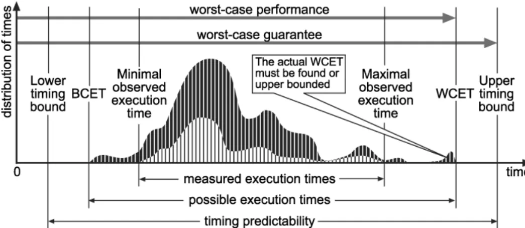
Figure 2.1: Graphical view of the execution times of a task, along with the relevant bounds [114]
In order to make the analysis sound, the worst-case path of the program and the worst-case conditions of the system have to be accurately found. Fig-ure [114] demonstrates an example where the meanings of the items are as follows:
• Measured execution times: Observed maximum/minimum execution times for the program. These could not be accurate, since the actual maximum/minimum execution times are very difficult to observe.
• BCET/WCET: Actual best and worst-case execution times.
• Upper/lower timing bound: Best and worst case execution times with a safety margin added.
• Possible execution times: The set of all possible execution times for all different program paths, inputs and initial hardware conditions.
• Timing predictability: The possible range of execution times after the safety margin has been added.
In Figure 2.1, the maximal observed execution time is lower than the WCET, which is under a different condition set. As described in [114], there are two solutions to eliminate the gap. The first solution is observing the flow graph, and ensuring full program coverage has been achieved. If this cannot be ensured, a block of code with an extremely high actual execution time may be missed. The second solution is testing all possible inputs and executing
the code with a sufficient number of iterations, in order to ensure all possible system states can be tested.
Even though measurement-based analysis is simpler than static analysis techniques, it is much more difficult to assert measurement-based analysis is sound, resulting from the unpredictability of system components, including I/Os, caches, external memory etc. In the following sections 2.2 and 2.3, we will specifically introduce the unpredictability caused by I/Os, and analyse the unpredictability in different types of system architectures.
2.2
Input and Output Systems (I/O Systems)
In computer and embedded architectures, input and output (I/O) systems transfer information between the main memory and the outside world [53]. An I/O system is composed of I/O devices (peripherals), I/O controllers and I/O drivers (carrying out the I/O request(s) through a sequence of I/O op-erations). Figure 2.2 illustrates an I/O system in a traditional single-core bus-based system, e.g. AHB Bus. In the figure, the shaded blocks represent the components of the I/O system.
0x000F FFFF 0x0000 0000 0xFC0 0 000 0 0x13FF FFFF 0x04FF FFFF 0x1000 0000 0x0000 0000 Local Memory Virtual Memory BlueTree Multiplexer 0x000F FFFF 0x0000 0000 Software Hardware User Mode Kernel Mod e Software Hardware User Mode Kernel Mod e Depth = j Finit e State Machine I/O Status Local Timer
GPIOCPU
Command
Queue
REG REG REG
Translation Module GPIOC PU GPIOC PU GPIOC PU REG Synchronization Module I/ O Pins SH
App
Guest OS (VM 1)
User Mode
Kernel Mode
RTOS
(FreeRTOS)
High Layer I/O Driver
App
Guest OS (VM 2)
User Mode
Kernel Mode
RTOS
(ucosII)
High Layer I/O Driver
App
Guest OS (VM 2)
User Mode
Kernel Mode
RTOS
(ucosII)
High Layer I/O Driver
App
Guest OS (VM 3)
User Mode
Kernel Mode
RTOS
(XilKernel)
High Layer I/O Driver
App
Guest OS (VM 3)
User Mode
Kernel Mode
RTOS
(XilKernel)
High Layer I/O Driver
Software
Hardware
BlueVisor
CPU (e.g.
Microblze)
Mmeory
UART
VGA
Ethernet
GPIOCP
PORT B PORT A Width: 32 Bits Depth: 64 FSM A BRAM Controll er Identifier of GPIO CMD 0 Length of GPIO CMD 0 GPIO Sub CMD 0 GPIO Sub CMD 1 Identifier of GPIO CMD 1 Length of GPIO CMD 1 GPIO Sub CMD 0 FSM B BRAM Controll er Register Control Signal
Hardware
Manager
Command Memory
VCDC
I/O Type
I/O
I/O VMM Low Layer Driver SPI-Flash Module SPI-FlashMany-Core System
Scheduler
I/O VMM Low Layer Driver Ethernet Module Ethernet I/O VMM Low Layer Driver VGA Module VGASynchronization
Processor
Legacy Guest OS
Legacy I/O Driver
VMM
Legacy Device
Emulation
VMM I/O Driver
VMM
Legacy Device
Emulation
VMM I/O Driver
I/O
Modified Guest OS
Frontend I/O Driver
VMM
Backend I/O Driver
Legacy I/O Driver
I/O
Modified Guest OS
Frontend I/O Driver
VMM
Backend I/O Driver
Legacy I/O Driver
I/O
Legacy Guest OS
Legacy I/O Driver
VMM
Legacy Device
Emulation
I/O Interface
VMM
Legacy Device
Emulation
I/O Interface
Host OS
Legacy I/O Driver
Host OS
Legacy I/O Driver
I/O
Software Hardware User Mode Kernel Mod eLegacy Guest OS
Legacy I/O Driver
VMM
Legacy Device
Emulation
I/O Interface
VMM
Legacy Device
Emulation
I/O Interface
Host OS
Legacy I/O Driver
Host OS
Legacy I/O Driver
I/O
R
R
R
R
R
R
R
R
M M MR
AR
AR
R
A M M MR
R
R
R
R
R
R
R
BlueVisor-I/O
UART VGA SPI
Flash Ethern et GPIOCP
D
D
R3
App
Guest OS (VM 1)
User Mode
Kernel Mode
RTOS
(FreeRTOS)
High Layer I/O Driver
App
Guest OS (VM 1)
User Mode
Kernel Mode
RTOS
(FreeRTOS)
High Layer I/O Driver
App
Guest OS (VM 2)
User Mode
Kernel Mode
RTOS
(ucosII)
High Layer I/O Driver
App
Guest OS (VM 2)
User Mode
Kernel Mode
RTOS
(ucosII)
High Layer I/O Driver
App
Guest OS (VM 3)
User Mode
Kernel Mode
RTOS
(XilKernel)
High Layer I/O Driver
App
Guest OS (VM 3)
User Mode
Kernel Mode
RTOS
(XilKernel)
High Layer I/O Driver
Software
Hardware
XXisor
Microblaze
ARM
CortexA9
Microblaze
ARM
CortexA9
CPUs
UART
VGA
SPI Flash
Ethernet
I/Os
GPIOCP
DDR3
DDR3
Many-Core System
μ0 μ1 μ2 μ3 μ4 μ5 μ6 μ7 DDR Backend DDR μ Many-Core System Processor /I/O 0x07FF FFFF BRAMs Individual External Memory Shared External MemoryT
CPU Memory I/O Controller I/O Device I/O Controller I/O DeviceApp
Guest OS (VM 1)
User Mode
Kernel Mode
RTOS
(FreeRTOS)
High Layer I/O Driver
Software Hardw are User M ode Kernel Mode User M ode Kernel Mode Application Application
Operating System (OS) I/O Driver
Figure 2.2: Structure of I/O System in a Conventional Bus-based System
This section is divided into two parts. Specifically, in Section 2.2.1 to Section 2.2.3, we introduce the basic idea of the three components in I/O systems. In Section 2.2.4, we discuss the reasons that I/O systems affect the
performance and real-time features of the whole system.
2.2.1 I/O Devices
In computer and embedded architectures, I/O device are computing facilities to provide user input/output, data storage and retrieval, network access capa-bilities, etc [53]. In order to make the controls and developments of different I/O devices to be general, classification of I/O devices is vital. In the thesis, we describe four types of commonly used classification for I/O devices.
According to the functionalities [92], I/O devices can be classified as:
• Input devices: Input information from a user to a computer, e.g. mouse and keyboard.
• Output devices: Output information from a computer to a user, e.g. screen and speaker.
• Input and output devices: Have functionalities of both input and output, e.g. network.
• Storage devices: Are used to store information, e.g. disks.
UNIX has proposed a widely used classification method of I/O devices: “depending on types of transmission, I/O devices are divided into character devices and block devices” [108] . Specifically, if the hardware device is ac-cessed by a stream of data, it is a character device (e.g. keyboards and UART). Otherwise, if the device is accessed randomly (non-sequentially), it is a block device (e.g. disk) [108].
As described in Section 2.1.2, the WCET of a program is always varied due to the specific hardware in both static analysis and measurement-based analysis. Therefore, even with the same system architecture and the same software, if an I/O device is replaced, the WCET of the program may be different. In general, the number of I/O devices increases the likelihood of the program’s WCET being affected.
Furthermore, I/O devices are also impact on the performance features of the whole system, because I/O devices are much slower than processors. Consider a common input device, a keyboard. Typing at 120 words per minute is equivalent to 10 characters per second, or 100 milliseconds between each character. A processor running at 2 GHz can execute approximately 200
million instructions during that time. If a blocking I/O operation happens, the processor will suffer from significant performance degradation.
2.2.2 I/O Controllers
In computer and embedded architectures, in order to handle I/O devices suf-ficiently and effectively, the following requirements are necessary [92]:
• Individual addressing of each device;
• Allowing devices to initiate communication with the processor;
• Method for transferring the bulk of data between I/O devices and mem-ory;
• Consistent method for programs to handle I/O from extremely different devices.
All these requirements suggest that it is not practical to connect the I/O devices directly to the processor. Each device or class of devices should have its own hardware interface connected to the processor [92] — interface module or I/O controller. Therefore, instead of handling thousands of different I/O devices, programs are only required to handle dozens of interface modules (I/O controllers). In Figure 2.2, an I/O controller acts as a direct interface between the system bus and the controlled I/O device. Figure 2.3 illustrates an example of general-purposed I/O controller.
As shown in Figure 2.3, a general-purpose I/O controller has two commu-nication interfaces, which are physically connected to a bus and I/O devices respectively:
• Bus-side Interface: Is responsible for buffering data to be transferred from the processor to an I/O device and allowing the processor to control the I/O device and read its status.
• I/O-side Interface: Is in charge of communicating with I/O devices, including data, status, control etc.
An I/O controller enables the following functionalities:
• Accepting requests from the processor to control and perform I/O oper-ations on the connected device(s);
• Controlling and managing the connected I/O device(s);
• Buffering received data until it is transferred to memory or the connected I/O device(s);
• Directly transferring data between I/O devices and memory.
Different I/O controllers have been widely adopted in different situations. According to the types of communication interface, I/O controllers can be clas-sified as serial I/O controllers or parallel I/O controllers. Figure 2.4 demon-strates an example of these two types of I/O controllers.
0x000F FFFF 0x0000 0000 0xFC0 0 000 0 0x13FF FFFF 0x04FF FFFF 0x1000 0000 0x0000 0000 Local Memory Virtual Memory BlueTree Multiplexer 0x000F FFFF 0x0000 0000 Software Hardware User Mode Kernel Mod e Software Hardware User Mode Kernel Mod e Depth = j Finit e State Machine I/O Status Local Timer GPIOCPU Command Queue
REG REG REG
Translation Module GPIOC PU GPIOC PU GPIOC PU REG Synchronization Module I/ O Pins SH
App
Guest OS (VM 1)
User Mode Kernel ModeRTOS
(FreeRTOS)
High Layer I/O Driver
App
Guest OS (VM 2)
User Mode Kernel ModeRTOS
(ucosII)
High Layer I/O Driver
App
Guest OS (VM 2)
User Mode Kernel ModeRTOS
(ucosII)
High Layer I/O Driver
App
Guest OS (VM 3)
User Mode Kernel ModeRTOS
(XilKernel)
High Layer I/O Driver
App
Guest OS (VM 3)
User Mode Kernel ModeRTOS
(XilKernel)
High Layer I/O Driver
Software
Hardware
BlueVisor
CPU (e.g.
Microblze)
Mmeory
UART
VGA
Ethernet
GPIOCP
PORT B PORT A Width: 32 Bits Depth: 64 FSM A BRAM Controll er Identifier of GPIO CMD 0 Length of GPIO CMD 0 GPIO Sub CMD 0 GPIO Sub CMD 1 Identifier of GPIO CMD 1 Length of GPIO CMD 1 GPIO Sub CMD 0 FSM B BRAM Controll er Register Control Signal Hardware Manager Command Memory
VCDC
I/O Type I/O I/O VMM Low Layer Driver SPI-Flash Module SPI-FlashMany-Core System
Scheduler I/O VMM Low Layer Driver Ethernet Module Ethernet I/O VMM Low Layer Driver VGA Module VGA Synchronization Processor Legacy Guest OSLegacy I/O Driver
VMM Legacy Device Emulation VMM I/O Driver VMM Legacy Device Emulation VMM I/O Driver I/O Modified Guest OS
Frontend I/O Driver
VMM Backend I/O Driver Legacy I/O Driver
I/O Modified Guest OS
Frontend I/O Driver
VMM Backend I/O Driver Legacy I/O Driver
I/O Legacy Guest OS
Legacy I/O Driver
VMM Legacy Device Emulation I/O Interface VMM Legacy Device Emulation I/O Interface Host OS
Legacy I/O Driver Host OS
Legacy I/O Driver I/O Software Hardware User Mode Kernel Mod e Legacy Guest OS
Legacy I/O Driver
VMM Legacy Device Emulation I/O Interface VMM Legacy Device Emulation I/O Interface Host OS
Legacy I/O Driver Host OS
Legacy I/O Driver
I/O
R
R
R
R
R
R
R
R
M M MR
AR
AR
R
A M M MR
R
R
R
R
R
R
R
BlueVisor-I/OUART VGA SPI
Flash Ethern et GPIOCP D D R3
App
Guest OS (VM 1)
User Mode Kernel ModeRTOS
(FreeRTOS)
High Layer I/O Driver
App
Guest OS (VM 1)
User Mode Kernel ModeRTOS
(FreeRTOS)
High Layer I/O Driver
App
Guest OS (VM 2)
User Mode Kernel ModeRTOS
(ucosII)
High Layer I/O Driver
App
Guest OS (VM 2)
User Mode Kernel ModeRTOS
(ucosII)
High Layer I/O Driver
App
Guest OS (VM 3)
User Mode Kernel ModeRTOS
(XilKernel)
High Layer I/O Driver
App
Guest OS (VM 3)
User Mode Kernel ModeRTOS
(XilKernel)
High Layer I/O Driver
Software
Hardware
XXisor
Microblaze
ARM
CortexA9
Microblaze
ARM
CortexA9
CPUs
UART
VGA
SPI Flash
Ethernet
I/Os
GPIOCP
DDR3
DDR3Many-Core System
μ0 μ1 μ2 μ3 μ4 μ5 μ6 μ7 DDR Backend DDR μ Many-Core System Processor /I/O 0x07FF FFFF BRAMs Individual External Memory Shared External MemoryT
CPU Memory I/O Controller I/O Device I/O Controller I/O DeviceApp
Guest OS (VM 1)
User Mode Kernel ModeRTOS
(FreeRTOS)
High Layer I/O Driver
Software Hardw are Da ta Kernel Mode User M ode Kernel Mode Application Application
Operating System (OS) I/O Driver
I/ O
Controll er I/ O Dev ice
Da ta
I/ O
Controll er I/ O Dev ice
(a) Serial Controller
0x000F FFFF 0x0000 0000 0xFC0 0 000 0 0x13FF FFFF 0x04FF FFFF 0x1000 0000 0x0000 0000 Local Memory Virtual Memory BlueTree Multiplexer 0x000F FFFF 0x0000 0000 Software Hardware User Mode Kernel Mod e Software Hardware User Mode Kernel Mod e Depth = j Finit e State Machine I/O Status Local Timer GPIOCPU Command Queue
REG REG REG
Translation Module GPIOC PU GPIOC PU GPIOC PU REG Synchronization Module I/ O Pins SH
App
Guest OS (VM 1)
User Mode Kernel ModeRTOS
(FreeRTOS)
High Layer I/O Driver
App
Guest OS (VM 2)
User Mode Kernel ModeRTOS
(ucosII)
High Layer I/O Driver
App
Guest OS (VM 2)
User Mode Kernel ModeRTOS
(ucosII)
High Layer I/O Driver
App
Guest OS (VM 3)
User Mode Kernel ModeRTOS
(XilKernel)
High Layer I/O Driver
App
Guest OS (VM 3)
User Mode Kernel ModeRTOS
(XilKernel)
High Layer I/O Driver
Software
Hardware
BlueVisor
CPU (e.g.
Microblze)
Mmeory
UART
VGA
Ethernet
GPIOCP
PORT B PORT A Width: 32 Bits Depth: 64 FSM A BRAM Controll er Identifier of GPIO CMD 0 Length of GPIO CMD 0 GPIO Sub CMD 0 GPIO Sub CMD 1 Identifier of GPIO CMD 1 Length of GPIO CMD 1 GPIO Sub CMD 0 FSM B BRAM Controll er Register Control Signal Hardware Manager Command Memory
VCDC
I/O Type I/O I/O VMM Low Layer Driver SPI-Flash Module SPI-FlashMany-Core System
Scheduler I/O VMM Low Layer Driver Ethernet Module Ethernet I/O VMM Low Layer Driver VGA Module VGA Synchronization Processor Legacy Guest OSLegacy I/O Driver
VMM Legacy Device Emulation VMM I/O Driver VMM Legacy Device Emulation VMM I/O Driver I/O Modified Guest OS
Frontend I/O Driver
VMM Backend I/O Driver Legacy I/O Driver
I/O Modified Guest OS
Frontend I/O Driver
VMM Backend I/O Driver Legacy I/O Driver
I/O Legacy Guest OS
Legacy I/O Driver
VMM Legacy Device Emulation I/O Interface VMM Legacy Device Emulation I/O Interface Host OS
Legacy I/O Driver Host OS
Legacy I/O Driver I/O Software Hardware User Mode Kernel Mod e Legacy Guest OS
Legacy I/O Driver
VMM Legacy Device Emulation I/O Interface VMM Legacy Device Emulation I/O Interface Host OS
Legacy I/O Driver Host OS
Legacy I/O Driver
I/O
R
R
R
R
R
R
R
R
M M MR
AR
AR
R
A M M MR
R
R
R
R
R
R
R
BlueVisor-I/OUART VGA SPI
Flash Ethern et GPIOCP D D R3
App
Guest OS (VM 1)
User Mode Kernel ModeRTOS
(FreeRTOS)
High Layer I/O Driver
App
Guest OS (VM 1)
User Mode Kernel ModeRTOS
(FreeRTOS)
High Layer I/O Driver
App
Guest OS (VM 2)
User Mode Kernel ModeRTOS
(ucosII)
High Layer I/O Driver
App
Guest OS (VM 2)
User Mode Kernel ModeRTOS
(ucosII)
High Layer I/O Driver
App
Guest OS (VM 3)
User Mode Kernel ModeRTOS
(XilKernel)
High Layer I/O Driver
App
Guest OS (VM 3)
User Mode Kernel ModeRTOS
(XilKernel)
High Layer I/O Driver
Software
Hardware
XXisor
Microblaze
ARM
CortexA9
Microblaze
ARM
CortexA9
CPUs
UART
VGA
SPI Flash
Ethernet
I/Os
GPIOCP
DDR3
DDR3Many-Core System
μ0 μ1 μ2 μ3 μ4 μ5 μ6 μ7 DDR Backend DDR μ Many-Core System Processor /I/O 0x07FF FFFF BRAMs Individual External Memory Shared External MemoryT
CPU Memory I/O Controller I/O Device I/O Controller I/O DeviceApp
Guest OS (VM 1)
User Mode Kernel ModeRTOS
(FreeRTOS)
High Layer I/O Driver
Software Hardw are Da ta Kernel Mode User M ode Kernel Mode Application Application
Operating System (OS) I/O Driver
I/ O
Controll er I/ O Dev ice
Da ta
I/ O
Controll er I/ O Dev ice
(b) Parallel˙Controler
Figure 2.4: Two types of I/O Controllers