2500 NETWORK DISPLAY UNIT
(NDU)
GLOSSARY OF STANDARD TERMS
The following abbreviations are used throughout this manual:
ACF:
Ancillary control facility.
"Ackd":
Display abbreviation for acknowledged condition.
AVF:
Alarm Verification Facility.
ALM:
Display abbreviation for alarm condition.
AS1668:
Australian Standard AS1668 specifying the use of mechanical
ventilation and air-conditioning in buildings.
FIP:
Fire Indicator Panel.
"Isol":
Display abbreviation for Isolated condition.
LCD:
Liquid Crystal Display.
LED:
Light Emitting Diode.
MANUFACTURERS DETAILS
APPROVALS: AUSTRALIAN STANDARD AS1603.4
SSL CERTIFICATE OF COMPLIANCE NUMBER 127
The 4100 Fire Indicator Panel is manufactured by:
Simplex International Time Equipment Pty Ltd
140 Old Pittwater Road
Brookvale N.S.W 2100 Australia
TABLE OF CONTENTS
COMPATIBLE ACTUATING DEVICES ... vii
SIMPLEX RANGE:... vii
HOCHIKI RANGE: CONVENTIONAL DETECTORS... vii
OLSEN RANGE: CONVENTIONAL DETECTORS... viii
APOLLO: CONVENTIONAL DETECTORS... viii
PANELECT/PANASONIC: CONVENTIONAL DETECTORS... viii
COMPATIBLE BATTERIES... ix
SPECIFICATION... x
GENERAL... x
EXPANSION MODULES... x
INDICATORS AND DISPLAY ... xi
KEYPAD CONTROLS... xi
SOFTWARE FEATURES ... xii
SECTION 1 - SYSTEM OVERVIEW ... 1
1.1 INTRODUCTION TO NETWORKING... 1
1.2 SYSTEM INTRODUCTION... 2
1.2.1 4120 Fire Indication Panel ... 2
1.2.2 2500 Network Display Unit... 3
1.2.3 2500 NDU with Status Command Centre ... 4
1.3 SYSTEM OPERATING DESCRIPTION... 4
1.3.1 Operator Log In/Log Out Procedures ... 5
1.3.1.1 Access Level Log-In Procedure... 6
1.3.1.2 Access Level Log Out Procedure... 7
1.3.2 HANDLING ABNORMAL CONDITIONS ... 7
1.3.2.1 The <DISPLAY TIME> Key... 9
SECTION 2 - ALARM CONDITIONS ... 10
2.1 GLOBAL ACKNOWLEDGE OPERATION DURING ALARM CONDITIONS ... 10
2.2 INDIVIDUAL ACKNOWLEDGE DURING ALARM CONDITIONS ... 12
2.3 ESSENTIAL ALARM CONDITION KEYS ... 13
2.3.1 Alarm Ack (Acknowledge)... 13
2.3.2 System Reset ... 13
2.4 HOW TO ISOLATE / DE-ISOLATE A ZONE... 14
2.5 HOW TO ISOLATE / DE-ISOLATE INDIVIDUAL DEVICES... 16
2.5.1 Disabling Individual Points/Devices ... 16
2.5.2 Enabling Individual Points/Devices ... 17
SECTION 3 - FAULT CONDITIONS ... 19
3.5FAULT INDICATIONS FOR TRUEALARM™ SENSORS... 22
3.5.1 Dirty Fault Indication ... 22
3.5.2 Excessively Dirty Fault Indication... 23
3.5.3 Self Test Abnormal Fault Indication ... 23
SECTION 4 - RS-232 INTERFACE... 24
4.1 RS-232 PORT ACCESS LEVELS ... 24
4.2 THE VIDEO TERMINAL ... 24
4.2.1 CRT Function Key Definitions... 25
4.2.2 Set-Up Procedure... 25
4.3 CRT SCREEN DISPLAYS... 25
4.3.1 CRT Main Menu Screen ... 26
4.3.2 Acknowledge Screen ... 26
4.3.3 Log In Screen ... 27
4.3.4 Historical Log Screen ... 28
4.3.5 Status Screen ... 29
4.4 THE SYSTEM PRINTER ... 30
SECTION 5 - MAPNET II
®... 31
5.1 MAPNET II®ALPHANUMERIC DISPLAYS ... 31
5.2 MAPNET II®POINT ADDRESSING... 31
5.2.1 How to Display a MAPNET II® System Point... 31
5.2.2 What To Do If a MAPNET II® Point Will Not Reset ... 31
SECTION 6 - ADVANCED FUNCTIONS ... 32
6.1 CONTROL KEYS ... 32
6.2 FUNCTION KEYS ... 33
6.3 HOW TO SET TIME AND DATE ... 33
6.4 HOW TO ESCAPE FROM MENU ... 35
6.5 POINT CONTROL WITH THE FUNCTION KEY ... 35
6.6 DISPLAY/ACTION KEYS ... 36
6.6.1 Function Key Operation ... 37
6.6.2 MENU Key... 37
6.6.3 PREVIOUS Key... 38
6.6.4 NEXT Key... 38
6.6.5 LAMP TEST Key ... 38
6.6.6 Action Keys ... 38
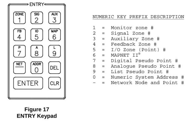
6.6.7 Entry Keypad ... 39
6.7 HOW TO ENTER A PREFIX ... 39
6.8 HOW TO DISPLAY MAPNET II®POINT STATUS ... 41
6.9 HOW TO DISPLAY THE SENSITIVITY OF A TRUEALARM™ SENSOR ... 43
6.10 ADDITIONAL KEYS ... 45 6.10.1 Enter... 45 6.10.2 Clear... 45 6.10.3 Hyphen ... 45 6.10.4 Delete ... 46 6.11 POINT SELECTION ... 46
6.11.1 Selecting Points Using Lists ... 46
6.11.2 Selecting Points Using the Keyboard... 46
6.13 POWER UP SEQUENCE ... 48
SECTION 7 - SYSTEM TEST PROCEDURES ... 49
7.1 LAMP TEST ... 49
7.1.1 Walk Test™... 49
7.2 HOW TO TURN A POINT OFF ... 49
7.3 HOW TO TURN A POINT ON ... 50
7.4 HOW TORETURN A POINT TO AUTO ... 51
7.5 WHAT TO DO IN CASE OF SYSTEM MALFUNCTION ... 52
SECTION 8 - MAINTENANCE PROCEDURES... 53
8.1 WEEKLY TESTS... 53
8.2 MONTHLY TESTS ... 54
PANEL DETAILS
panel sticker
4100 Panel supplied by
Installation location
Contract/Job Number
As installed FIP System
drawing number
Panel Installation date
Panel Commissioned date
Maintenance Company
Telephone
COMPATIBLE ACTUATING DEVICES
The following detectors have been approved as compatible devices for use with the
4100 FIP.
SIMPLEX RANGE:
1)
Analog Addressable Sensors
4098-9701
High / Very High sensitivity Photoelectric smoke
4098-9716
Ionisation smoke
4098-9731
Type A / Type B Heat
4098-9781
Addressable LED Indicating base
4098-9782
Addressable LED Indicating base with Sounder
4098-9783
Addressable LED Indicating base with Relay driver
2)
Conventional Detectors
4098-9413
Heat detector Type A
4098-9414
Heat detector Type B
4098-9415
Heat detector Type C
4098-9416
Heat detector Type D
2098-9201
Photoelectric smoke detector
2098-9576
Ionisation smoke detector
2098-9211
Universal base.
HOCHIKI RANGE: Conventional Detectors
DCA-B-60R MK V
Type A heat detector
DFE-60B
Type B heat detector
DCA-B-90R MK 1
Type C heat detector
DFE-90D
Type D heat detector
DFG-60BLKJ
Type B heat detector
SPA-AB
Beam type smoke detector
SIH-AM
Ionisation smoke detector
SLK-A
Photoelectric smoke detector
SLG-AM MK 1
Photoelectric smoke detector
HF-24A MK 1
Ultraviolet smoke detector
YBC-R/3A
Plain - non indicating base
YBF-RL/4AH4
LED Indicating base
OLSEN RANGE: Conventional Detectors
B111B
Beam type smoke detector
C24B
Ionisation smoke detector
C29B
Ionisation smoke detector
FW81B
Heat detector cable
P24B
Photoelectric smoke detector
P29B
Photoelectric smoke detector
R24B
Dual spectrum infrared flame detector
T54B
Probe type heat detector type E
T56B
Heat detector types A,B,C,D with Z55B base
T56B
Heat detector types A,B,C,D with Z54B base
V41B/V42B
Ultraviolet flame detector
APOLLO: Conventional Detectors
Heat detector
Type A
Heat detector
Type B
Heat detector
Type C
Heat detector
Type D
Series 20
Photoelectric smoke detector
Series 30
Ionisation smoke detector
PANELECT/PANASONIC: Conventional Detectors
PFS-A
Heat detector Type A
PFS-B
Heat detector Type B
PFS-C
Heat detector Type C
PFS-D
Heat detector Type D
PFS-P
Photoelectric smoke detector
PFS-I
Ionisation smoke detector
COMPATIBLE BATTERIES
The following series of batteries are compatible with the 4100 FIP:
(1)
Power-Sonic PS12 series
(2)
Sonnenschien A200 series
(3)
Sonnenschien A300 series
(4)
Yuasa NP series
SPECIFICATION
GENERAL
System Capacity
1,000 points of addressable input / output devices or
conventional zones.
Cabinet Size(mm)
Dependent on system configuration
Cabinet Material
1.5mm Mild grade steel
Cabinet Finish
Powder coated
Cabinet Colour
Magnolia Ripple
Mounting Wall
mount
Mains Input
240V AC, +6%,-10%, 50Hz
Internal Power Supply
24V DC @ 6.5A
Standby Battery
24V sealed lead acid up 110Ah
Battery Charger
27.6V DC (nominal) @ 3.5A,
PSU Supervision
Charger high/low, Battery low/fail
Temperature
-5 C to 45 C
Humidity
10% to 90% RH non-condensing.
EXPANSION MODULES
Maximum Number
119 modules
4100 - 5002
Conventional zone module
Eight zone circuits per module
Supports standard 20V detectors plus normally open
contact devices
4100 - 3003
Eight CPU controlled auxiliary relays per module
SPDT contacts rated for 3 amps @ 24VDC or 30VAC
4100 - 0113
RS-232 / 2120 Communications Module
Provides two RS-232-C outputs for remote printers
and/or CRT
Five RS-232-C ports maximum per 4100 system
Can be configured for communication with a host 2120
system
Can be configured as a Computer Port for
communications to a remote system i.e. BMS or BAS
Systems
EXPANSION MODULES - Continued
4100-6011
4120 Network Interface Module
RS485 Communications
Optional Fiber Optics Media Card
4100 - 0110
MAPNET® TRUEALARM™ Addressable Loop Module
Up to 127 MAPNET Addressable devices or TrueAlarm
Analog Sensors
Up to 10 MAPNET Loop Cards per 4100 system
Supports MAPNET Short Circuit Line Isolator Modules
4100 - 0304
Remote Unit Interface Module
Provides a supervised serial communications channel to
remotely located distributed Miniplex® Transponders
and LCD Annunciators
Up to 32 distributed Miniplex® Transponders and/or LCD
Annunciators per 4100 system
4100 - 3024
24 Relay Input / Output Relay Motherboard
24 CPU controlled relays
Each of the 24 relays can be individually configured as
either an input or an output
SPST contacts rated for 0.5 amps @ 24VDC or 30VAC
4100 - 0301
64/64 LED / SWITCH Controller
Interfaces up to 64 LEDs and 64 switches to the master
controller for front panel annunciation
INDICATORS and DISPLAY
Zone Status
2 line by 80 character backlight Liquid Crystal Display
with adjustable contrast control
LED Status Indicators
Common Alarm, Fault and Isolate
Bell Isolated, ACF Isolated, Mains Power ON
Audible Buzzer
Alarm And Fault Indications
Keypress feedback
KEYPAD CONTROLS
SOFTWARE FEATURES
* WALK TEST System Test
* 4 Operator Access Levels
* 600 Event Historical Logging
* Zone selectable Alarm Verification
* Individual Circuit Disconnect / Isolate
. .
INDICATOR. - PRE SS "A LARM SILEN CE". AC K
FIRE S YSTEM SIGN ALS POWER ON RE SET AC K
. .
INDICATOR. - PRE SS "A LARM SILEN CE". AC K
FIRE S YSTEM SIGN ALS POWER ON RE SET AC K
. .
INDICATOR. - PRE SS "A LARM SILEN CE". AC K
FIRE S YSTEM SIGN ALS POWER ON RE SET AC K
. . INDICATOR. - PRE SS "A LARM SILEN CE". AC K
FIRE S YSTEM SIGN ALS POWER ON RE SET AC K
. . INDICATOR. - PRE SS "A LARM SILEN CE". AC K
FIRE S YSTEM SIGN ALS POWER ON RE SET AC K
Token
Figure 1
SECTION 1 - SYSTEM OVERVIEW
1.1
INTRODUCTION TO NETWORKING
The Simplex 4120 Network is a system of individual Fire Alarm Control Panels communicating on a loop as a Peer-to-Peer network (refer Figure 1). This means that every network panel has an equal chance of putting a message out on the network. Each panel with direct communications into the 4120 Network is defined as a “Node”. Each node can maintain the status and control of its own dedicated circuit points while monitoring and controlling activity at other locations.
The communications scheme used by the network is based on Token Ring Communications Protocol. In Token Ring communications, an electronic data “flag” or “token” is passed from one node to the next. The node that holds the token is the only one permitted to talk on the network. A node that has no messages or requests for the network simply passes the token onto the next node. Thus, every node has an equal chance of putting a message out on the network when needed.
A 4120 Network Node can be any of the following:
• 4120 Fire Alarm Control Panel
• 4120 Voice Fire Alarm Control Panel
• 4120-8010 Miniplex Control Panel
• 4120-8511 Universal Transponder (UT)
• 4120 Status Command Centre
• 4120-8821 2500 NDU with Command Centre
An existing 4100 Fire Alarm Control Panel or Universal Transponder can also be included in the network by installing a 4120-0140 RS-485 Network Interface Card into a panel slot in the existing unit and configuring the panel to accept the card.
Network information in sequentially transmitted from one node to another. At each node, the network message is captured and either retransmitted as received, or modified before retransmission to provide the network with a status update. The ability of the message to circulate through the network defines network status and allows the nodes to respond accordingly.
If a node goes off-line, its network interface module will bypass that connection until the node is back on-line. If the wires between nodes short, open or have any other form of communication problem, the network will isolate that section of wiring. A node that cannot retransmit a message to the next node will transmit back to the previous node to maintain communications and to notify the network of the node status.
In the event of multiple wiring problems, the remaining nodes will effectively “regroup” and establish new, smaller “sub-networks” that will maintain communications among the active nodes.
1.2
SYSTEM INTRODUCTION
A 4120 Fire Alarm Network System may comprise of the following Network Fire Alarm panels, depending upon total network point capacity:
• 4120 Fire Alarm Panel for system with up to 1,000 network points
• 4120 Network Display Unit (NDU) with Status Command Centre, for systems with up to 2,500 network points.
1.2.1 4120 Fire Indication Panel
The Simplex 4120 is a microprocessor based Fire Alarm Control Panel which uses the latest in life safety technology and is certified to Australian Standard AS1603.4. The 4120 Fire Indicator Panel has the capacity to monitor and control up 1,000 devices . These devices can either be conventional zones of detectors or analogue addressable devices. In the event of AC mains loss, standby batteries provide a backup 24VDC supply.
The 4120 FIP uses a micro-controller with a Flash EPROM, allowing the use of laptop computer to download custom program changes directly into the 4120 for easier on-site job changes . Battery-backed RAM has been added to maintain important historical data, even during a complete power-down of the system.
The 4120 also uses a switching power supply to provide up to 7 Amps of power at 24 VDC for load devices and system operation, plus up to 3 Amps for battery charging responsibilities. In addition, this power supply can communicate directly with the Master Controller via internal serial communications, reporting such data as system voltage and current usage and battery charging information.
The 4120 FIP has been designed to be a custom, factory configured system and when delivered to the job site, becomes a totally field editable and configurable system in response to unforeseen job changes.
To provide maximum efficiency in performing primary fire alarm functions, the 4120 Operator Interface Panel makes visible only the indication and interaction keys required in an emergency situation .
Alarm, Isolation and Fault conditions are indicated at the operator’s panel by dedicated LEDs and a Piezo sounder. Each of these system conditions has a dedicated acknowledge button.
A 2 line, 80 character alphanumeric LCD display is used to annunciate a 40 character custom label message per device or circuit, the device point type (smoke detector, manual call point, etc.), the current status of the device or circuit (alarm, fault etc.) as well as operator prompts for acknowledging status changes or inputting commands.
The alphanumeric display will show various prompts and labels which are used to guide the user through a sequenced operation for each abnormal condition.
The 4120 can be programmed to perform a "global acknowledge" where a single key press of the appropriate acknowledge button will silence the piezo for all points in that condition. The 4120 can also be programmed for individual acknowledgment of each point in an abnormal condition as well as its restoration.
After an alarm condition, the system can be restored to normal operating mode by depressing the " System Reset" button. To serve as a "fault reminder" when a fault condition remains in the system and audible fault signal has been silenced, the piezo will resound at a specified time interval to alert the user that the fault condition remains and needs rectification.
The operator’s interface door provides easy access to additional operator controls and LED indicators. The depth of the operator’s interaction is determined by four Security Access levels.
Level 1 is the lowest level and allows the operator to perform routine actions. Level 4 on the other hand is the highest level and only provides for the most sensitive operations by an authorised service technician. Each of these access levels is governed by a passcode chosen at order entry or as edited by a Simplex service technician.
The "FUNCTION KEYS", "DISPLAY/ACTION" keypad, and the "ENTRY" keypad are the operator interface sections which provide, in a self -directing manner, operations non-essential in a fire emergency situation.
These operations include items such "ISOLATE" or "DE-ISOLATE" a circuit, turn a control point "ON" or "OFF", and menu items such as "SET TIME AND DATE", "DISPLAY HISTORICAL LOGS", etc. Programmable "CONTROL" keys and their associated LEDs can be programmed to perform a variety of functions and can be individually passcode protected. These "CONTROL" keys are typically used for alarm and fault test, ACF Isolate, Brigade test and battery test functions.
1.2.2 2500 Network Display Unit
The Simplex 2500 Network Display Unit (NDU) is a network annunciator and manual system/point controller for a 4120 Network. The NDU provides alphanumeric annunciation for up to 2,500 network points and/or point lists and can be programmed to function as the network master controller for Silence, Acknowledge and System Reset.
Standard features include an alphanumeric display exactly like the 4100 Fire Alarm Control Panel and more memory to achieve 2,500 point capacity.
The increased memory size provides 600 alarm and 600 fault event history logs, twice the size of any other 4120 or 4100 model. The 2500 NDU can drive up to 31 serial LCD Annunciators on one optional Remote Unit interface (RUI) card. In addition, the NDU can have up to five RS-232 ports for printers and CRT/Keyboards.
1.2.3 2500 NDU with Status Command Centre
The 2500 NDU with Status Command Centre combines the 2500 NDU with a custom selection of modular LED and/or LED and control switch assemblies that provide a dedicated monitor and control interface. Voice modules are available with this model to configure this panel into a Voice Command Centre.
The NDU with Status command Centre is actually two nodes in one cabinet assembly. The NDU occupies the top bay of the unit and the Command Centre occupies the rest.
1.3
SYSTEM OPERATING DESCRIPTION
NOTE: This document covers the operating procedures for a typical 4120 FIP Applications
will vary due to custom programming and local code requirements.
An alphanumeric display on the 4120 FIP Operator Interface Panel (Figure 2) indicates the condition of the system. The alphanumeric display shows the various labels and prompts which guide the user through a sequenced operation for each abnormal condition.
Figure 2
4100 Operator Interface Panel
(Panel Access Door Closed)
Audible and visual indication are provided to indicate abnormal conditions, when they exist throughout the network.
The 4120 FIP Operator Interface Panel, hereinafter called the interface panel, shows the following under normal conditions:
• Green "POWER ON" LED ON (indicating that AC power is applied).
• All other interface panel indications OFF.
• Alphanumeric display states that the SYSTEM IS NORMAL followed by the time and date as shown below.
SIMPLEX AUSTRALIA SYSTEM IS NORMAL
08:23:43 MON 25 JAN 95
Abnormal conditions are indicated on the interface panel by flashing the alarm, isolate, or fault LED and sounding the tone-alert. The alphanumeric display provides information as to the point status (alarm, isolated, and fault), type of alarm (smoke detector, pull station, etc.), number of abnormal conditions in the system, and a custom label. Alarm, isolate and fault conditions each have their respective acknowledge key. Pressing the appropriate acknowledge key will silence the tone-alert. However, the LED indicating the abnormal condition remains illuminated until all initiating devices are restored to normal.
If your system is configured with a CRT or printer option, point status is also displayed on these devices. The CRT option controls various system functions. It can also acknowledge system status changes, silence alarm signals, and perform system reset procedures.
When a monitor zone or device senses an Alarm condition (heat, smoke, manual call point), this is relayed to the 4120 FIP and displayed on the Interface Panel by the SYSTEM
ALARM LED flashing, tone-alert sounding, and zone alarm LED turning on. In addition,
depending on the nature of the alarm condition, the fire trip relays will be activated, brigade call relay will turn ON and various programmed events will occur.
When the 4120 FIP senses a malfunction within the system (loss of power, hardware failure, zone fault, etc.) a FAULT condition is annunciated. The tone-alert turns on steady, the FAULT LED will flash .
All abnormal conditions must be acknowledged by pressing the <ACK> key under the appropriate flashing LED.
The system has "re-sound" capability. If, after silencing the tone-alert, the system detects another abnormal condition, the zone with the abnormal condition will be indicated on the panel’s alphanumeric display, the appropriate indicator will again flash and the tone-alert will sound.
To provide maximum efficiency in performing primary fire alarm functions, the front panel access door covers all keys except those required for indication and interaction for emergency situations.
1.3.1 Operator Log In/Log Out Procedures
Various functions may be passcode protected to prevent access by unauthorised personnel. Passcodes are provided to the user during system installation. To change or receive additional information concerning your passcodes, contact your local Simplex Branch Office.
1.3.1.1 Access Level Log-In Procedure
To Log on, perform the following procedure. 1. Obtain the appropriate passcode information. 2. Open the interface panel access door.
3. Press the <MENU> key on the DISPLAY/ACTION keypad on the right side of the interface panel. The following is displayed.
Press <NEXT> or <PREVIOUS> to scroll
Change Access Level?
4. Press the <ENTER> key on the DISPLAY/ACTION keypad the following is displayed.
F1=Login F2=Logout
CURRENT ACCESS LEVEL = 1
5.
Press the <F1> key (above the alphanumeric display). The display shows the
following.
Enter a Passcode followed by <ENTER>
6. Enter the passcode. Press the <ENTER> key on the Entry keypad. For security reasons, an "X" is displayed for each digit of your passcode, as shown below.
Enter a Passcode followed by <ENTER>
XXX
If the passcode is correct, the following is shown.
Enter a Passcode followed by <ENTER>
ACCESS GRANTED
After a brief pause, the display shows the granted access level, such as level 3 access message shown below.
F1=Login F2=Logout
CURRENT ACCESS LEVEL = 3
7. Press <CLR> key on the ENTRY keypad twice. The display shows system status, as shown below.
SIMPLEX AUSTRALIA SYSTEM IS NORMAL
08:23:43 MON 25 JAN 95
1.3.1.2 Access Level Log Out Procedure
IMPORTANT
FAILURE TO LOG OUT ALLOWS UNAUTHORISED PERSONNEL ACCESS TO THE VARIOUS PASSCODE PROTECTED FUNCTIONS. IF NO KEYPAD ACTIVITY IS DETECTED FOR TEN MINUTES, THE SYSTEM WILL RETURN TO LEVEL 1 ACCESS.
To Log out, perform the following procedure.
1. Press the <MENU>key on the DISPLAY/ACTION keypad.
2. Press the <NEXT> key until the menu prompt "CHANGE ACCESS LEVEL?" appears on the alphanumeric display.
3. Press <ENTER> on the ENTRY keypad.
4. Press the <F2> key (above the alphanumeric display) to Log Out.
5. Press the <CLR> key on the ENTRY keypad to escape from the Main Menu.
1.3.2 HANDLING ABNORMAL CONDITIONS
If an abnormal condition occurs, at least one of the LEDs (alarm, isolate or fault) will start flashing, and the tone-alert will sound. The panel will display the total number of abnormal conditions present in the system. At a glance, the user knows how serious the situation might be by reading the number of abnormal conditions displayed, such as the single alarm shown below.
The 4120 FIP also creates a "List" when abnormal conditions exist. The list contains the number of abnormal conditions present in the system. The user pushes the <ACK> keys to view the abnormal condition list, reviews each condition, silences the alarms, views the alarm list, restores affected devices, and resets the panel, if required.
When an abnormal condition has been detected by the system, the appropriate LED will be flashing and the tone-alert will be beeping for alarm conditions. The tone-alert will be on steady for isolate and fault conditions.
Pressing the appropriate <ACK> key (under flashing LED) will display the first acknowledged condition in the appropriate list. The <ACK> function may be passcode protected. If the user has insufficient privilege to acknowledge the condition, a message will indicate the problem, but allow the user to view the points without acknowledging them. If the user has sufficient privilege to acknowledge the condition, a message is displayed informing the user that the condition has been acknowledged. (See sections on Operator Access Levels and Log On Procedures).
The system is configured with Global Change Acknowledge such that one press of an <ACK> key will globally acknowledge every abnormal point in the system. If all the points were acknowledged in this manner, an appropriate message is then displayed . When the fault condition clears, the abnormal condition will automatically clear. Alarm conditions must be acknowledged.
The acknowledge function imposes a delay of at least one second between point acknowledgments. This minimum delay is to prevent the user from pressing the <ACK> key without viewing the information displayed on the alphanumeric display.
After all points have been acknowledged, the LEDs will be on steady and the tone-alert will be silenced. The total number of alarm, isolate, and fault conditions will be shown on the alphanumeric display along with a prompt to press the <ACK> key for point review. Subsequent pressing of an <ACK> key will scroll through the selected list in chronological order.
After 30 seconds of keypad inactivity, the total number of abnormal conditions will again be shown on the alphanumeric display. Pressing the <ACK> key will select a list for review. The first point to be displayed will either be the first acknowledged point in the list, or the first point in the list if all are acknowledged.
Alarm, isolated and fault lists are displayed in chronological order. A message will indicate when the end of a list has been reached. The list message will contain the total number of abnormal conditions, such as the single alarm shown below.
***ALARM*** Press ACK to review.
1.3.2.1 The <DISPLAY TIME> Key
The <DISPLAY TIME> key is used to view the time of day when the abnormal condition occurred. By viewing the time for each abnormal condition occurrence, fire brigade personnel can determine the path and possible cause for each abnormal condition.
Note that the <DISPLAY TIME> key only displays time for existing abnormal conditions. The red <DISPLAY TIME> key works for any point currently in an alarm, isolate or fault condition. The time/date information is obtained from the historical log and is shown on the alphanumeric display. In situations where multiple conditions are present, you can simply push one key to review the time that each abnormal condition occurred. An example of an alarm condition is shown below.
TOWER BUILDING 3RD FLOOR
SMOKE DETECTOR ALARM
If the <DISPLAY TIME> key is pressed and held down, the display shows the alarm information, as shown below. This information is only displayed while the <DISPLAY TIME> key is held down.
TOWER BUILDING 3RD FLOOR
ALARM AT 19:56:32 MON 25 JAN 95
When the <DISPLAY TIME> key is released, the display will revert back to its original label and status.
To display alarm information, perform the following steps.
1. Ensure that the point to be checked is shown on the alphanumeric display by pressing the appropriate <ACK> key.
2. Press and hold in the <DISPLAY TIME> key. Information concerning the abnormal condition (alarm, isolate or fault) is displayed.
3. Press the appropriate <ACK> key to display the next condition change. 4. Repeat steps 2 and 3 above, as required.
NOTE: This key will not work for points directly entered into the system via the keypad (e.g.
SECTION 2 - ALARM CONDITIONS
When an alarm condition is detected by the 4120 FIP, it is indicated by the following:
• Red "ALARM" LED is flashing.
• Tone-alert is pulsing.
• LEDs on the local annunciator may illuminate.
• Alphanumeric display will show an alarm condition.
***ALARM*** Press ACK to review.
ALARMS = 1 ISOLATED = 0 FAULT = 0
The display has one red LED which is used to indicate an alarm condition. When an alarm occurs, the red LED flashes, the tone-alert pulses, and an alarm message is displayed on the alphanumeric display. The red LED will glow steady and the tone-alert is silenced upon activation of the <ALARM ACK> key. When the alarm condition clears, the red LED will turn off and the alarm will be removed from the alarm list. Once alarm conditions have been cleared, Alarm events can be reviewed by examining the historical alarm log.
2.1
GLOBAL ACKNOWLEDGE OPERATION DURING ALARM CONDITIONS
(Red Alarm Light Flashing And Tone Alert Pulsing)
Figure 3
Operator Interface Panel Showing Alarm Condition
A GLOBAL ACKNOWLEDGE of a System Alarm Condition is accomplished in the following manner.
1. Unlock and open the panel door. The Fire Alarm Bell will now stop sounding due to the panel door being opened. Read the alphanumeric display. It shows the number of alarm conditions.
***ALARM*** Press <ACK> to review.
ALARMS = 1 ISOLATED = 0 FAULT = 0
2. Press the <ALARM ACK> key. Read the alphanumeric display. The tone-alert is silenced and the display will show pertinent report information, such as shown below.
1ST FLOOR EAST WING ROOM 2 AZF1
SMOKE DETECTOR ALARM
The SYSTEM ALARM LED changes from flashing to steady ON, and all alarm conditions are acknowledged.
Pressing the <ALARM ACK> key scrolls through all the alarms in chronological order.
HOW TO SILENCE THE ALARM SIGNALS
Press the <ALARM SILENCE> key and read the display. The alphanumeric display will show signal status.
ALARM SILENCE IN PROGRESS . . .
HOW TO RESET THE SYSTEM
When the alarm condition has been cleared, restore or replace all affected devices
(MCP’s, smoke detectors, etc.) in accordance with the instructions provided with
each device.
Press the <SYSTEM RESET> key. After a delay, the system will return to normal
and the display should show the following:
2.2
INDIVIDUAL ACKNOWLEDGE DURING ALARM CONDITIONS
An INDIVIDUAL ACKNOWLEDGE of a System Alarm Condition is accomplished in
the following manner.
1. Unlock and open the panel door. The Fire Alarm Bell will now stop sounding due to the panel door being opened. Read the alphanumeric display. It shows the number of alarm conditions.
***ALARM*** Press <ACK> to review.
ALARMS = 1 ISOLATED = 0 FAULT = 0
2. Press the <ALARM ACK> key. Read and follow the instructions on the alphanumeric display. Pertinent report information is given as shown below.
1ST FLOOR EAST WING ROOM 2
Press ACK key to acknowledge ALARM
SMOKE DETECTOR ALARM
Press the <ALARM ACK> key again. Read the report data. Repeat this procedure to review all reports which are displayed in chronological order. The SYSTEM ALARM LED changes from flashing to steady ON, and all alarm conditions are acknowledged.
HOW TO SILENCE THE ALARM SIGNALS
Press the <ALARM SILENCE> key and read the display. The alphanumeric display will show signal status.
ALARM SILENCE IN PROGRESS . . .
HOW TO RESET THE SYSTEM
When the alarm condition has been cleared, restore or replace all affected devices (MCP’s, smoke detectors, etc.) in accordance with the instructions provided with each device.
1. Press the <SYSTEM RESET> key. After a delay, the SYSTEM ALARM LED will begin to flash and the tone-alert will begin its pulsing sound.
2. Press the <ALARM ACK> key twice. After a delay, system will return to normal and the display should show the following:
SIMPLEX AUSTRALIA SYSTEM IS NORMAL
8:23:43 MON 25 JAN 95
ALTERNATING LINES
2.3
ESSENTIAL ALARM CONDITION KEYS
The essential keys for alarm conditions are the <ALARM ACK>, <ALARM SILENCE> and the <SYSTEM RESET> keys. The remaining keys are concealed by the access door and are associated with advanced functions of the system. (See Advanced Functions Section 6.)
2.3.1 Alarm Ack (Acknowledge)
The <ALARM ACK> key is located directly under the SYSTEM ALARM LED. Pressing the <ALARM ACK> key (twice for Individual Acknowledge or once for Global Acknowledge) will cause the LED to change from flashing to a steady ON condition and silence the tone-alert. Pressing the <ALARM ACK> key will:
• Select the next unacknowledged alarm point in the list for display (Individual Acknowledge).
• Acknowledge the displayed point or acknowledge all points on the list (Global Acknowledge).
• Scroll the points chronologically after all points have been acknowledged.
2.3.2 System Reset
The <SYSTEM RESET> key is used to return the system to its normal state after an alarm condition has been cleared. When the <SYSTEM RESET> key is pushed, it will cause the latched circuits to clear automatically. All circuits include initiating devices, relays, indicating appliances, and all LEDs and indicators which are programmed to reset with the reset key. The message, "SYSTEM RESET IN PROGRESS", will be displayed when the <SYSTEM RESET> key is pressed.
With the Individual Acknowledge systems, when the alarm condition has reset, the SYSTEM ALARM LED flashes and the system requires that the <ALARM ACK> key be pressed. The message "SYSTEM IS NORMAL" followed by time and date should be displayed. This process will take about 45 seconds.
If a zone stays in alarm during the reset period, the message, "SYSTEM RESET IN PROGRESS", will be followed by the message:
If the system does not reset, no fire exists, and the display still shows an alarm, read the alphanumeric display to determine the type of device and the zone number in alarm. Follow local procedures to investigate the area of the building with the alarm. Look for devices still in alarm (manual call points, smoke detectors, etc.). Most devices latch until they are reset, either by the system or manually.
2.4
HOW TO ISOLATE / DE-ISOLATE A ZONE
If a device will not reset, the user may elect to perform the ISOLATE procedures listed below.
IMPORTANT
IT IS IMPORTANT TO REMEMBER THAT ONCE A POINT IS ISOLATED, IT WILL NOT PROVIDE FIRE PROTECTION. REPAIR/REPLACE THE DEVICE AS SOON AS POSSIBLE. ONCE REPAIRED, THE POINT SHOULD BE ENABLED AS SOON AS POSSIBLE.
If a device does not reset, the user may isolate the device/point causing the abnormal condition. This point must first be identified. This can be accomplished by reading the alphanumeric display while pressing the <ALARM ACK> key. The point can then be isolated by using the individual zone ISOLATE toggle switches as described below :
Press down the ISOLATE toggle switch next to the zone or point to be isolated - refer Figure 4, e.g. ( AZF1 1st Floor East Wing Room 23 ).
Once the toggle switch has been depressed, the yellow ISOLATE LED adjacent to the toggle switch will light ,indicating that the point or zone is now isolated.
The display will indicate a ISOLATED condition, until the isolated point has been de-isolated.
When a zone is isolated via the zone isolate switches , the condition is indicated on the main 4100 FIP as follows:
• Yellow "SYSTEM ISOLATE" LED is flashing.
• Tone-alert is on steady.
• Alphanumeric display shows the following:
**ISOLATIONS** Press ACK to review.
ALARMS = 0 ISOLATED = 1 FAULT = 0
1. The panel has a yellow isolate LED which will light whenever an isolation is present in the system. When a zone is isolated, the LED will flash, the tone-alert sounds steady, and a fault message will be displayed on the alphanumeric display. The isolate LED will glow steady and the tone-alert silences when the <ISOLATE ACK> key is pressed. 2. To de-isolate the point or zone, either depress or lift the toggle switch (refer Figure 4) ,
the yellow LED will turn off and the point or zone will be de-isolated.
3. Once all faults have been removed from the system, the display will read SYSTEM NORMAL.
4. Repeat steps 1 and 2 to isolate the required zones.
Note: Any time a zone is isolated, the event is recorded in the fault log.
As an alternative to isolating a zone of devices, the user may isolate individual devices in a zone.
2.5.1 Disabling Individual Points/Devices
If a device does not reset, you may disconnect the device/point causing the alarm condition. However this point must first be identified as follows:
1. Press the <ALARM ACK> key and read the alphanumeric display on the interface
panel.
2. Open the Operator Panel "Access Door" to expose the additional keys which are available for advanced functions. Then disable the identified alarm point with the
<DISABLE> key. If the <DISABLE> key is passcode protected, perform the Log On
procedure before performing the Isolate procedure. (Refer Section 3.1 Operator Log IN/OUT procedure).
The <DISABLE> key press removes power to any displayed monitor point. Thus disabling a point causes a fault condition to be displayed.
To isolate a point, perform the following procedure:
1. Open the Operator Interface Panel access door.
2. Press the <ALARM ACK> key until the point to be isolated is shown on the alphanumeric display, as shown below
M1-1 1ST FLOOR EAST WING ROOM 2 AZF1
SMOKE DETECTOR ALARM
3. Press the <DISABLE> key. The display shows the following message:
Press <ENTER> to ISOLATE
M1-1
4. Press the <ENTER> key. The display shows the action taken.
ACTION TAKEN
Note: The system indicates a Fault condition each time a point is isolated. Press the
<FAULT ACK> key as required. To clear the alarm condition, follow the System Reset Procedures.
If a device was isolated for any reason and has been restored, you can enable the point. This point must first be identified to the system. The isolated point causes a system fault condition which is continually shown on the display. This can be viewed by pressing the Fault <ACK> key and reading the display. The point can be enabled by using the <ENABLE> KEY. IF THE <enable> KEY IS PASSCODE PROTECTED, PERFORM "Log On Procedures" then continue.
To enable a isolated point, perform the following steps:
1. Press the <FAULT ACK> key until the point to be enabled is shown on the alphanumeric display, as shown below
M1-1 1st Floor East Wing Room 2 AZF1
SMOKE DETECTOR ISOLATE FAULT
2. Press the <ENABLE> key. The display shows the following message:
Press <ENTER> to ENABLE
M1-1
Note: Read the warning below before performing the following step
3. Press the <ENTER> key. The display shows the following message.
Please stand by...
M1-1 will ENABLE in 60 seconds
WARNING
If the zone is still in alarm, a WARNING is displayed which tells you that the system will sound an alarm if the timer (60 seconds) times out. TO ABORT THE ENABLE, PRESS THE <ISOLATE> KEY. If an alarm condition exists, the following is shown on the display.
**WARNING** Press <ISOLATE> to abort M1-1 will ALARM in 60 seconds
ENABLE COMPLETED
SECTION 3 - FAULT CONDITIONS
When a fault condition is detected by the 4120 FIP, the condition is indicated on the main 4120 Interface Panel as follows:
• Yellow "SYSTEM FAULT" LED is flashing.
• Tone-alert is on steady.
• Alphanumeric display shows the following:
**FAULT ** Press ACK to review.
ALARMS = 0 ISOLATED = 0 FAULT = 1
The panel has a yellow fault LED which will light whenever a fault is present in the system. When a fault occurs, the LED will flash, the tone-alert sounds steady, and a fault message will be displayed on the alphanumeric display. The fault LED will glow steady and the tone-alert silences when the <FAULT ACK> key is pressed.
When Global Acknowledge is used and the fault clears, the system automatically clears without user intervention. After approximately 30 seconds, the system should display "SYSTEM IS NORMAL” followed by time and date.
SIMPLEX AUSTRALIA SYSTEM IS NORMAL
08:23:43 FRI 11 MAR 95
When Individual Acknowledge is used, the tone-alert “re-sounds” when the fault clears. The <FAULT ACK> key must be pressed twice (once to change from Alarm Summary to actual point, and once to acknowledge the condition). After a delay, the alphanumeric display should indicate a normal system.
3.1
GLOBAL ACKNOWLEDGE OPERATION DURING FAULT CONDITIONS
A GLOBAL ACKNOWLEDGE of a fault condition is accomplished in the following manner. 1. Unlock and open the panel door. The alphanumeric display will show the fault
condition.
** FAULT ** Press <ACK> to review points
ALARMS = 0 ISOLATED = 0 FAULT = 1
2. Press the <FAULT ACK> key under the flashing yellow LED. The alphanumeric display will show area and type of fault. The tone alert will silence and the yellow LED will glow steady.
FIRST FLOOR EAST WING AZF1
FIRE MONITOR ZONE OPEN CIRCUIT FAULT
3. Read the alphanumeric display, then investigate the problem to determine its cause.
• Restore or replace the defective device in accordance with device instructions.
• The fault will automatically clear when the problem has been corrected.
• After a delay, the alphanumeric display should show:
SIMPLEX AUSTRALIA SYSTEM IS NORMAL
8:23:43 MON 25 JAN 95
3.2
INDIVIDUAL ACKNOWLEDGE OPERATION DURING FAULT CONDITIONS
An INDIVIDUAL ACKNOWLEDGE of a fault condition is accomplished in the following manner.
1. Unlock and open the panel door. The alphanumeric display will show the fault condition.
** FAULT ** Press <ACK> to review points
ALARMS = 0 ISOLATED = 0 FAULT = 1
2. Press the <FAULT ACK> key under the flashing yellow LED. Repeat this step and read the reports. The alphanumeric display will show area and type of fault. The tone alert will silence and the yellow LED will glow steady.
1ST FLOOR EAST WING ROOM 2
Press ACK key to acknowledge
FIRE MONITOR ZONE OPEN CIRCUIT FAULT
ALTERNATING LINES
3. Read the alphanumeric display, then investigate the problem to determine its cause. Restore or replace the defective device in accordance with device instructions.
Note: When the fault clears, the fault LED flashes and the tone-alert sounds steady.
4. Press the <FAULT ACK> key under flashing yellow LED. The alphanumeric display shows the system status.
5. Press the <FAULT ACK> key under flashing yellow LED again. After a delay, the alphanumeric display should show:
SIMPLEX AUSTRALIA SYSTEM IS NORMAL
8:23:43 MON 25 JAN 95
3.4
ESSENTIAL FAULT CONDITION KEYS
The essential keys for fault conditions are <FAULT ACK>, and the <SYSTEM RESET> keys. The remaining keys are concealed by the access door and are associated with
advanced functions of the system. (See Advanced Functions Section 6). Use of these
keys require advanced user skills.
3.4.1 Fault Acknowledge Key
The <FAULT ACK> key is used to scroll through the various displays on the alphanumeric display. It also controls the Fault LEDs and the tone-alert. The <FAULT ACK> key is located directly under the fault LED. Pressing the <FAULT ACK> key (twice for Individual Acknowledge or once for Global Acknowledge) will cause the LED to change from flashing to on steady and silence the tone-alert. When the <FAULT ACK> key is pressed, it will:
• Select the next unacknowledged fault point and display it on the alphanumeric display (Individual Acknowledge).
• Acknowledge the displayed point or acknowledge all points on the list (Global Acknowledge).
• Silence signals programmed to follow the Fault Acknowledge key.
• Scroll the points chronologically after all points have been acknowledged.
There are two types of acknowledges for the 4120 FIP: Global Acknowledge and
Individual Acknowledge. Each acknowledge type operates with the Fault Condition
in the following manner.
• When Global Acknowledge is used on the 4120 system, a single key press will acknowledge all fault changes in the system. If status change information is required, the user may review this data (after a delay) by pressing the <ACK> key and reading the
• When Individual Acknowledge is used and a fault condition has been acknowledged with the <ACK> key, and further unacknowledged fault conditions remain in the system, the tone-alert continues to sound and the next status change is shown on the alphanumeric display.
NOTE: Normally, points may not require acknowledgment and do not latch. If the system
does not clear, read the display, then check for devices still in fault (manual call points, smoke detectors etc.).
3.4.2 System Reset to Clear Faults
Some faults latch until they are reset manually or can be cleared by pressing the <SYSTEM
RESET> key once the fault condition has been rectified. This applies to Open Circuit faults
on MAPNET and RUI communications lines.
If a monitor point or device intermittently toggles faults or will not reset, the user may elect to ISOLATE the faulty zone or isolate the faulty device. (Refer Section 2.4 for isolate procedures).
3.5
FAULT INDICATIONS FOR TrueAlarm™ SENSORS
The devices that are used for TrueAlarm™ operation are considered sensors instead of detectors, because these devices do not determine alarm conditions. The TrueAlarm™ smoke sensor is a measuring device that sends data regarding smoke density to the 4100 control panel. The TrueAlarm™ heat sensor operates in a similar fashion, but sends temperature data instead of smoke density data. The 4100 uses this data to determine whether a fault has occurred. This basic operational difference is the key to TrueAlarm™ operation.
The TrueAlarm™ sensor has two automatic fault conditions: ➤ Dirty, and
➤ Excessively Dirty
3.5.1 Dirty Fault Indication
A sensor specific "dirty" fault condition is reported any time the average value on an individual sensor reaches a set threshold. At this point in time, the 4120 FIP is still compensating for environmental factors and holding the set sensitivity level. The sensor should be scheduled for cleaning.
LEVEL 2 - ROOM 74
The 4120 FIP includes a pre-programmed software point that can be turned on to generate an "almost dirty" indication. This point is useful when maintenance is being scheduled for dirty detectors as it provides a means to see if other sensors are approaching a dirty indicator level.
LEVEL 2 - ROOM 74
SMOKE DETECTOR ALMOST DIRTY
3.5.2 Excessively Dirty Fault Indication
An "excessively dirty" fault indication is reported anytime an individual sensor’s average value reaches a slightly higher threshold level. At this point the 4120 FIP can no longer compensate for dirt and dust contamination and the sensitivity level may begin to drift. Because false alarms are possible with this condition, sensors must be cleaned as soon as possible. Although an "excessively dirty" fault condition is reported, the sensor will continue in operation and will report an alarm condition if one is detected.
LEVEL 2 - ROOM 74
SMOKE DETECTOR EXCESSIVELY DIRTY
3.5.3 Self Test Abnormal Fault Indication
In addition to the automatic dirty fault and excessively dirty indicators, the 4120 FIP
automatically tests all TrueAlarm™ sensors once every minute. This test raises the
value of each sensor to a value that simulates an alarm. If a value that is not in the
alarm range is reported back to the panel a "self test abnormal" fault will be
displayed for that specific sensor. Since the sensor is not working properly, it must
be replaced immediately.
LEVEL 2 - ROOM 74
SECTION 4 - RS-232 INTERFACE
Up to five RS-232 ports are available in the 4120 FIP. The RS-232 interface option supports both printers and video terminals to annunciate alarm, isolate and fault conditions.
4.1
RS-232 PORT ACCESS LEVELS
The 4120 FIP interface panel, and each RS-232 Interface Port configured for a video terminal, are programmed to allow certain operations at each access level. You must be “logged in” at the required access level or higher to perform the various system operations. Up to 20 operators are allowed to log in at the various passcode access levels. The number of operators, passcode access levels, and the allowed operations are programmed into the system dependent on the customer requirements.
If a port is not configured to annunciate a class of events, such as isolate conditions, you will not be able to acknowledge those points with the video terminal keyboard, even though the video terminal is connected to that port, regardless of the passcode level entered. Table 1 lists the default protection levels for the RS-232 interface. These levels are programmed to meet customer requirements.
Table 1
RS-232 Interface Default Protection Levels
EVENT
DEFAULT
Alarm Silence
1
System Reset
1
Alarm Acknowledge
1
Fault Acknowledge
1
Isolate Acknowledge
1
Clear Historical Logs
Alarm
3
Fault
3
NOTE: Access level from the RS-232 video terminal/keyboard port is separate from the interface panel access level.
4.2
THE VIDEO TERMINAL
The video terminal, or CRT (for the Cathode Ray Tube video display), provides annunciation and system control from the CRT display keyboard. This allows you to use the CRT to control most of the functionality of the system. The CRT allows you to perform the following procedures from its keyboard.
• Log In
• Log Out
• Acknowledge Condition Changes
• Perform System Reset Procedures
• View and Print Historical Logs
• view Current Abnormal Conditions
• Perform Alarm Silence Procedures
• Print TrueAlarmTM Reports
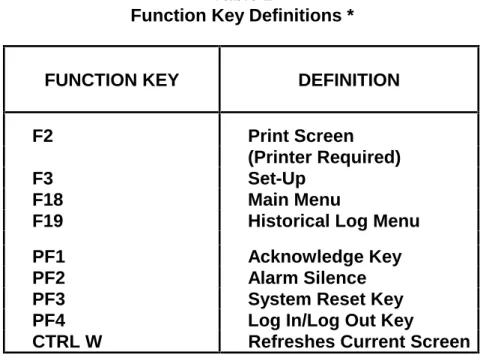
4.2.1 CRT Function Key Definitions
The Function Keys on the CRT keyboard are used to control the various system operations. Table 2 defines the various keys and their uses.
Table 2
Function Key Definitions *
FUNCTION KEY
DEFINITION
F2
Print Screen
(Printer Required)
F3
Set-Up
F18
Main Menu
F19
Historical Log Menu
PF1
Acknowledge Key
PF2
Alarm Silence
PF3
System Reset Key
PF4
Log In/Log Out Key
CTRL W
Refreshes Current Screen
4.2.2 Set-Up Procedure
The CRT must be set up[ correctly in order to receive and transmit data. An operator may enter the set-up mode to verify proper configuration. However, set-up procedures are performed by Simplex personnel and should not normally be performed by operators. (See publication FA4-11-224 for CRT set-up parameters.)
4.3
CRT SCREEN DISPLAYS
A variety of CRT screen displays are used to support system operations. Header information is displayed on the first three lines of the screen. The first line shows the time
These screens tell you what to do and when to do it. CRT screen displays are shown in Figures 6 through 10.
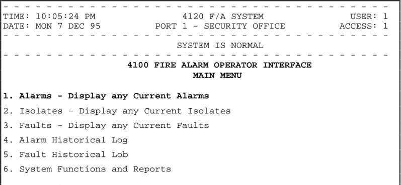
4.3.1 CRT Main Menu Screen
The CRT Main Menu Screen (Figure 6) is the first screen to appear after power is applied to the system. From the Main Menu Screen, you can display various system information screens. Items 1 through 6 are the available choices within this menu. View any item by either moving the cursor to the selection or by typing the item number and then pressing the <Enter> Key.
Figure 6 shows the cursor positioned on Item 1. To select Item 4 (Alarm Historical Log), move the cursor to Item 4 with the cursor control keys, or type the number <4> key and press the <Enter> key.
-TIME: 10:05:24 PM 4120 F/A SYSTEM USER: 1
DATE: MON 7 DEC 95 PORT 1 - SECURITY OFFICE ACCESS: 1
SYSTEM IS NORMAL
4100 FIRE ALARM OPERATOR INTERFACE
MAIN MENU
1. Alarms - Display any Current Alarms
2. Isolates - Display any Current Isolates
3. Faults - Display any Current Faults
4. Alarm Historical Log
5. Fault Historical Lob
6. System Functions and Reports
Select Option or PF1 to Acknowledge > 1
Figure 6
CRT Main Menu Screen
4.3.2 Acknowledge Screen
The entire system is configured as either a Global Acknowledge system or as an Individual Acknowledge system. If the system is configured as a Global Acknowledge system, two presses of the <PF1> key will acknowledge all abnormal conditions that can be annunciated by the port. When the system is configured as an Individual Acknowledge system, the Acknowledge key, <PF1>, must be pressed to acknowledge each condition change.
All conditions which can be displayed at the CRT can be acknowledged at the CRT, provided that the user has logged in at a sufficient access level. A tone on the CRT sounds to indicate unacknowledged conditions. (The tone can be silenced with the <PF1> key.) When an abnormal condition occurs, the user must select the appropriate acknowledge screen. The Header information on the screen indicates the number of abnormal conditions which can be annunciated by the CRT, and not necessarily the total number of abnormal conditions in the system. To acknowledge an abnormal condition, press the <PF1> key while in the acknowledge screen. The displayed condition will stop flashing, but will still indicate the abnormal condition. When all abnormal conditions have been acknowledged, the user can return to the Main Menu by pressing the <F18> key.
As with the operator information, alarms have priority over isolates and fault conditions. Multiple conditions are displayed in chronological order. Should multiple unacknowledged conditions occur, no unacknowledged event is allowed to scroll off the screen. If more unacknowledged conditions exist in the system than can fit on the screen, the :oldest” unacknowledged point is displayed first. After that condition is acknowledged, it scrolls off the top of the screen and is replaced by the next oldest condition.
The acknowledge screens are dynamic, and information is updated once per second. Follow the prompts at the bottom of the screen (shown in Figure 7) to silence signals (<PF2> key), or to reset the system (<PF3> key). When the system has reset, press the <PF1> key to acknowledge the condition change.
-TIME: 10:18:15 PM 4120 F/A SYSTEM USER: 1
DATE: MON 7 DEC 95 PORT 1 - SECURITY OFFICE ACCESS: 1
ALARMS=1 ISOLATES=0 FAULTS=0
-10:09:27 pm MON 7 DEC 95 SECOND FLOOR, EAST WING, ROOM 14
MANUAL CALL POINT ALARM
PF1=ACK, PF2=Silence, PF3=System Reset, PF4=Login, F18=Main Menu
Figure 7
CRT Acknowledge Screen
4.3.3 Log In Screen
It may be necessary to increase your CRT/Keyboard access level in order to acknowledge an abnormal condition. With the Main Menu displayed on the CRT screen, press the <PF4> key. A prompt will appear on the screen to “Enter your passcode”. (See Figure 8.)
Up to 19 passcodes are available to support user requirements. The passcode, in conjunction with the access level entered, determines if the operator can perform the required system functions.
-TIME: 10:06:31 PM 4120 F/A SYSTEM USER: 1
DATE: MON 7 DEC 95 PORT 1 - SECURITY OFFICE ACCESS: 1
SYSTEM IS NORMAL
4100 FIRE ALARM OPERATOR INTERFACE
MAIN MENU
1. Alarms - Display any Current Alarms
2. Isolates - Display any Current Isolates
3. Faults - Display any Current Faults
4. Alarm Historical Log
5. Fault Historical Lob
6. System Functions and Reports
Enter your passcode or ENTER to log out> XXX
Figure 8
CRT Log In Screen
4.3.4 Historical Log Screen
The Historical Logs are formatted differently from the CRT Acknowledge Screens. As on the operator interface panel, the Historical Logs are displayed with any entry number, followed by a time tag and the actual event.
The Historical Log shows all events in the system log, not just those events annunciated on the CRT. These screens are not dynamic. They display only historical data.
The view the Historical Log Screens, you must select the type of historical log from the CRT Main Menu Screen (Figure 8). These options are the Alarm Historical Log and the Fault Historical Log. Select the desired function either buy placing the screen cursor on the function name, or by pressing either the <4> key or the <5> key. Then, press the <Enter> key. A typical ALARM Historical Log is shown in Figure 9.
-TIME: 10:18:15 PM 4120 F/A SYSTEM USER: 1
DATE: MON 7 DEC 95 PORT 1 - SECURITY OFFICE ACCESS: 1
ALARMS=4 ISOLATES=0 FAULTS=0
-ENTRY 1 10:09:27 pm MON 7 DEC 95 SECOND FLOOR, EAST WING, ROOM 14
MANUAL CALL POINT ALARM
ENTRY 2 10:11:15 pm MON 7 DEC 95 SECOND FLOOR, EAST WING, ROOM 12
MONITOR ZONE ALARM
ENTRY 3 10:12:23 pm MON 7 DEC 95 SECOND FLOOR, EAST WING, HALL
MONITOR ZONE ALARM
ENTRY 4 10:13:45 pm MON 7 DEC 95 SECOND FLOOR, EAST WING, ROOM 15
MONITOR ZONE ALARM
F18=Main Menu, F19=Log Menu
Figure 9
CRT Alarm Historical Log Screen
4.3.5 Status Screen
When Menu Option 1, 2 or 3 is selected, the screen displays current abnormal screen conditions. The data displayed is updated once every second. The time and date information indicates when the point status changed from normal to abnormal condition. The screen format is the same as the format for the Acknowledge Screens. Flashing entries indicate unacknowledged entries. Figure 10 shows the CRT Status Screen displaying the Current Fault List.
-TIME: 11:15:11 PM 4120 F/A SYSTEM USER: 1
DATE: MON 7 DEC 95 PORT 1 - SECURITY OFFICE ACCESS: 1
ALARMS=0 ISOLATES=0 FAULTS=4
-10:19:29 pm MON 7 DEC 95 SECOND FLOOR, EAST WING, ROOM 14
SIGNAL CIRCUIT OPEN CIRCUIT FAULT
10:21:06 pm MON 7 DEC 95 MASTER BATTERY BACKUP
BATTERY STATUS IS FAULT
10:27:09 pm MON 7 DEC 95 SYSTEM/TIME INVALID OR NOT SET
FAULT POINT ABNORMAL
10:51:00 pm MON 7 DEC 95 SECOND FLOOR, EAST WING, ROOM 15
FIRE MONITOR ZONE ISOLATE FAULT
PF1=ACK, PF2=Silence, PF3=System Reset, PF4=Login, F18=Main Menu
4.4
THE SYSTEM PRINTER
The system uses a printer to provide a hard copy of the system’s current status. The system supports both DC and AC printers.
A DC printer printline is 40 characters long. A typical DC printer printout is shown in Figure 11.
10:09:27 pm MON 7 DEC 95
2ND FLOOR EAST WING, ROOM 14
MANUAL CALL POINT ALARM
10:10:36 pm MON 7 DEC 95
ALARM ACKNOWLEDGED AT MAIN PANEL
10:15:12 pm MON 7 DEC 95
ALARM SILENCE IN PROGRESS
10:16:09 pm MON 7 DEC 95
SIGNALS SILENCED AT MAIN PANEL
10:17:10 pm MON 7 DEC 95
SYSTEM RESET IN PROGRESS AT MAIN PANEL
10:19:12 pm MON 7 DEC 95
SYSTEM RESET IN PROGRESS
10:19:33 pm MON 7 DEC 95
2ND FLOOR EAST WING, ROOM 14
MANUAL CALL POINT NORMAL
10:19:45 pm MON 7 DEC 95
2ND FLOOR EAST WING, ROOM 14
NO ALARMS PRESENT, SYSTEM RESET COMPLETE
Figure 11
40 Character Line Width Printout
The AC printer prints only in black, with line widths of 80 characters. A typical AC printer is shown in Figure 12.