Structural Engineering Responsibilities and Structural Components: A Premanufactured Wood Truss Case Study
Stewart M. Verhulst, M.S., P.E., M.ASCE1 Deepak Ahuja, M.S., P.E., M.ASCE2
1
Nelson Architectural Engineers, Inc., 9701 Brodie Lane, Suite 201, Austin, Texas 78748; PH (512) 610-2800; email: [email protected]
2
Nelson Architectural Engineers, Inc., 2470 Dallas Parkway, Suite 220, Plano, Texas 75093; PH (469) 429-9000; email: [email protected]
ABSTRACT
Structural Engineers have a duty to their clients and the public to provide safe designs. Typically, the Structural Engineer of Record is responsible for the structural design of the overall project, including specification of the design loads, issuance of design documents, and review of submittals.
When structural components are used, the engineer for the Component Designer/Manufacturer is responsible for the design of individual structural components. This can constitute a significant portion of the structural design on ae project. Structural Engineers must understand their duties and must also be aware of the extent to which structural component design is (or is not) being performed by a Professional Engineer.
In the subject case study, the Component Designer/Manufacturer's licensed engineer was not familiar with the project layout and only reviewed the design output for the individual components, without regard for the framing layout and the resulting loading conditions. As a result, the project was built with structural inadequacies, which necessitated extensive repairs.
INTRODUCTION
General. In the building industry, Structural Engineers have a duty to their clients to provide proper and safe designs and a duty to ensure public safety in their designs. The Structural Engineer typically fulfills these duties by directly supervising the design work, as designated by issuance of sealed documents and by reviewing submittals and shop drawings for the structural members and materials used for construction. For premanufactured wood trusses discussed in this case study, the Component Designer/Manufacturer is also typically required to provide sealed documents. The Component Designer/Manufacturer in this case study created the layout scheme for many of the primary framing components. The study outlined herein shows the effect of significant structural design being performed by a Truss Designer/Manufacturer without the oversight of a licensed Structural Engineer.
Structural Engineers must understand their duties and be aware of the extent to which framing component design is (or is not) being performed by a licensed engineer. Structural components. Structural components are commonly used in buildings with highly repetitive structural loading conditions. For instance, warehouse buildings typically have structural components such as steel joists for roof framing. For this type of component design in simple structures, component manufacturers often provide tables and charts as design aides to the engineer.
Component design for more complex structures is somewhat different. If the loading conditions for the components vary and are not repetitive, it is necessary to determine the loading for each component and then design the component to meet the loading requirements. Engineering work is required to determine the correct load magnitudes and loading conditions for each component.
The manufacture of many types of structural components, including metal plate connected wood trusses, is a volume business. With many different manufacturers making basically the same type of product, there are competitive market pressures, dictating tighter profit margins. There are economies of scale involved. There are project schedules to meet. This is not to say that quality is not a concern of the component manufacturers; it is just a fact that quantity and speed are deciding factors to success in the marketplace.
CASE STUDY
Overview. This case study considers a condominium project located in Dallas, Texas. The project included three (3) buildings of similar construction. There were a total of 17 condominium units, but there were only four (4) distinct unit floor plan layouts. Therefore, the unit layouts were repeated in the three (3) buildings. The condominium buildings were three-story buildings (plus an attic) and were built in 2000-2001.
The condominium buildings were wood-framed structures. The 1st floor was supported by a reinforced concrete slab-on-grade foundation with piers. The framing at the 2nd and 3rd floors consisted of metal plate connected wood trusses and engineered wood beams - both glued laminated (glulam) beams and parallel strand lumber (PSL) beams. The vertical support consisted of wood stud walls, with groups of studs serving as columns for concentrated loads. The interior finishes were typical for residential construction in the area, including wood floors, carpet, and gypsum board walls and ceilings. In addition to the floor loads, there was some brick veneer supported by the framing (i.e., not continuously supported to the foundation), and there were balconies off the attic areas, at the highest level of the units.
The authors were retained to investigate the complaints of the unit owners, which included deflections and uneven floors and ceilings. Specifically, the structural design was evaluated to determine if structural deficiencies were contributing to the deflections and to the floor levelness issues.
The authors' investigation began less than three (3) years after the construction of the condominiums was completed. The unit owners had several complaints, including but not limited to: uneven floors, sloping countertops, cracks in
finishes, separations in wood flooring, cracks in brick veneer, and sticking and swinging doors. Although the investigation encompassed several issues and causes of distress, this discussion is limited to the issues related to the design of the floor framing.
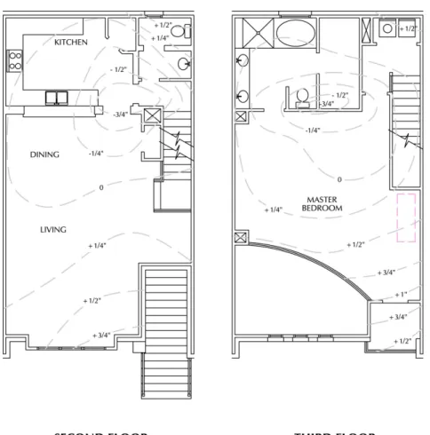
A floor elevation survey was performed for each unit type to determine the extent and pattern of floor unlevelness for each framing layout. Based on these elevation surveys and the visible distress, a pattern of deflection was observed at some of the interior walls and framing support locations. The surveys also ruled out foundation movement as a cause of unlevelness at the 2nd and 3rd floors. Refer to Figure 1 for the relative elevations at the 2nd and 3rd floors of one of the units.
Figure 1. Elevation surveys at 2nd and 3rd floors of one condominium unit. The lowest elevations occur below a non load-bearing wall at each floor.
The overall patterns of floor unlevelness indicated that there were load transfer deficiencies at the floor framing. For the unit depicted in Figure 1, the exterior walls were load-bearing and all of the interior walls, except for the stairway wall, were not intended to be load-bearing. Also, as indicated in Figure 1, the lowest points at the 2nd floor and 3rd floor occurred where the truss framing was supported on walls that were not intended to be load-bearing. These non load-bearing walls were not continuously supported to the foundation.
Structural design. The structural design for the project was performed by a combination of the Structural Engineer of Record and the Truss Designer/Manufacturer. The Structural Engineer of Record was responsible for the overall structural design, including the foundation and lateral load resisting systems. The Truss Designer/Manufacturer was responsible for the design of the metal plate connected wood trusses.
The Structural Engineer of Record prepared the original structural framing layout schematic. However, the Truss Designer/Manufacturer prepared a different layout scheme for the truss and beam framing at the floors. This revised layout scheme was customized for the design of the trusses and beams and was adopted for construction.
The Truss Designer/Manufacturer designed the trusses and produced floor framing layout drawings (the "Truss Placement Plans") along with individual drawings for each of the trusses. The individual truss "cut sheet" drawings (the combination of the layout drawing and individual truss drawings is referred to as the "shop drawings" herein) were signed and sealed by a licensed Professional Engineer, an employee of the Truss Designer/Manufacturer.
Loads and load transfer issues. The Structural Engineer of Record provided the loads to be used for the truss design. These loads included a typical dead load of 20 psf (0.96kPa) and a floor live load of 40 psf (1.92 kPa) at the living spaces (increased to 60 psf (2.88 kPa) at the balconies). The Truss Designer/Manufacturer had to calculate the loads throughout the structure, taking into account special loads and all load transfer conditions. These calculations constituted a significant portion of the design of the truss framing and would have been required regardless of the framing layout.
Furthermore, some of the non load-bearing walls were included on the Truss Placement Plans and it was not clearly indicated which walls were load-bearing and which walls were not. Refer to Figure 2 below, which indicates the Truss Placement Plans for the 2nd floor of one of the unit types. At the very least, the truss shop drawing layout plan was confusing regarding the locations of the load-bearing walls. The result was that the Truss Placement Plans were confusing to the framer who erected the framing, and was even confusing to the Professional Engineer working for the Truss Designer/Manufacturer.
Based on the authors' review of the design documents and the measured floor elevations, the primary deflections and relative low points in the floors occurred at walls that were not designated as load-bearing, indicating load transfer from non load-bearing walls into the framing below (refer to Figure 1).
Some destructive testing was performed at the framing to observe the connections and the possibility of load transfer at the non load-bearing walls. Nearly all of the truss and beam framing was in contact with, and therefore was bearing on, the walls below (refer to Figure 3). This condition essentially made every wall a load-bearing wall.
Consequently, the load from these walls was transferred into the framing below. This framing was designed to support the weight of the wall only and was not designed to support loads transferred from above.
Figure 2. Example of the Truss Placement Plans. The wall below the mid-span of the trusses marked "F32" and "F33" was not intended as load-bearing, but
was included in the Placement Plans.
Figure 3. Truss bearing on a wall not designed as load-bearing. Note the nail connecting the truss to the wall (follow arrow).
In addition to the interior load transfer issues, it was also determined that some of the truss and beam framing was underdesigned. The magnitude and location of some of the loads used for the component design (by the Truss
Designer/Manufacturer) were incorrect, primarily due to incorrect calculations considering tributary areas and load transfers.
One area where unconservative loads were commonly used in the design was at the upper level concrete balconies. The design for the premanufactured trusses did not consider the proper dead load or live load for these balconies. Another area where the loading was incorrectly calculated occurred where wood framing was supporting brick veneer. Although brick veneer support is a safety issue unto itself, some of the brick load was supported by the truss framing. This brick load was not accounted for in the truss design.
The load transfer issues and the use of unconservative loads for component design resulted in undersized structural members and unsafe conditions. These conditions existed to some degree in each of the four (4) unit types, and all three (3) of the buildings were similarly affected.
The subject condominium structures were certainly not uniquely complex structures. However, because of the varying loading conditions and load transfer issues, they were not simple structures either. With 3-story framing plus an attic and roof, there were a variety of load transfer and support conditions requiring consideration (and calculation). Because the walls were not all "stacked" (they did not all line up from floor to floor), some of the floor framing trusses at the attic and 3rd floor were not bearing on walls that were continuous to the foundation. Also, because the structures had three (3) stories plus an attic and roof, the magnitudes of the structural loads caused increased demand on the structural framing compared to the typical one or two-story structures for which this type of wood framing is commonly utilized.
DISCUSSION
Standards of practice for engineering. The Component Designer/Manufacturer is required to perform structural engineering to determine the loading for each of the components, based on the design loads provided by the Structural Engineer of Record.
Each state has jurisdiction over the practice of engineering in that state. Therefore, each state has laws and rules for the practice of engineering, although these are generally similar from state to state. Generally, a Professional Engineer is required to directly perform or directly supervise all engineering work sealed by the engineer. As a point of reference, the State of Texas (Texas Board of Professional Engineers 2007) provides a definition of the practice of engineering, which includes: "design, conceptual design, or conceptual design coordination for engineering works, products or systems", and "development or optimization of plans and specifications for engineering works, products, or systems". Furthermore, the "direct supervision" required of an engineer for engineering work product is defined as follows:
The control over and detailed professional knowledge of the work prepared under the engineer's supervision. The degree of control should be such that the engineer personally makes engineering decisions or personally reviews and approves proposed decisions
prior to their implementation. The engineer must have control over the decisions either through physical presence or the use of
communications devices.
An independent licensed Professional Engineer (not directly employed or contracted by the manufacturer) cannot directly supervise the engineering work performed by a Component Designer/Manufacturer. Therefore, the Component Designer/Manufacturer is required to employ a licensed Professional Engineer to perform or directly supervise the engineering work for the component design. This ensures that all of the calculations for the structural design of a building are performed under the direct supervision of a licensed Professional Engineer.
If the above states the theory of what should be done, what is the reality? Are all calculations for component design performed under the direct supervision of a licensed Professional Engineer? While Structural Engineers of Record do have a duty to ensure public safety, they are not required to perform work outside their scope of service. Structural Engineers of Record are typically required to review shop drawings, such as those prepared by a Component Designer/Manufacturer, but they are not required to retrace all of the design calculations performed by the Component Designer/Manufacturer to determine if the components were designed correctly. The Structural Engineer of Record is required to review the shop drawings for conformance with his/her design, but this does not constitute a line-by-line verification of the engineering work performed by the Component Designer/Manufacturer.
The Truss Plate Institute (TPI) is an organization that creates standards for the wood truss industry in the USA. In the commentary for the National Design Standard for Wood Truss Construction (Truss Plate Institute 2003), TPI describes the duties of a Truss Designer as follows:
7.0 TRUSS DESIGNER RESPONSIBILITIES
7.1 The Truss Designer shall prepare the Truss Design Drawings
based on the truss design criteria and requirements set forth in writing by the Owner, Building Designer or Contractor, by the Building Structural System Design Documents, and in conformance with the requirements set forth in the Truss Design Standard.
While TPI does not discuss specific engineering responsibilities or protocol, the Truss Designer is performing engineering work, and is therefore required to conform to the standard of practice for engineering. As noted above, this includes direct supervision by a licensed Professional Engineer over all engineering work. Engineering roles. For the case study project, the Truss Designer/Manufacturer created the Truss Placement Plans, which indicated the floor framing layout for each of the units, and performed the design of the floor trusses. There was an engineering seal on the shop drawing for each truss on the project. The Truss Placement Plans, however, were not sealed.
Representatives of the Truss Designer/Manufacturer gave deposition testimony regarding the project, providing some insight into the design process and methods used. Based on this deposition testimony, the Professional Engineer who sealed the truss drawings, by his own admission, did not have any involvement in the calculation of the loads for the trusses. This work was performed by a "designer", an employee of the Truss Designer/Manufacturer who was not a Professional Engineer. The employee who designed the project was therefore not directly supervised by the Professional Engineer who sealed the truss drawings. This conduct is a violation of the standards of practice for engineering.
Deposition testimony further revealed that the Professional Engineer who sealed the truss drawings was not familiar with the architectural floor plans or structural drawings for the project, and was not even familiar with the Truss Placement Plans that accompanied the signed and sealed truss drawings. Furthermore, this Professional Engineer testified that it was not common practice for the engineer sealing the truss drawings to review the structural and architectural drawings.
In fact, while looking at the Truss Placement Plans for the project (prepared by his employer) during the deposition, this engineer incorrectly identified non load-bearing walls as load-load-bearing. The engineer stated that he was not familiar with the Truss Placement Plans and the framing layout. This admission indicated that the engineer was also not familiar with the loading conditions and the load path through the framing.
The question then becomes: If the Professional Engineer employed by the Truss Designer/Manufacturer is not responsible for this engineering work, who is responsible? The Structural Engineer of Record had the understanding that the Truss Designer/Manufacturer's Professional Engineer was responsible for the totality of the truss design, including the determination of individual truss loading and load paths. The Structural Engineer of Record must review the shop drawings and must also perform load calculations for other structural members and systems. However, the Structural Engineer of Record cannot have direct supervision over engineering decisions that are made and implemented by representatives of the Truss Designer/Manufacturer. In this scenario, the Truss Designer/Manufacturer had the responsibility to provide supervision by a licensed and qualified Professional Engineer over their engineering work. For this case study, this was not done in accordance with the requirements of the standard of practice for engineering.
While there were shortcomings in the shop drawing review by the Structural Engineer of Record, some of the design errors made by the Truss Designer/Manufacturer may have not been caught even with a thorough review of the shop drawings. Shop drawing review is one "line of defense" to detect design errors, but it cannot be used as a crutch by those preparing the shop drawings.
It was further discovered that the "designer" and the Professional Engineer for the Truss Designer/Manufacturer had as many as fifty (50) projects ongoing at the time and that this was a typical workload. This indicates a significant volume of engineering work for one Professional Engineer. The case study project included 118 different trusses plus some channel frames. The Truss Designer/Manufacturer's Professional Engineer estimated that it would take 1 1/2 hours to review the drawings
and calculations for a project of this size. This time estimate equates to less than 1 minute per truss and is not nearly enough time to perform an adequate review of the engineering work. Also, this review does not comply with the previously noted requirements for direct supervision, as the Professional Engineer did not have control over the project and did not make or approve many of the engineering decisions.
Because the engineering design of structural components was not performed under the direct supervision of a Professional Engineer, the Component Designer/Manufacturer did not comply with the duties of the engineering profession and there is an increased likelihood of structural deficiencies. This is an important issue, as unsupervised engineering work can result in an increased danger to the public.
SUMMARY
The case study discussed herein illustrates a situation where a Component Designer/Manufacturer performed significant engineering work on a building design. A substantial portion of this engineering work was not performed under the direct supervision of a licensed Professional Engineer.
While the Structural Engineer of Record is responsible for the overall structural design on a project, it is not in his/her scope of work to perform an exhaustive review of the calculations and design work performed by a Component Designer/Manufacturer. Structural Engineers must be aware of their scope of work as it pertains to structural components. Structural Engineers should delineate what work they are responsible for and what work is the responsibility of others. The Structural Engineer of Record for the project highlighted in this case study did approve the shop drawings, but he did not perform an exhaustive calculation review, nor was he required to do so.
An unlicensed individual performed critical engineering work, without direct supervision by a licensed Professional Engineer. Due to this lack of proper supervision over the design, structural deficiencies in the design were not identified prior to the completion of construction. As a result, extensive repairs were required to the structural framing after the construction was completed and the individual homeowners had occupied the buildings, creating inconvenience and significantly increasing the cost of the repairs.
Considering the engineering design of structural components, the ultimate responsibility resides with the Component Designer/Manufacturer. It is not acceptable for these components to be designed by unlicensed individuals without direct supervision by a licensed Professional Engineer. The authors acknowledge that component design and manufacture is often a volume business, requiring repetitive designs with quick turnaround times. However, for more complex projects, such as multi-story structures with load transfers, structural engineering work cannot be adequately performed under these conditions. The Component Designer/Manufacturer must provide proper supervision by licensed Professional Engineers over their engineering work.
Even though it is the duty of the Component Designer/Manufacturer to perform the design work for these components, the Structural Engineer of Record
should perform a thorough review (not an exhaustive review or re-doing of the work) of the shop drawings, with special consideration for unique structural complexities such as load transfers. This review may uncover mistakes that indicate a lack of supervision by the Component Designer/Manufacturer.
While the authors realize that it is already accepted practice for Structural Engineers of Record to review shop drawings, our goal is to highlight that Structural Engineers should be aware of what work is (and what work is not) being performed under the direct supervision of a licensed Professional Engineer working for the Component Designer/Manufacturer.
We recommend that Component Designers/Manufacturers ensure that their design processes comply with the standard of practice for engineering, including direct supervision over all engineering design by a licensed Professional Engineer. We further recommend that, as a part of their shop drawing review for structural components, Structural Engineers of Record attempt to better understand whether or not all of the engineering work has been performed with the proper amount and quality of supervision.
The authors' concern is that it is generally accepted by Structural Engineers that component design, including the distribution of loads to individual members, is being performed under the direct supervision of licensed Professional Engineers. Based on this case study, this is not necessarily true in every case. Component Designers/Manufacturers must provide direct engineering supervision over their engineering designs, and Structural Engineers are advised to understand and verify the extent to which a Component Designer/Manufacturer has provided this direct engineering supervision. When Component Designers/Manufacturers are performing engineering design, they must comply with the standard of care for licensed Professional Engineers.
REFERENCES
Structural Engineers Association of Texas (SEAoT). (1998). Guideline for Practice, Second Printing.
Texas Board of Professional Engineers. (2008). Texas Engineering Practice Act and
Rules Concerning the Practice of Engineering and Professional Engineering,
Texas Board of Professional Engineers, Austin, TX, p.36.
Truss Plate Institute (TPI). (2003). National Design Standard for Metal Plate
Connected Wood Truss Construction, TPI, Madison, WI, p.77.
Wood Truss Council of America (WTCA). (2002). Metal Plate Connected Wood