Machining
Important regulations and information
NAME WHO'S AFFECTED
Health & Safety at Work Act etc. 1974 (HASAWA)
Everyone at work and customers exposed
to risk from faulty products.
Noise at Work Regulations Anyone exposed to noise of 85dB(A) or
above and those assessing noise levels.
Personal Protective Equipment Regulations
Anyone who needs protection to; sight, hearing,
lungs, hands, legs, feet, head & body. Power Press Regulations People using & maintaining power
presses. Provision & Use of Work Equipment
Regulations
Affects users of any equipment. 1998 (PUWER 98)
Control of Substances Hazardous to Health
Everyone. (COSHH)
Signs and labels
There are hazard signs and labels that you could come across in the workshop. Labels on containers are orange, signs on walls are yellow.
Task 1 - On the back of this sheet draw the signs for Harmful and Toxic Task 2 - What words appear on the warning sign with a fire symbol on it? _________
Who is the first aider in your workshop? _______________
If you had an accident who should would you tell first? ________________
You have duties under the Health and Safety at Work Act etc. 1974 (HASAWA) - write down the Employees Duties under this act. You will find them on the Health and Safety Notice: 1.__________________________________________________________
2.__________________________________________________________ 3.__________________________________________________________ 4.__________________________________________________________
There may be other rules that apply to your own workshop. Write them down here: 1.__________________________________________________________
2.__________________________________________________________ 3.__________________________________________________________ 4.__________________________________________________________
Drawings and work instructions
Before starting a job, make sure you can read, interpret and understand:
any safety instructions
job instructions
engineering drawings
quality control documents.
Always check you have the correct drawing number and issue.
What information do you usually need when given a machining job to do? __________________________________________________________ __________________________________________________________ Where is the information kept?
__________________________________________________________ What procedures are used in your workplace for storing information safely? __________________________________________________________ How should you take care of drawings?
__________________________________________________________ __________________________________________________________ How do you find out if a drawing is the latest issue?
__________________________________________________________ __________________________________________________________
Planning the job
Procedure:
check you have the right drawing number and it is the right issue
read the drawing thoroughly, every line, dimension, tolerance, material specification and note.
Then choose:
the machining method
the machine
the tools
the operation sequence together with the workholding methods and make up a planning sheet.
Now find out:
the materials needed
the consumables required
the quality checks required and if reworking the component is allowable if needed.
Next, obtain:
the workholding devices
the cutting tools
the measuring equipment
and check all these for fitness for purpose.
Now show your planning sheet to your supervisor, to make sure all the relevant machining operations are covered.
Here is an example of a planning sheet:
Job No Drawing No Title Material
T1 TRG 01456 Iss 3 Stepped Bush BMS
Op No Operation Tool/Equipment Remarks Tol
1 Chuck material 3 jaw chuck
2 face off bar facing tool
3 Drill centre No 3 centre drill
4 Centre revolving centre
5 Rough turn 25mm dia 45 rougher 102mm long +/- 1mm 6 Rough turn 19mm dia R/H knife tool 58mrn long +/- 0.5mm 7 Finish turn 25mm dia straight round nose 100mm long +/- 1mm 8 Finish turn 19mm dia R/H knife tool 60mm long +/- 0.1mm 9 Check dias and lengths micrometer/vernier check
calibration calliper dates 10 Part off to size parting off tool
Good housekeeping
A good way to manage the working area is to apply the 58's. This is a Japanese system that can be applied to any-work place:
sort it out - go through the area and remove any unwanted items
shine it up - clean the machine thoroughly, get all the swarf out, clean the area
around the machine
store it - find a place for everything and keep it there, look after your tools, safety
specs etc.
set limits - don't borrow or lend tools + help the team you work with by doing it
right
self discipline - once you have done it and made an improvement, keep it up.
You will save a lot of time and effort and have a better environment. Work smarter not harder!
Remember:
leave the machine in a safe condition (i.e. isolated, cutting tools removed, clean)
dispose of waste materials correctly
return tools, equipment and surplus materials to stores
label and record completed workpieces
protect workpieces from damage/corrosion if required.
What are the procedures for good housekeeping in your work area?
____________________________________________________________ ____________________________________________________________ ____________________________________________________________ ____________________________________________________________ ____________________________________________________________ ____________________________________________________________ ____________________________________________________________ ____________________________________________________________ ____________________________________________________________ ____________________________________________________________ ____________________________________________________________ ____________________________________________________________
Specific safety precautions Main hazards when turning:
Hazard What to do
Electrical:
• faulty/damaged cables Inspect and report • damaged switches Inspect and report • emergency stop buttons not
operational Report, do not use
• coolant in contact with live parts Do not switch on, report. Physical:
• guards missing, damaged or loose Inspect and fix or report • rotating parts Ensure guards in place
• rings, jewellery, ties etc. Remove these items when operating lathes
• long hair Tie it back and/or wear a hat
• parts flying off Double check all settings, especially when
using a faceplate or turning between centres.
Chemical:
• coolants in contact with skin Use barrier cream at all times • dust and fumes when machining Always use extraction system.
Parts of a lathe
No Name Function
1 Headstock and spindle Contains gears and drive for rotating the work 2 Machine bed Main frame for holding saddle and tailstock 3 Tailstock To hold drill chuck or supporting centre 3a Tailstock handwheel To adjust position of centre, or to feed the drill
chuck
3b Locking lever Locks tailstock into position
4 Saddle, cross slide and Positions the tool relative to the work. Provides tool
compound slide movement axially, radially, and at an angle. 4a Saddle locking clamp Clamps the saddle to the bed when the cross
slide is in use
5 Main switch or isolator Switches machine on and off 6 Starting lever Starts the spindle
7 Motor reversing switch Reverses the direction of the spindle 8 Speed selector Changes speed of spindle
9 Spindle nose Mounting point for chucks, faceplate or driving plate
10 Feed selectors Selects feed rate of tool 11 Emergency stop Stops the machine
Work holding devices Helpful tips
1. To protect finished diameters use a brass or aluminium shim under each jaw. This will prevent the jaws marking the work.
2. Position a stop on machine bed to prevent running into chuck with tool.
Changing the jaws:
isolate machine
wind jaws all the way out
look for the numbers stamped on them and take out in reverse order, 3 - 2 - 1
clean and oil jaws and store them.
1 Three jaw chucks
The three jaw chuck is the most useful work holding device for the lathe. It is self centring and can be fitted with a variety of different jaws. Inside and outside
diameters can be held.
Workpieces can be round or hexagonal but not square or odd shaped.
Safety warning - The chuck key must be in one of two places, in your hand or on the bench. Never out of your hand and in the chuck.
Replacing jaws:
clean all parts of chuck
ensure new jaws are clean
rotate chuck key until edge of scroll is just clear of slot 1
place jaw 1 in slot 1
turn key until it is gripped
repeat for jaws 2 & 3.
Clamping on external diameter:
isolate machine
open chuck jaws
place workpiece in jaws with minimum amount protruding to allow for machining
tighten chuck
rotate to check for concentricity.
2. Four jaw chucks
The difference between 3 and 4 jaw chucks is that the 4 jaw chuck has no scroll plate. The jaws are able to move individually. This allows a wide variety of shapes to be held.
Clamping round workpieces:
isolate machine
use rings on chuck face as a rough guide
adjust jaws to hold workpiece as central as you can by eye
rotate chuck and continue adjusting until workpiece runs true.
Centring work with dial test indicator:
set DTI up on compound slide or in tool post
rotate chuck until indicator reads highest point
rotate chuck to opposite jaw
slacken this jaw slightly, about Y2 the difference.
Go back to the opposite jaw and tighten it. Repeat the operation until the pointer does not move or the movement is within the allowable limit of run-out.
Safety warning - it is tempting to leave chuck
jaws slack when a good reading has been obtained. Always go round all jaws and check that they are tight. This may
mean some more adjustment is needed.
Collets
Collets are used to hold work accurately, especially where batches of small parts are produced from rods of material. The collet system consists of the collet and a draw bar, which goes in through the back of the spindle. When screwed up the taper on the collet forces the splits to close and grip the rod.
Note:
collets are available in metric or inch versions
small increments of size are catered for - use the next one up from work size to reduce strain on the collet
never use a smaller collet than the diameter of the work. The collet will be damaged
never have long rods sticking out beyond the rear of the lathe unless special rod supports are used
a range of shapes can be catered for, collets with hexagonal or square bores are available.
Turning between centres
You need:
dead centre for headstock, driving plate, carrier
Live centre for tailstock.
Having centre drilled work, fit carrier on to it:
fit dead centre into headstock, driving plate in place of chuck and live centre into tailstock
fit workpiece between centres
Set tailstock so there is no play but workpiece rotates freely.
Safety warning - when turning between centres always take light cuts and recheck
all settings after first cut. Heavy cuts or work becoming loose can cause tool to dig in and work to be ejected from the lathe.
Cutting tools
Types of cutting tools
There are two main types, High Speed Steel (HSS) and Tungsten Carbide:
• High Speed Steel (HSS)
An alloy steel produced as rectangular section blanks to grind to specification or as tips welded to a mild steel shank and pre-shaped ready for use.
Properties:
Good wear resistance allows reasonably high cutting speeds.
easily shaped and reground on standard type grinding wheels
not suitable for high production rates
Can give excellent surface finishes.
• Tungsten carbide
Not a metal but 'sintered' - produced from tungsten carbide powder under great heat and pressure. Supplied as either tips brazed onto a mild steel shank or as inserts which are fixed into a specially designed holder and as each face wears tips can be turned to expose a new face. Tungsten carbide comes in a wide variety of grades, manufacturers supply booklets with tables showing which grade is suitable for the work you are doing.
Properties:
extremely hard material, very high cutting rates can be achieved
brazed variety can be reground using a special 'Green Grit' wheel and finished on a diamond wheel
inserts may have a coating of a ceramic which increases cutting rates further, but these are meant to be thrown away once all faces are worn
suitable for high production rates
Doesn’t stand up well to shock loads- may chip or shatter under the shock of intermittent cutting, e.g. when turning workpieces with grooves or odd shaped sections.
Typical lathe tool shapes
Tool rake and clearance angles
Successful and accurate machining can only be accomplished by the use of correct cutting tools, ground to the most suitable angles for the material being used and machined in a correct manner. The rake and clearance angles listed in the chart below are applicable to varying materials to be machined.
It will be noted from the chart that the top rake angle varies the least and should be no more than necessary.
If excessive clearance is allowed, the point of the tool becomes too sharp, losing its necessary strength and heat dissipating area.
More clearance is often required, however, for boring tools.
Roughing and finishing
Roughing cuts are taken to remove large amounts of material quickly. Speeds are generally lower and feeds tend to be coarser than those used for finishing.
Roughing tools are designed for strength, as they need to stand up to heavy cuts. Finishing cuts are taken to achieve the required accuracy and surface finish. Feed rates are lower to achieve good surface finishes. Always take a definite cut - if you let the tool rub the tool will wear, the metal surface will glaze over and the next cut will then take too much off. This glazing is called burnishing.
Stress relief
When metal. is produced it is hot or cold 'worked' by rolling. This process is carried out to achieve the required structure and dimensions. However, it can leave
unwanted stresses in the material. When you cut through the outer skin these stresses can be released, which can produce distortion. Round sections can become oval and rectangular sections can bend.
Material Front Front Side Side
(or top) clearance rake clearance
rake (A) (8) (C) (0) Soft steels 15° 8° 15-20° 6° Medium steels 8-10° 8° 12-15° 6° Hard steels 5° 6° 6-10° 6° Cast iron 8° 8° 10-15° 6° Brass and Bronze 1° 6° 0-3° 6° Copper 20-25° 10-15° 20-30° 2-5° Aluminium 35-55° 6° 10-20° 1-3° Plastics 0-2° 6° 0-3° 6°
Setting speeds, feeds and depth of cut The usual sequence is:
choose (or look up) the cutting speed
calculate the spindle speed
calculate (or choose) the feed rate
choose the depth of cut, depending on the power and condition of the machine.
The cutting speed is:
one that has been found by experiment to work best for a particular combination of tool material and workpiece material
usually looked up in tool manufacturers reference booklets
expressed in metres per minute.
Here are some examples, but remember that any figures you are given should always be a starting point - start at the lowest speed given.
Material Tool type Cutting speed
(metres/minute)
Grey cast HSS 25-30
iron Tungsten carbide
tipped 75-100
Free cutting HSS 40-50
mild steel Tungsten carbide
tipped 140-150 Brass HSS 70-80 Tungsten carbide tipped 150-160 Aluminium HSS 180-200 Tungsten carbide tipped 360-400
The spindle speed is:
the rate at which the spindle rotates
expressed in revolutions per minute, RPM. To work out spindle speed in RPM the formula is: Revs per minute = 1000 x Cutting speed (metres/ min) 3.14 x Diameter of work (millimetres)
Then set the machine to the nearest lower speed available.
The feed rate is:
the rate at which the tool advances into the workpiece
expressed as millimetres per minute (milling machines) or millimetres per revolution (lathes).
The feed rate:
can be chosen from the chart on the head stock
is set by adjusting the appropriate levers. Coarse feed rate for roughing is about 0.5 mm/rev.
Fine feed rate for finishing is about 0.04 mm/rev.
Here are some examples using figures from the table: diameter of work - 25mm material - mild steel
cutting tool - HSS cutting speed - 40 m/min so RPM = 1000 x 40
3.14 x 25 = 40000 78.5
=509 RPM (approx. 500 RPM)
Suppose the material is changed to aluminium: diameter of work - 25mm material - aluminium
cutting tool - HSS cutting speed - 180 m/min so RPM = 1000 80 3.14 x 25 = 180000 78.5 = 2292 RPM (approx. 2300 RPM)
Exercise 1 Work out the speed for drilling aluminium. Insert the missing values in
the boxes in the formula given below:
diameter of drill material drill cutting speed so rpm = [ ]x[ ] [ ]x[ ] = [ ] [ ] = [ ] rpm (approx. [ ] rpm).
Exercise 2 Calculate the speed for turning steel, using a tungsten carbide tool
diameter of work - 25mm material - mild steel
cutting tool - tungsten carbide cutting speed - 140 m/min so RPM = [ ] x [ ] [ ] x [ ] = [ ]
[ ]
Using dials and readouts Dials
Dials measure the movement of the slide or table. They may be marked in:
inches and thousandths of an inch (0.001"). One turn would typically be 0.125"
metric and marked in mm. Typically 0.02mm is the smallest division and one turn represents 3mm.
There are metric/inch dials fitted to some machines. This type has two rings which are mechanically geared to move at different speeds.
Backlash
Dials measure the angular position of the leadscrew, which relates to the actual slide or table position. Backlash is the slack between the leadscrew and the nut. You can measure it by:
moving the slide and locking it, then turning the dial back.
It will move freely for part of a turn- that is the backlash. It could be as much as 1 mm on a well-used machine.
The problem with backlash on a machine tool slide is that immediately you change direction you get a false reading - by the amount of backlash present, because the dial moves but the slide does not.
This can be avoided by always moving the table in the same direction as you are machining. If you reverse direction the effect will be to produce an error equal to the backlash.
Digital read-outs
These units are added on to a machine and consist of two sender units which can measure the position of the table in the X and Y directions. Signals are sent to a display unit which has 2 rows of LED characters which give the operator the position of the table.
The main advantages of digital readout systems are:
the table position is measured, not the position of the lead screw so that backlash error is eliminated
a measurement can be pre-set (e.g. if you are using a 4mm diameter edge finder, you can set the reading at -2.00mm which means that when the display reads 0.00mm the centre of the cutter is exactly over the datum edge)
instant conversion from metric to imperial units at the touch of a button
resolution is usually higher. As digital readouts normally work to smaller units than the machine dials, you don't have to resort to splitting marks on a dial in order to achieve the required accuracy.
Turning operations Centre drills
Centre drills come in HSS or carbide versions. Both are very hard and brittle. When feeding in take care, have plenty of coolant and withdraw frequently to avoid chips jamming in the flutes.
Drills
Drilling on the lathe is similar to any other type of drilling, and drills can break if the chip builds up and jams the drill. To overcome this problem:
ensure that the coolant is directed right into the hole
frequently withdraw the drill all the way out to clear it. Drills are supplied in:
HSS
solid tungsten carbide
inserted tooth forms.
Reaming
Reamers are used to remove small amounts of metal from holes, giving greater accuracy and improved surface finish than drills. When reaming:
keep a steady feed rate
withdraw the reamer when resistance is felt
clear the hole of swarf
wind the reamer in again.
Use a slower speed and a faster feed rate than for drilling.
Boring
The single point boring tool allows you to:
produce accurate holes to any size
get good surface finishes. As you can't see what is going on, you have to listen and feel - the cutter will tell you when
something is wrong. Boring tools are normally weaker than turning tools so lighter cuts should be taken. Vibration or chatter will give poor surface finish and can be cured by:
checking that everything is as rigid as possible, changing to
a different type of boring tool if necessary
slowing the spindle speed down
increasing the feed rate
taking a definite cut.
Allowing the cutting point to just rub the surface will cause excessive tool wear and cause glazing of the metal surface.
Producing threads Tapping on the lathe
Tapping is done by:
turning the machine off
isolating it and taking it out of gear
setting up a centre in the tailstock and holding the tap in a tap wrench
engaging the tap into the hole, and putting some tapping fluid on the threads
bringing the centre forward and engaging the centre on the end of the tap
turning the tap clockwise and, as it screws in, advancing the tailstock. The most common problem with tapping is taps breaking - usually caused by going one turn too far. Reverse the tap frequently to free the chips.
Using dies on the lathe
This is done by:
setting the die in a die stock, opening it up by releasing the outside screws and screwing in the centre screw
turning the diameter to 0.075mm less than nominal diameter (eg for M10 this would be: 10.00 - 0.075 = 9.925mm)
turning the machine off, isolating it and taking it out of gear
taking any centres or chucks out of the tailstock
bringing tailstock forward and trapping the die stock between it and the work
setting the tool post so that one arm of the die stock rests on it
turning the chuck towards you (using the chuck key helps)
keeping a steady pressure on the tailstock as you turn and reversing every few turns as you did with the tap.
A useful tool you can make yourself is a tailstock die holder.
Grooving and parting off
Grooves are formed by plunging a specially shaped tool into the work to a given depth.
It is important to have the correct rakes and clearances to get the best finish and accuracy.
Finishingcut
Roughing out
Parting off uses a similar technique but the tool is fed all the way through to cut the workpiece off.
You can get ready-made parting blades to fit in holders. Parting and grooving can induce chatter which can be eliminated by:
choosing the tool width carefully when parting -
longer diameters need wider tools
keeping it rigid, the less overhang the better
using a slower speed and fairly coarse feed rate
feeling and listening to the tool, being aware of screaming or vibration.
Knurling
Knurling is the process of
impressing a design on the surface of the metal.
It does not involve cutting but uses a special tool with wheels to
produce a pattern of:
diamonds (diamond knurl)
ridges (straight knurl). Knurled surfaces are used to provide grip for adjusting knobs or bushes that are to be moulded into plastic. Drawings may specify a finished diameter over the knurled area- this can be larger than the stock material since the metal is forced up into the gaps in the knurling wheels.
Knurling tools should be set on centre height to prevent work riding over or under the tool. Straight knurls can be very simple, one wheel in a forked holder.
This is the one time you can stop the machine with the tool in contact to examine the work produced.
Knurling is done:
at slow speed, feeding the tool in by hand a bit at a time at each end of the work
with plenty of coolant flowing to prevent the tool clogging
supporting work with a centre to prevent it bending
just· after the process of facing, centring and turning an outside diameter, so that any other features can be produced accurately. It is difficult to knurl to a precise length.
Check work produced with an eyeglass. You should see perfect uniform diamonds or ridges.
Cutting fluids and compounds
Cutting fluids are used to:
keep the workpiece and cutting tool cool
act as a lubricant between the tool face and swarf
keep down the dust produced during machining.
There are two main types of cutting fluid:
soluble oils - a mixture of oil and water
neat oils.
Soluble oils contain a mixture of oil and water. The water content is a good conductor of heat and cools the tool and workpiece, whilst the oil content acts as a lubricant to reduce tool wear.
Neat oils are applied in situations where severe cutting conditions are met. Selecting the correct cutting fluid is
influenced by:
the nature of the material being machined
the nature of the operation being performed
the type of tool used
the rate of metal removal. You should:
always apply barrier cream before commencing work
immediately wash off any cutting fluid that splashes onto your skin.
The table below lists typical machining operations and the relevant cutting fluids or compounds.
Machining process
Metal type Drilling Reaming Tapping
Mild steel Soluble oil or mineral lard oil
Mineral lard oil Soluble oil or lard oil High carbon steel
Soluble oil or lard
oil with sulphur Lard oil
Sulphur base oil or
mineral lard oil Alloy steel Soluble oil or
mineral lard oil
Mineral lard oil
Sulphur base oil or
mineral lard oil Brass & bronze Dry or lard oil Soluble oil Soluble oil Aluminium Kerosene or lard
oil
Mineral lard oil
Lard oil, soluble oil
or mineral lard oil Malleable iron Soluble oil Soluble oil Soluble oil
Cast iron Dry Dry Small amount of
mineral oil
Dealing with problems Things that can go wrong
Normally things that can go wrong with any process can be divided into 6 groups.
People:
fail to do adequate planning - it's very tempting to start cutting metal only to find that you can't hold the job for second operations
make mistakes - perhaps caused by lack of training or communication
don't check sufficiently often that the job is within tolerance.
Machinery:
worn out machines will not produce accurate and consistent results
unreliable machines cause lost time
unsuitable for the job to be done, lacking power or rigidity.
Methods:
inadequate job planning may cause problems
later on
not using the most effective machine tool for the job
incorrect measuring tools selected
measuring tools used incorrectly.
Maintenance:
lack of maintenance, such as cleaning, causes inaccuracy and unreliability
lack of lubrication accelerates wear of machine parts
not changing coolant regularly or using wrong coolant will cause poor finish and excessive tool wear.
Materials:
incorrect materials issued
material having flaws, such as blowholes in castings.
Environment:
a dirty, messy and untidy working environment is unsafe and causes lost time while you look for lost items
extreme heat or cold in the workshop will cause problems when precision work is being produced.
Always check with your instructor/supervisor before taking action when dealing with any problems.
This is the one time you can stop the machine with the tool in contact to examine the work produced.
Specific safety precautions
Main hazards when milling:
Hazard What to do
Electrical:
• faulty/damaged cables Inspect and report • damaged switches Inspect and report • emergency stop buttons not
operational Report, do not use machine
•
coolant in contact with live parts Do not switch on, report Physical:
• guards missing, damaged or
loose Inspect and fix or report
• rotating parts Ensure guards in place
• rings, jewellery, ties etc. Remove these items when operating machines
• long hair Tie it back and/or wear a hat • Cutter breakage Check feeds, speeds and depth of
cut Chemical:
• coolants in contact with skin Use barrier cream at all times • dust and fumes when machining Always use extraction systems.
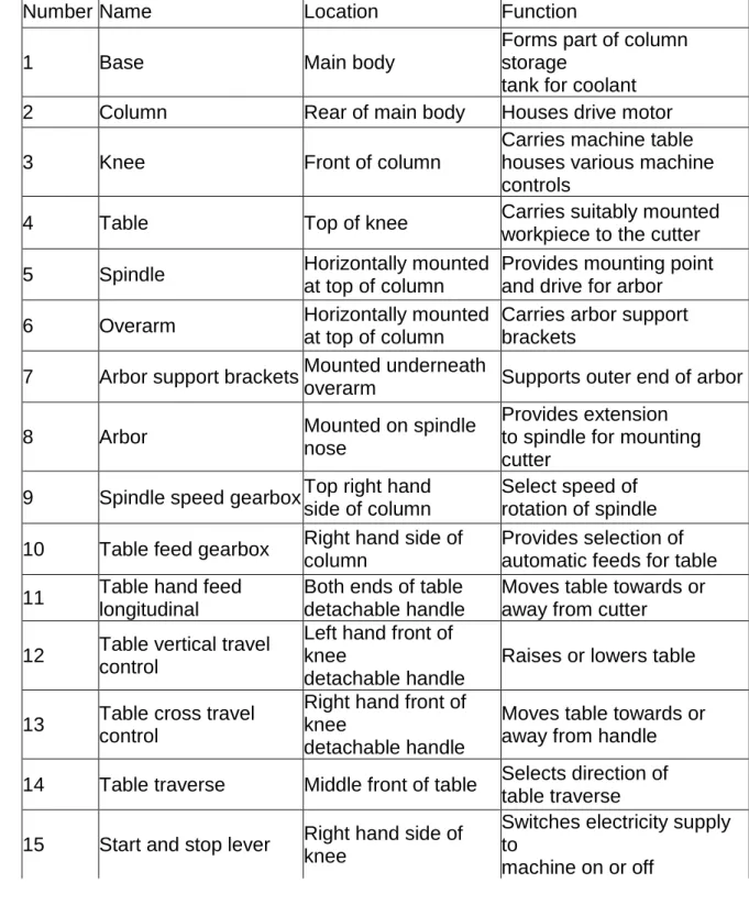
Parts of a milling machine Horizontal milling machine
The table of the horizontal milling machine moves horizontally both parallel and at right angles to the axis of spindle. This type of machine is used for machining horizontal and vertical faces and slots.
Identification of main parts
Number Name Location Function
1 Base Main body
Forms part of column storage
tank for coolant 2 Column Rear of main body Houses drive motor
3 Knee Front of column
Carries machine table houses various machine controls
4 Table Top of knee Carries suitably mounted
workpiece to the cutter 5 Spindle Horizontally mounted
at top of column
Provides mounting point and drive for arbor 6 Overarm Horizontally mounted
at top of column
Carries arbor support brackets
7 Arbor support brackets Mounted underneath
overarm Supports outer end of arbor
8 Arbor Mounted on spindle
nose
Provides extension to spindle for mounting cutter
9 Spindle speed gearbox Top right hand side of column
Select speed of rotation of spindle 10 Table feed gearbox Right hand side of
column
Provides selection of automatic feeds for table 11 Table hand feed
longitudinal
Both ends of table detachable handle
Moves table towards or away from cutter
12 Table vertical travel control
Left hand front of knee
detachable handle
Raises or lowers table 13 Table cross travel
control
Right hand front of knee
detachable handle
Moves table towards or away from handle 14 Table traverse Middle front of table Selects direction of
table traverse 15 Start and stop lever Right hand side of
knee
Switches electricity supply to
Vertical milling machine
The vertical milling machine has the spindle mounted vertically at right angles to the table. Most work on this type of machine is done by using end and face milling cutters.
Number Name Location Function
1,2 As stated for
horizontal
Main body and column 3, 4 milling machine 5 Spindle Vertically mounted in head Provides mounting and drive for cutter 9,10,11, As stated for
12,13,14 horizontal milling Column, knee and table
15 machine
16 Vertical head Mounted on top
front of column Houses spindle
17 Spindle vertical adjustment handle Front of vertical head Provides vertical traverse for spindle
Working devices Machine vice
To set up:
isolate machine
make sure you are wearing protective clothing
make sure that the machine bed and Tee slots are clean and free from swarf
select suitable vice and Tee bolts for the task:
large heavy cuts need a bigger vice
a 13mm high tensile bolt will hold most jobs - mild steel studding can easily shear under heavy cuts
do you need to set the vice at an angle later on? Use a vice with angular adjustment, but make sure it is set to zero and the bolts are tight
clean the underside of the vice
always use correct lifting
techniques when handling heavy objects like vices. It is best to use a lifting trolley
check condition of bolts, washers and nuts before using them
align the vice using:
tenons - accurately made blocks that fit into the base of the vice and engage with the tee slots
dial test indicator - accurate method but can be time consuming
now set the work on parallels and tap down with a hide or nylon faced mallet until the parallels are just trapped. Listen for the change in sound when the work is seated on the parallels.
Clamps, angle, plates and parallels
To set up:
use clamps and parallels when the work is too big for the vice
tenons may be placed in tee slots to align work
dial test indicator may also be used, where tenons may not be sufficiently accurate
always ensure that clamps are fully engaged and overhang is kept to a minimum.
Finding the edge Vertical milling:
use a piece of dowel ground to 6mm diameter mounted in a chuck in the spindle, blue it up (coat it in a thin layer of engineers' blue) and have the spindle rotating
Approach the edge of the work very slowly. When the blue is
transferred to the work the centre of the spindle is exactly 3mm away from the edge. Withdraw spindle and stop machine
Zero the dial or digital readout, move in 3mm, re-zero, the centre of the spindle is now exactly in line with the work.
There are also sets of "wobblers" or edge finders on the market which make the job easier.
Horizontal milling:
set cutter in milling machine, ensuring machine is isolated
approach edge of work with cutter
using a 0.1 mm feeler gauge place it between cutter and work to feel when gauge is just trapped
drop bed to clear work
zero dial and move in 0.1 mm, the edge of the cutter is now exactly lined up with the edge of the work, re - zero the dial.
Cutting tools Horizontal milling
Type of cutter
Description Used for Remarks
Slab or roller mill
Wide cutter Facing large areas No teeth on sides Side and face cutter Teeth on sides as well as face General milling, grooves and shoulders Can have straight staggered teeth Angle cutter Teeth set at an angle Producing angular faces and Vees 45°, 60° or 90° angles most common
Slitting saw Thin cutter, like circular saw Narrow slots and cutting off Do not use a key with slitting saws
Vertical milling
Type of cutter Description Used for Remarks
Slot drill
Short, flat bottomed drill with two flutes Teeth on sides as well as face
Slotting, counterboring, spot facing, roughing for
finishing with end mill
Can drill down. Small ones can be solid tungsten carbide End mill
Similar to slot drill but having four or more flutes
Slotting, spot facing, finishing operations
Can't drill down. Can be solid tungsten carbide Shell end mill
Diameter large compared
to depth. Teeth on face and edge
Milling faces, shoulders and angles
Bored for fitting on to stub arbor
Face mill
Diameter larger than shell
mill. Teeth on face and edge
Milling faces, shoulders faces and angles
Mostly having inserted tungsten carbide teeth Solid and shell end
mills
Slot drill
Setting speeds, feeds and depth of cut The usual sequence is:
choose (or look up) the cutting speed
calculate (or choose) the feed rate
choose the depth of cut, depending on the power and condition of the machine.
The cutting speed is:
one that has been found by experiment to work best for a particular combination of tool material and workpiece material.
usually looked up in tool manufacturers reference booklets
expressed in metres per minute.
The spindle speed is:
the rate at which the spindle rotates
expressed in revolutions per minute, RPM. To work out spindle speed in RPM the formula is: Revs per minute = 1000 x Cutting speed (metres/min) 3.14 x Diameter of cutter (millimetres) Then set the machine to the nearest lower speed available. The feed rate is:
the rate at which the tool advances into the workpiece
expressed as millimetres per minute (milling machines)
more for roughing cuts; less for finishing cuts. The feed rate depends on:
the spindle speed (RPM)
the number of teeth on the cutter
the feed per cutter tooth (= the thickness of the chip in millimetres). The formula for working out the feed rate is:
feed rate, in millimetres per minute = RPM x number of teeth on cutter x feed/tooth
Then set the feed rate using the table feed gearbox.
The Abrasive Wheels Regulations (1970)
The Abrasive Wheels Regulations were brought in to reduce the number of accidents to people from
using grinding machines. They have been superseded by the Provision and Use of Work Equipment Regulations (PUWER) 1998. However, the
requirements are still valid. The main points are :
machines must have adequate guarding made from a non-shatter material (eg polycarbonate is allowed but Perspex is not)
machines must have the maximum spindle speed in RPM clearly marked on them
wheels must be made to a standard and have a standard code marked on the wheel to identify its type and maximum RPM must be marked on the wheel
all persons must be trained if they are required to mount abrasive wheels, and hold a certificate to prove that they have been trained to do so
a notice must be provided explaining the regulations and showing the minimum distance from the wheel of work rests etc.
Grinding hazards
Grinding wheels consist of:
a matrix of extremely hard particles of abrasive material (or grit) bonded together with a binder, which consists of either a glasslike vitreous material or a resin. This means that the wheel is brittle and can burst. If the wheel bursts the pieces are ejected at high speed and can cause serious injury or death.
Causes of bursting can be:
over speeding: using a wheel which is rated lower than the RPM of the machine
Cracked or damaged wheels: if a wheel is cracked it will burst. Always tap a wheel with a non-metallic object before use, it should ring. If a dull thud is heard do not use it and check with your supervisor
incorrect wheel mounting
excessive pressure: pressing too hard to try to remove metal faster can cause wheels to burst
stopping the wheel quickly by jamming an object into it
work piece moving when surface grinding. If a block of metal tilts the wheel will burst. Take care with the set -up and always double check that the workpiece is secure
side pressure, especially when using resin bonded cutting-off wheels
Incorrect storage: grinding wheels should be stored vertically when not in use.
Always use:
Guards: properly adjusted guards will contain most, of the pieces of a bursting wheel. Always ensure that the guard is in position and properly adjusted
Eye protection: goggles must be worn when grinding. Check that your goggles are marked with the latest British Standard (8S2092:2 is the current standard) or equivalent European Standard. Follow the instructions for looking after them and keep them in a safe place
lung protection: if you have to grind without coolant you will need to use an extractor and a dust mask
Arm and body protection- always wear overalls with sleeves down. A tee shirt is no protection against sparks or flying bits of wheel.
Workholding devices Surface grinding
The most common work holding method for general surface grinding is the magnetic chuck. It consists of:
a steel base with a ground flat surface
a lever to the right hand side.
The lever moves permanent magnets inside the chuck. When the lever is on the:
left it is OFF (no magnetism)
right it is ON (high magnetism).
It is best used for machining magnetic materials such as cast iron and steels. Non-magnetic materials can be ground using laminated blocks to surround the work. Laminated blocks must be placed in correct alignment; otherwise they will not hold the work.
Laminated blocks are also used when grinding vertical items where the surface area is small compared with the height.
Small items can be held by using a laminated adaptor plate. This concentrates the magnetism into smaller areas.
When setting any item on the magnetic base always thoroughly clean everything before assembly. One small particle in the wrong place can cause significant misalignment.
Other work holding devices which can be used are:
vee blocks
angle plates
machine vices
dividing heads.
Cylindrical grinding
Work holding methods for cylindrical grinding are the same as for the lathe.
Grinding wheels
Grinding wheel construction.
A grinding wheel is made from abrasive material or grit consisting of :
silicon carbide (grey) or
aluminium oxide (white).
Structure:
the size of the grit is given as a number. Smaller numbers indicate larger grain size
the binder consists of either a glasslike vitreous material or a resin bond. Resin bonded wheels can be run at higher speeds.
There are pores in the matrix of vitreous bonded wheels, soft wheels have more pores than hard ones. Wheel marking is a standardized code found on all wheels which describe them exactly. It is important to keep this to hand as it is the only way to positively identify a grinding wheel.
Wheel marking system
Example
A wheel is coded: 38A 80 LV. This means:
38A - Manufactures grit type, A means aluminium oxide
80 - Grit size
L - Medium grade of hardness
Structure code not used in this case
V - Vitrified Bond.
Wheel shapes
Straight
Taper one side Taper both sides
Recessed one side Recessed both sides Dish
Saucer Straight cup
Wheel mounting
Grinding wheels must be correctly mounted for safety. Too tight and the wheel can burst, too slack and it can come off. Only someone who has completed an Abrasive Wheels Regulations course should mount a grinding wheel.
Grinding wheels have a lead bush in the centre. Extra plastic spacers are available for adapting the wheel to a smaller spindle. Only spacers designed for the job should be used.
Blotting paper washers are attached to either side of the wheel. These are essential for proper mounting. If they are missing replacement ones should be fitted.
Surface and cylindrical grinders
On surface and cylindrical grinders wheels are changed far more often and, due to the use of coolant the paper washers need to be changed.
The wheel is not mounted directly on to the spindle. It is mounted on a two part adaptor as shown in the diagram.
Wheel balancing
Grinding wheels rotate at high speed and their construction means that there can be light and heavy spots. This can cause vibration, which in turn causes poor finishes. Balancing can eliminate or reduce this problem.
Surface grinding operations Grinding action
Grinding wheels cut like a milling cutter:
each grain of abrasive acts as a small milling cutter tooth
the binder holds them together
the voids or pores contain the chip while it is being removed. As grains wear they break away and new ones are uncovered. Grains are not an ideal shape or angle for efficient cutting so a lot of heat is generated. This prevents large cuts being taken.
Coolant is essential when grinding - both to avoid overheating the material and to keep the dust down.
Grinding applications
Application Reason
Finishing The many cutting 'teeth' and the high speeds of grinding wheels means grinding is used to obtain fine surface finishes.
Accuracy
Grinding, because it can remove a very small amount of material, can be extremely accurate. Dials on grinding machines are normally marked in 0.002mm steps.
Cutting hard materials
Many difficult materials can be cut by grinding and it is used to produce accurate results. Often hardening and heat treatment produce
distortion, which can be corrected by grinding.
Cutting off Resin bonded wheels are used for cutting off hard materials using a surface grinder for precision work. Fast cutting rates can be achieved.
Preparing to measure Safety
Before you start to measure any component:
remove any burrs or sharp edges
if it is hot, allow it to cool down.
If the component is part finished, and still held in a machine tool:
isolate the machine
move cutting tools well out of the way
remove any swarf away from the areas being measured
clean off any coolant.
Choose your measuring system
The two systems of linear measurement used in engineering are the:
metric system - most commonly used
imperial system - used in some circumstances.
The metric system
All measurements are made in millimetres and decimals of a millimetre.
A millimetre is:
a thousandth part of a metre
written using the abbreviation mm
Do not use fractions of a millimetre - instead of % mm use 0.25 mm.
Very small dimensions are expressed in microns. This is a millionth of a metre - a thousandth part of a
millimetre. This is often used as a unit of surface finish.
Check the measuring equipment
Before you start to measure, check the equipment and make sure:
the equipment is within current calibration dates
the instruments are correctly zeroed
the equipment is not damaged.
If you find that the equipment is faulty or damaged, report this to your supervisor, do not attempt to adjust it yourself.
Store measuring tools safely in their original case, and in a clean dry place when not in use.
Digital electronic measuring instruments advantages and disadvantages.
Advantages
easy to read
metric/imperial conversion at the touch of a button
easy to zero
generally more reliable
digital instruments can be preset to a false zero, useful when measuring steps
they can be connected to computers to record and analyse statistical inspection data.
The imperial system
For most engineering applications the most important units are the foot and the inch.
an inch is
approximately 25.4 mm
a foot is approximately 305 mm
there are 12 inches in a foot.
Dimensions are expressed in:
whole feet and inches, e.g. 3 feet 4 inches (or 3' 4") just inches fractions of an inch, e.g. 3/16" decimals of an inch, e.g. 0.1875"
Disadvantages
if the instrument has been incorrectly zeroed, all measurements will be out by that amount
if used to measure a moving dimension, e.g. runout on a lathe, all the user sees is a confusing mass of constantly changing numbers. An analogue instrument such as a Dial Test Indicator (DTI) is better for this type of reading.
Rules
are made from tempered stainless steel and have a non-glare satin chrome finish
usually have both metric and imperial graduations
engraved on alternate sides
have edges ground flat to measure straightness
are the quickest way to measure components to within about ± 0.5 mm
(± 0.020 in) and are used extensively for making rough measurements.
Tapes
Roll-up tapes are used for measuring long lengths up to a maximum of 30 mm (100 ft).
Measuring tapes are made with imperial and metric scales painted onto a steel blade. Shorter tapes of about 3 m (10 ft) may be graduated in 0.5 mm (1/32 in) intervals, while longer tapes may be calibrated in 1 mm (1/16 in) intervals. It is difficult to read a tape over a long distance accurately as the tape may sag, expand or not be held straight. A tape rule would be suited to measuring items such as:
the length of steel barstock on delivery
Callipers
Callipers are tools which:
have two high quality steel arms with rounded ends
are used to measure features which are inaccessible with other tools.
The distance between the ends of the arms can be adjusted to fit a component's size (either externally or internally). The size is then transferred to a suitable measuring tool (e.g. a rule or a micrometer) and a reading taken,
accuracies of about 0.5 mm (1/64 in) can be achieved.
Both internal and external callipers are made as either spring or firm-joint type.
Common uses of external callipers are for measuring:
diameters of pipes
recessed bores
undercuts which would otherwise be inaccessible.
Transferring measurements with callipers
When transferring a measurement, the calliper legs are set to touch the work's maximum dimension. The size is then transferred to a rule or micrometer and checked.
Feeler gauges
Feeler gauges are generally supplied as sets of shims (very thin pieces of high quality steel). Each shim has a different thickness and can be inserted into a small gap to check its width.
To use feeler gauges:
put a thin feeler gauge into the gap being measured
if the thin gauge goes in easily, a thicker gauge is tried.
Repeat the process until the thickest possible gauge is found which can be inserted - this indicates the size of the gap. Feeler gauges can be used with squares to check a right angle for accuracy.
Profile gauges
Profile gauges are used to check the accuracy of shapes.
The most common profile gauges are:
radius gauges
screw pitch gauges
point angle gauges.
To use, select each gauge in turn from the appropriate set and compare with the work. The gauge is then held against the job and viewed with daylight in the background. The differences in profile can easily be seen and an
assessment made of the shape of the work surface.
Plug gauge
This gauge is used for checking that holes and bores are within the specified tolerance.
A typical plug gauge has two machined diameters, one on each end. The "go" end of the gauge is machined so that it will just fit into a hole equal to the low limit required and the "not-go" end is machined so that it is
very slightly larger than the high limit required. For a hole to be within tolerance it must:
accept the go end of the gauge
Screw thread gauges
These are limit gauges made specifically for checking screw threads. They are more complex than the gauges used for plain dimensions since they have to check the form of the thread as well as the size. The three main types are ring, plug and calliper gauges.
Ring gauge
Plug gauge
Protractors
Protractors measure angles. One complete rotation is 360 degrees. One degree can be subdivided into 60 minutes of angle.
Angles can be measured using an adjustable protractor. Place the base on one side of the angle and adjust the blade of the protractor to lie along the other side. Read the angle from the circular scale.
A plain adjustable protractor is capable of measuring angles with an accuracy of half a degree (30 minutes of angle).
A vernier protractor has a vernier scale and can measure angles to an accuracy of one twelfth of a degree (5 minutes of angle).
The scale in the illustration shows a reading of 52 degrees 40 minutes.
Vernier callipers
A vernier calliper consists of two basic parts:
a beam with a jaw at right angles (the-beam jaw)
a moveable jaw which slides along the beam.
There may also be a clamping block. This can be clamped to the beam so that the fine adjustment wheel can be used to accurately adjust the position of the moveable jaw.
For measuring internal dimensions use the nibs on the ends of the jaws, and remember to make an allowance for the thickness of the two nibs. Some vernier callipers have separate 'internal' jaws that will give direct measurements of bores and groove widths.
Micrometers
Micrometers can normally measure to within 0.01 mm (0.0005 in), although some are more accurate. Always check the zero reading before using a micrometer, and see that the anvil and spindle are clean. If the zero reading is inaccurate, inform your supervisor.
The range is normally 25 mm, and the common sizes are: 0-25 mm, 0-25-50 mm, 50-75 mm and so on.
The metric micrometer
Each time the thimble is rotated the spindle moves by 0.5 mm. The barrel is marked with a line for each turn of the thimble.
The bevelled edge of the thimble is marked with 50 divisions, so each one
represents a movement of the spindle of 0.01 mm.
This illustration shows a micrometer reading of 21.92 mm.
Surface texture comparison plates
Surface texture comparison plates are sometimes called scratch blocks. Each plate contains several samples of surface textures produced by various
machining methods to varying degrees of surface roughness. Each surface will represent a specified roughness average (Ra) value.
To use, select an appropriate plate and compare with the roughness of the work by visual examination and comparative scratching using a fingernail. When the surface on the plate most similar to the work is found, its surface texture can be read off as a number. The number is the Ra value, given in micrometres (Ilm).
The ranges of Ra values for common processes are:
Process Ra value of finish (µm) Grinding 0.05-0.8 Finish machining 0.4-1.6 Rough machining 3.2-12.5 Forging/casting 1.6-50
Surface texture comparison plates are available for checking the surface texture of most machining processes.
Slip gauges (Gauge blocks)
Slip gauges are extremely accurate blocks of hardened steel. They are kept in sets, and the blocks can be built up to form a pack of almost any required size. They are used to check the accuracy of measuring instruments. Checks are usually done at approximately 10%, 50% and 90% of the range of the instrument. On a 0 -150 mm vernier calliper for example, checks would be done with slip gauge packs of 15 mm,
75 mm and 135 mm.
Some sets have a pair of 'protector' blocks. These are two identical blocks made from a wear resistant material (such as tungsten carbide) that are used as the two outside blocks of a pack. In this way errors caused by wear on the blocks are reduced.
Slip gauge sets are produced to different standards, some are 'workshop' quality and some are 'inspection' quality.
Dial test indicators (DTls)
DTls have a spring loaded plunger (or lever) connected to a pointer that rotates round a dial. A plunger type has a typical range of 0 - 12 mm, and divisions can be as fine as .002 mm. Typical uses are to check parts for concentricity, roundness or alignment. Lever types tend to have a smaller range, and would be used to check things like the 'run - out' of bores.
The illustration shows a DTI mounted on a magnetic base and being used to check the roundness of a bar.