INTRODUCTION
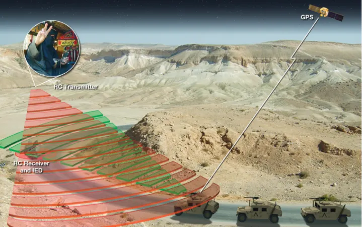
Improvised explosive devices (IEDs) have become an increasingly popular weapon of choice for insurgents and small armed forces over the past few decades. A favorite type of IED used in U.S. coalition theaters of operation today is the RF or radio-controlled (RC) com-mand link. These IEDs are inexpensive, easy to build or acquire, and difficult to trace and can be triggered from long distances, keeping the operator safe from any detonation or exposure to U.S. military forces. An RCIED is simply explosive material that is integrated
with a handheld wireless radio or device that will trigger upon receipt of a signal from a second wireless handheld device. These RCIEDs have caused many fatalities and injuries to U.S. forces and coalition partners.
APL has significant history and depth of knowl-edge in the areas of RF propagation, electronic warfare (EW), electronic attack, and communication protocols. Because of this knowledge, APL was selected to provide technical guidance and lead development of jamming techniques for all RCIED countermeasures developed by
he systems engineering process consists of several phases designed to develop
a system or deliverable product through its entire life cycle, from needs
defini-tion through system disposal. Throughout this process, each phase plays a
key role in the development and ultimately the operational success of the system.
Fail-ure to use systems engineering principles and procedFail-ures can result in numerous risks,
including a delayed schedule, increased costs, a technically inferior product, and,
poten-tially in this case, increased loss of human life. To improve our technical understanding
of the fundamental issues, principles, and phenomena, as well as to provide greater
support to the frontline warfighter, APL has adopted a systems engineering process in
its Counter Radio-Controlled Improvised Explosive Device Electronic Warfare (CREW)
program. This article describes the systems engineering process used by CREW and
how the process has improved both overall efficiency of development and product
qual-ity through its implementation in a quick-reaction or rapid-prototyping environment.
Systems Engineering in Counter Radio-
Controlled Improvised Explosive Device
Electronic Warfare
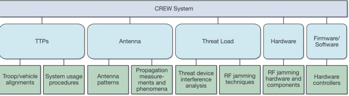
The vast majority of CREW systems are used in dismounted (man-pack) and mounted (vehicle-inte-grated) configurations. Although the capabilities vary between the two configurations, the operational con-cept is identical. The CREW system continually scans the environment for signals believed to be those of a threat device trigger. When a suspect signal is located, the system projects energy at the target receiver in an attempt to disrupt communications. Each part of the CREW system shown in Fig. 2 is integral in successfully defeating the target device.
Figure 2 depicts the CREW system broken down into its individual components. APL leads and is responsible for all tasking in the five subsystems/areas shown with the exception of tactics, techniques, and procedures (TTPs). In the case of TTPs, these are developed by the U.S. Marine Corps with little to no input from the APL CREW team. As shown, there are five subsystems that make up the overall CREW system.
• TTPs: TTPs are used by troops on foot, as well as
vehicle convoys, to increase the chances of detect-ing IEDs and of survivdetect-ing IED detonations. These procedures, while not tangible hardware or software components, are an integral part of the system and its usage.
• Antennas: Antennas are arguably as important
as the anti-RCIED hardware itself. Antennas with the U.S. Marine Corps’ Counter-RCIED EW (CREW)
program. Significant time and effort has been placed into countering this threat using both tactics and tech-nology. Unfortunately, RCIEDs continue to evolve as quickly as they are countered. The rapid evolution of technology and insurgent tactics creates user needs that must be met in a matter of days or weeks, not months. To successfully continue to counter these advances, the APL CREW team developed a rapid cycle, starting with needs analysis, through design, development, and test, and all the way to deployment of the CREW system.
APL performs engineering analysis, modeling and simulation, hardware/software prototyping, and testing to provide science and technology guidance concern-ing current CREW systems. In turn, this also supports the development of future CREW systems. This article focuses on the high-level systems engineering (SE) and development of threat loads and techniques to be used in CREW hardware systems even though these tasks are only a small part of the APL CREW tasking. A subsys-tem of the overall CREW hardware, threat loads, and techniques make up the heart of the CREW system; they are the instructions and coding that allow the pro-duction of a communication jamming protocol for wire-less handheld devices used to trigger IEDs, and they are key to successfully countering an RCIED. The role of CREW in the context of today’s modern warfighter is shown in Fig. 1.
M. E. PESCI
The vast majority of the early CREW systems were broadband noise jammers using active-only tech-niques. Active techniques are those that project power around the system in all directions at all times, regard-less of the environment. Performance was achieved in a power-centric fashion by projecting more power on the emplaced threat receiver than the threat transmit-ter in order to disrupt communication between the two devices. Because there are multiple types of radio devices using multiple frequencies and communica-tions protocols, this approach required CREW systems to inefficiently project energy in every possible threat channel (frequency) simultaneously. Although a large portion of the RF spectrum was jammed, the jamming technique development for these early systems was rela-tively simple. It consisted of ensuring threat frequency band coverage, minimizing timing concerns due to duty cycling, and channelizing the energy to ensure jamming energy existed in every possible threat channel. All of these are constants—so, in other words, the system is always projecting energy at its target, and in most cases, just into the atmosphere in general. As a result of these systems’ characteristics, the evaluation of perfor-mance was also a simple process, a matter of determin-ing how much energy was available for each individual threat channel.
For example, for any given threat channel, deter-mining the available amount of energy to project from the CREW system was predictable. Although there were variations in effective isotropic radiated power (the amount of power that would have to be emitted by an isotropic antenna to produce the peak power density observed in the direction of maximum antenna gain) about the vehicle with a system installed in it, this could be taken into account by identifying the performance of a system empirically in the field. Field testing and verification/validation consisted of placing a threat transmitter a fixed distance from the threat receiver within the line of sight. This testing proved to be a valid and conservative method to evaluate CREW system performance accepted by the counter-RCIED community. The measure captured system range to omnidirectional patterns, low voltage standing
wave ratios, and high gain provide a better capabil-ity for the system power to reach the IED receiver and interfere with its operation and communication than do antennas with lesser characteristics. Direc-tional antennas provide even greater capability for the system power to reach the IED receiver, though at the expense of omnidirectional coverage.
• Threat load: The threat load is the technique
employed by the hardware to interfere with the IED communication link. Understanding the strengths and weaknesses of each device is critical, which is why each possible threat device undergoes an inter-ference analysis to determine the most efficient way to interrupt its communications protocols. Tech-niques must balance power and capability because not all communication devices operate identically or with the same protocols. Developing multiple tech-nique packages that can negate the communications link between dozens of devices is necessary to ensure that the troops are covered in any location or ter-rain and under varying circumstances. These tech-niques, and the commands that control the system hardware, are known as threat loads.
• Hardware: The hardware is the jammer itself and all
of its associated material components. Each vendor system is thoroughly analyzed and characterized by APL for strengths and weaknesses to most efficiently make use of its capabilities. Individual internal com-ponents are analyzed separately as well to understand how they contribute to overall system performance.
• Software/firmware: Software and firmware are the
hardware controllers. Modifications, upgrades, and changes to firmware may improve performance by unlocking or allowing additional capabilities not originally possible with earlier software/firmware iterations. Understanding how the software/firm-ware controls the hardsoftware/firm-ware is essential to under-standing system performance and thus system effectiveness.
TTPs
Troop/vehicle
alignments System usage procedures
Antenna Antenna patterns Propagation measure-ments and phenomena Threat Load Threat device interference analysis RF jamming techniques Hardware RF jamming hardware and components Hardware controllers Firmware/ Software CREW System
and allowing for improved requirement traceability in the final product. It takes valuable time to incorporate traditional practices into CREW tasks and deliver-ables. As military operations in Iraq and Afghanistan began, the timeline for APL to develop a CREW prod-uct could be as short as 4 weeks. Traditional SE pro-cesses would require full and extensive use of product documentation, reviews, meetings, plans, analyses, etc. Although all steps in the process are important when producing an acceptable product, streamlining the scope of each phase and adding in key checkpoints to ensure product quality without extended use of time become paramount.
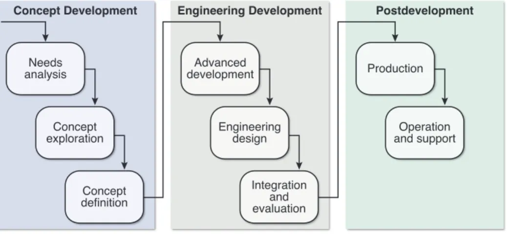
Kossiakoff describes the SE process in eight phases as shown in Fig. 3: needs analysis, concept exploration, concept definition, advanced development, engineer-ing design, integration and evaluation, production, and operation and support. Even though the exact same terms were not used, this approach was the basis for the development of the APL SE loop that is highlighted in this issue of Johns Hopkins APL Technical Digest. In the APL SE loop, critical needs and capability assessment is conducted in the concept development block shown in Fig. 3. Concept exploration overlaps both the concept development and engineering development blocks, and solution validation/implementation is conducted during engineering development. As will be discussed later, deployment, which is not an APL CREW task, falls into the postdevelopment block.
To contrast the modification in the SE process used in CREW, we summarize the traditional process and phases shown in Fig. 3.
• Needs analysis: Defines the need for a new system—
system studies, technology assessments, and opera-tional analyses
• Concept exploration: Examines potential system
concepts—concept synthesis, feasibility experi-ments, and requirements definition
effect and provided a “best guess” as to the distance at which the system was effec-tive against a given device or devices. Test scenarios were worst case for the CREW system and proved to be a successful method of evaluating performance.
As time went on, the number of threats, threat complexity, communica-tion protocols, and threat frequency bands used all increased. The technologi-cal demand on the early active jammers became too
great, and their performance deteriorated. Fortunately, new CREW systems using reactive technology were developed by engineering firms and commercial ven-dors that could protect troops from the growing number of RCIED-based threats. These reactive systems are able to focus their power only on a single threat channel when triggered rather than spreading it over the entire threat band, because the systems are able to monitor and “listen” to the electromagnetic environment to detect threat signals.
With the increased complexity of the CREW systems, the methodology used to develop jamming techniques and evaluate system performance had evolved as well. Prudent SE processes and principles are used to ensure success throughout the development life cycle. However, time is a significant constraint, so the systems engineer-ing process has been adapted to quick-reaction systems development. There is a simplicity to the analysis and speed at which new threat devices are being utilized and customized by insurgents and other forces. When cou-pled with the quick response and turnaround required by sponsors and users, this dictated that a streamlined SE process be developed and used during recent CREW hardware and software development.
For the most part, currently accepted SE process and life cycle models such as EIA-6321 and IEEE-ISO-152882 detail the SE process for long development cycles but leave quick-reaction tasks up to the systems engineer, who tailors them to the individual project. For the CREW development cycle to remain at 6–8 weeks at the most, these processes were streamlined while still retain-ing the core principles and practices.
SYSTEMS ENGINEERING IN COUNTER-RCIED
“The function of systems engineering is to guide the engineering of complex systems.”3 Implementation and usage of SE principles and practices have proven to reduce overall project risk while increasing efficiency
Concept Development Engineering Development Postdevelopment
Needs analysis Concept exploration Concept definition Production Operation and support Advanced development Engineering design Integration and evaluation
M. E. PESCI
system upgrades. Postdevelopment (production and operations/support) tasks are carried out by the U.S. Marine Corps or their designated support.
CREW QUICK-REACTION SYSTEMS ENGINEERING
CREW systems development is almost always of the “quick-reaction” type—that is, the time from when a need is realized to when a completed product, or tech-nique, is available is measured in weeks, not months or years. In some cases, SE phases may converge or overlap because multiple tasks are simultaneously in progress.
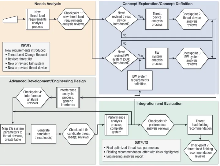
The development of a technique or “threat load” in a CREW system is multifaceted and follows the tra-ditional SE process phases. Threat loads subsystems include the commands, instructions, and techniques used by CREW hardware to defeat RCIEDs. The streamlined process used by APL when developing a threat load is shown in Fig. 4. Each colored block rep-resents approximately 1.5 weeks, for a total of no more than 6 weeks from needs analysis and requirements development to delivery of the final threat load. This
• Concept definition: The preferred concept is
selected and defined—trade-off analysis, functional architecture, and subsystem definition
• Advanced development: Identifies and reduces
development risk—risk abatement, subsystem dem-onstration, and component design requirements
• Engineering design: Detailed engineering design—
component engineering, component testing, and reliability engineering
• Integration and evaluation: Integrates the
compo-nents into a functioning system and evaluates that system in a realistic environment—system integra-tion, prototype testing, and operational evaluation
• Production: The system is manufactured and
pro-duced—tools and test equipment, production and acceptance, and system delivery
• Operation and support: The products of the
system development and production phases per-form the operational functions for which they were designed—system operation, logistics support, and
Integration and Evaluation Needs Analysis Threat device analysis process New/ revised threat device introduced? New/ revised EW system (SUT) introduced? EW system analysis process Checkpoint 2: threat device analysis reviews Checkpoint 4: interference analysis reviews Checkpoint 5: candidate threat load(s) reviews Checkpoint 6: performance analysis reviews Checkpoint 7: threat load fielding
recommendation reviews New requirements introduced:
• Threat Load Change Request • Revised threat list • New or revised EW system • New or revised threat device
INPUTS
Checkpoint 1: new threat load
requirements analysis reviews New threat load requirements analysis process Interference analysis process, generic interferers Performance analysis process, complete system Checkpoint 3: EW system analysis reviews Yes Yes No No
Concept Exploration/Concept Definition
EW system requirements definition Threat load fielding recommendation Generate candidate threat load(s) Map EW system parameters to threat devices, create table
• Final optimized threat load parameters
• Fielding recommendation letter with risks highlighted • Engineering analysis report
OUTPUTS
Advanced Development/Engineering Design
various intelligence sources. This request, in the form of a Threat Load Change Request, may come from APL, the government, or the user in the operational forces. The need may be created by an advance in wireless tech-nologies, adaptation of new communications protocols, deficiencies or changes to current anti-RCIED hardware, or a “find” by U.S. or coalition forces, such as an unex-ploded emplaced IED or an uncovered weapons cache. A formal Plan of Action is developed detailing proce-dures APL will follow in researching and developing the new technique. The Requirements Analysis Review ref-erenced at checkpoint 1 is conducted informally during an internal meeting of APL engineers.
Concept Exploration
In the concept exploration phase, an analysis of alter-native techniques consisting of research into use of cur-rently existing techniques and threat loads, modified existing techniques, and newer experimental techniques is conducted. Analysis of the threat RC device and any changes to the RCIED jamming system hardware begins. Analysis results are traced back to the needs and requirements to verify that the capability exists to defeat the device and disrupt its communication link using current technology. Through communication with the is to be compared with a full SE process, which, when
applied to threat load development, takes approximately 12–16 weeks, depending on problem complexity. While efficiency and speed have increased, product quality has not decreased. More focus on the technical aspects of the hardware, software, physics, and RF phenomena allow for increased product value and quality while also decreasing the time engineers are required to spend in meetings or on other endeavors that may otherwise cause a loss of focus.
The CREW SE process has many phases that will occur simultaneously, overlapping as necessary. This overlap has resulted in a minimum 50% reduction in response and delivery time, placing the RCIED-defeating technique into the hands of the warfighter in approxi-mately half the time. SE reviews occur at checkpoints via teleconferences or, if possible, through informal internal meetings that, in many cases, are attended by govern-ment representatives. This process is described through individual SE phases and described in greater detail in Figs. 5 and 6.
Needs Analysis
In this phase, a need for an updated counter-RCIED threat load and technique is determined on the basis of
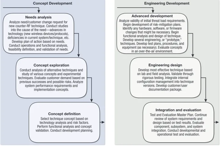
Advanced development
Analyze validity of initial threat load requirements. Begin development of risk-mitigation plans. Identify any hardware, software, or firmware changes that might be necessary. Begin functional analysis and design of technique. Develop several engineering, or “prototype,” techniques. Develop test plans, procedures, and
equipment (as necessary). Evaluate concepts in an over-the-air environment.
Engineering Development
Engineering design
Develop most effective technique based on lab and field analysis. Validate through
rigorous testing. Integrate internal configuration management into technique
versions. Develop customer/user documentation package.
Integration and evaluation
Test and Evaluation Master Plan. Continue review of system requirements and design based on test results. Evaluate
component, subsystem, and system integration. Conduct developmental and
operational test and evaluation.
Figure 6. CREW engineering development.
Needs analysis
Analyze need/customer change request for new counter-RF technique. Conduct studies into the cause of the need—advances in technology (new wireless devices/protocols), deficiencies in current system/technique, etc. Develop plan of action based on needs. Conduct operations and functional analysis, feasibility definition, and validation of needs.
Concept Development
Concept exploration
Conduct analysis of alternative techniques and study of various concepts and experimental techniques. Evaluate customer demand based on
previous successes and possible risks. Analyze system performance requirements and
implementation concepts.
Concept definition
Select technique concept based on technology analysis and risk factors. Perform functional analysis and concept validation. Conduct development planning.
M. E. PESCI
informally at APL, usually with representation from government personnel.
Integration and Evaluation
The Test and Evaluation Master Plan is completed by APL and delivered to the sponsor. Test readiness reviews are held via teleconference, and operational assessment testing is conducted by the sponsor with APL as the technical advisor. Upon successful completion of the operational assessment, the test data are analyzed by APL to verify performance seen in the field and pre-sented to the customer. The threat loads are then for-mally delivered to the customer with a recommendation for fielding and a formal Engineering Analysis Report detailing the results of the entire process.
Postdevelopment (Production/Operation and Support)
APL has no specific tasking in this phase. Once the threat load is delivered to the customer, it is incre-mentally installed into vehicles in theater based on need, location, and vehicle availability. All service and updates are then conducted by Field Service Represen-tatives of the U.S. Marine Corps. Should issues arise, APL may be contacted for investigation and support, but any nontechnical or logistical matters are handled by the government.
The final quick-reaction process is a result of several changes and modifications to the traditional SE pro-cess. Each phase overlaps with the preceding phase as well as the next phase. This allows parallel efforts to increase process efficiency, though it relies on the avail-ability of necessary resources. Reviews are informal, and checkpoints may be considered reached while work is still ongoing. The speed and flexibility of these changes allows for a more efficient process. However, its success hinges on the experience of the team members involved and their familiarity not only with the process, but with all technical aspects of the system, subsystems, and com-ponents as well. Any deviations from the abbreviated process will delay the schedule and inevitably increase overall cost.
CONCLUSIONS
The classical SE process allows for an efficient system development process; however, many of today’s tasks and projects require an accelerated version of the pro-cess capable of rapidly producing a cost-effective and technically capable solution. The modern warfighter cannot wait months for an in-depth research and design process because many of the requested capabilities are needed in the field as soon as possible. Although clas-sical SE processes apply the necessary rigor to develop a quality product, without some modification, this type of customer and the user, as well as analysis of previous
suc-cesses, APL can mitigate the risk of developing a less effective technique by incorporating known successful techniques as appropriate. Constant communication with the customer and user is essential to risk reduction throughout each stage. Threat Device Analysis Reviews and EW System Analysis Reviews referenced at check-points 2 and 3, respectively, are again conducted infor-mally and internally by APL engineers.
Concept Definition
Once the concept design has been chosen, it is formally defined and documented. User documentation detail-ing individual RF devices mapped to system anti-RCIED hardware capabilities helps the user understand how the system will attack the threat device and assists the user in developing their TTPs for actual usage in the theater of operation. Planning begins for operational assessment testing at a government test site at this early stage.
Advanced Development
Analysis is again performed on the initial require-ments to verify they can be met on the basis of evalu-ation of the anti-RCIED hardware capabilities and the subject threat device technical characteristics and com-munication protocols after an interference analysis. Risk analysis is also performed to reduce potential impact on cost and schedule later in the cycle. Mapping of EW system parameters to threat devices is finalized, and any required custom analysis/test software is developed. Pro-totype, or “engineering,” threat load system development begins, and various test loads are created. In addition to exploration of concepts in the laboratory and anechoic chambers, over-the-air evaluations are conducted at an outdoor site using the actual anti-RCIED hardware and both real and simulated threat devices. Performance measurements, propagation patterns, system minimum detectable signal, and various other measurements are taken. This is not, however, an operational assessment— it is simply an evaluation of the engineering test loads and way of reducing risk before the engineering design and integration and evaluation phases. This advance testing reduces the overall design time and shortens the overall process.
Engineering Design
Threat load requirements are reviewed again. Propa-gation issues that may reduce or enhance technique effectiveness, such as vehicle shadowing and antenna patterns, are evaluated. The technique believed to be most effective based on all evaluations to this point is developed into a threat load and component documen-tation packages. A review of the final technique and threat load referenced by checkpoint 5 is conducted
ACKNOWLEDGMENTS: I thank F. Lombardi (APL) for provid-ing the original diagram on which Fig. 4 is based.
REFERENCES
1Electronic Industries Alliance, EIA Standard: Process for
Engineer-ing a System, EIA-632, Electronic Industries Alliance, ArlEngineer-ington, VA
(1999).
2International Organization for Standardization (ISO)/International Electrotechnical Commission (IEC)-Institute of Electrical and Elec-tronics Engineers (IEEE), Systems and Software Engineering—System
Life Cycle Processes, ISO/IEC 15288:2008(E)/IEEE Standard
15288-2008, ISO/IEC-IEEE (2008).
3Kossiakoff, A., Sweet, W. N., Seymour, S. J., and Biemer, S. M.,
Sys-tems Engineering Principles and Practice, John Wiley & Sons,
Hobo-ken, NJ (2011).
procedure can become cumbersome and lengthy when all phases and facets are conducted to their full extent. CREW demonstrates how APL has modified the SE process to enable quick-reaction development capabili-ties that satisfy the challenging requirements of today’s quickly changing battlefields. The result has been a series of analyses, techniques, studies, and products that have helped to greatly reduce RCIED casualties and injuries on the battlefield. The efficiency with which these products are delivered, combined with our con-tinually increasing breadth of technical and operational understanding of the RCIED problem space, led to APL becoming the premier organization for confronting the most difficult RCIED problems.
Michael E. Pesci is a member of the APL Senior Staff in the Sensor and Weapon Integration and Test Group in the Air and Missile Defense Department. He has contributed to various radar and network projects at APL, such as the Cooperative Engagement Capability (CEC), as well as ground and airborne electronic attack programs, including both the U.S. Navy and U.S. Marine Corps CREW programs. He is currently the Project Manager for the U.S. Marine Corps CREW pro-gram and continues to provide SE expertise to this and other CREW propro-grams at APL. His e-mail address is [email protected].
The Author
Michael E. Pesci