Chapter 5
UMTS Network Architecture
A network architecture for all FPLMTS has been developed which is capable of
supporting all proposed and anticipated future satellite systems. The development of this single network architecture for all FPLMTS was seen as the best way to achieve a high level of inter-working between the networks of different designs and capabilities. It was developed in Europe by the Race Monet project to meet the requirements of UMTS defined by ETSI SMG5. ITU-R TG8/1 has yet to study the FPLMTS network
architecture but it is hoped that it will take its lead from ETSI SMG for these aspects. A comprehensive description of the network and functional support of satellite access is given in a Race Monet report [D112].
5.1.
The UMTS Network Architecture
CSS FES
BS SAT
LE
Radio access networks Core network
MT
SCP DP
UNI
MT Mobile terminal UNI User to network interface
SAT Satellite link
BS Base station DP Data point
FES Fixed Earth station SCP Service control point
CSS Cell site switch LE Local exchange
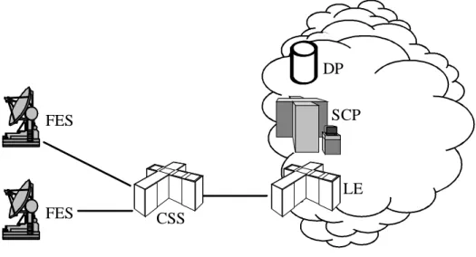
The network architecture defines entities that are likely to be collections of physical equipment located in one place. Figure 20 shows the sites of these entities and shows the physical links between them. The network architecture also defines the functions that each of these entities must perform and their interfaces with each other so that the entities in each network can work together to perform operations such as handover between networks [SSD].
5.2.
Justification
The lower part of the diagram in figure 20 depicts the usual terrestrial arrangement of sites in mobile networks. In cellular networks such as GSM the CSS handles co-ordination, concentration and inter-working with the core network and may be connected to tens of BSs. A micro or macro cellular CSS would have a SCP and DP associated with it to handle terminal mobility intelligently in a manner optimised for that cellular network. Each BS would take care of transmission layer functions using antennas at one or more cell sites.
In a pico cell environment the CSS may or may not be required. In a business
environment, such as an office building or hotel, CSS functions would be needed and handled by the cordless PBX. In the home, there is likely to be only one line available and no need for switching. In this case the BS would interface directly with the LE (local exchange) through a fixed telephone line.
The LE is the interface of any access network (twisted copper pairs, radio access, etc...) to the core transit network. Even though the CSS performs some switching functions it is still on the "user" side of the UNI (user to network interface). The LE is the part of the core network that handles call control such as providing dial tone and it is still required in all FPLMTS. It would often be located in the same building as a large CSS. The function of the core network "cloud" is to guarantee robust interconnection and routing of calls between LEs.
In the satellite environment, FESs are necessary to provide an interface between satellites (which in turn are connected to the mobile terminals) and networks on the ground. The FES includes (but is not limited to) the radio transceivers for the feeder links between the FES and satellites and the multiplexing of channels on those feeder links. Additional functions such as radio resource management (co-ordination with the other FESs to avoid mutual interference) and network functions (call control, network routing and location management) may or may not be included in the FES. An FES will cater for access to mobile terminals within its well-defined geographic coverage area, as discussed in section 5.5.
The coverage of an FES is a very large area, often spanning many countries. The FES is still the fixed, known entry point to an access network and is on the "user" side of the UNI. This means that the call control functions of a "local" exchange are still required. It is, however, worth noting that usually the LE equipment will be dedicated to the satellite access network and not shared with any other access means. Typically it would be co-located with the FES and connect into the core network at an international switching centre or transit exchange level, depending on the nature of the traffic expected to be carried from its coverage area. If an FES’s coverage spans many countries then much of
its traffic may require international switching to route it. If an FES covers only part of the USA or Canada then connection into a transit exchange would be more appropriate. All satellites that do not use inter-satellite links can be considered as analogous to cell antenna sites, directly connected to a BS and CSS on the ground at the FES. Just as a cellular BS and CSS can control multiple cell sites, economies can be made by enabling an FES to control multiple satellites. Whilst such economies can be realised in GEO, the use of multiple satellites by an FES is essential in non-GEO networks to allow
continuous coverage of a geographic area whilst the satellites move over it.
In contrast to the terrestrial cellular networks analogy, in many non-GEO networks it is necessary for one satellite to be controlled by multiple FESs. This requires co-ordination and synchronization between FESs and satellites but it allows an FES to guarantee coverage of a geographic area in the same way as a BS and CSS can, allowing network functions to page mobile terminals in a similar way. The coverage of various proposals for satellite systems and how they achieve this is discussed in detail in section 5.5. FESs will need to communicate with each other to effectively manage sharing of radio resources, call handover between FESs and the location of mobile terminals in areas covered by more than one FES. For example, a FES might not normally be involved with a call handled through another FES and yet it would be affected if there was a satellite handover using frequencies shared by both FESs. Clearly, some level of co-ordination is required. To do this an arrangement could be considered where a CSS role is to control a number of BS-like FESs directly, in a hierarchical model, as shown in figure 21. The CSS in figure 21 would not be the same entity (or have all the same functions) as a CSS in terrestrial radio access networks but would need to be specific to the satellite system to co-ordinate the satellites and FESs effectively.
Satellite access network Core network
FES FES LE SCP DP CSS
Figure 21 Hierarchical FES structure with separate CSSs
Given the expected large geographical separation of FESs, a better architecture is to connect each FES directly into the core network and merge the CSS and BS functions into the single FES entity. Co-ordination is performed by functional entities distributed
among all the FESs and communications for co-ordination among FESs can be carried through the core network or through the satellites themselves. This is the UMTS architecture as presented in figure 20.
5.3.
Operators in Satellite Access
The TMN (telecommunications management network) framework adopted for terrestrial FPLMTS is also suitable for satellite UMTS [MONET62]. To understand to what extent countries’ sovereignty over their UMTS service provision can be maintained, the
following operators are distinctly defined:
• Satellite operator, in charge of designing a satellite network and providing and
maintaining the constellation of satellites
• FES operator, in charge of designing and building an FES to serve a well-defined
area and obtaining necessary licences to operate in that area. The FES operator may be the same organization as the satellite operator but in most cases it will not be.
• Service provider, providing FPLMTS service to customers. Service providers are the
business identity that customers using FPLMTS see. They handle the customers’ billing and interconnection arrangements, usually co-operating with a number of terrestrial mobile network operators in many countries to enable their customers to obtain services there whilst roaming. They are the first point of contact for
customers and effectively buy network communications facilities wholesale from FES operators for re-sale to their customers. Service providers will make agreements with FES operators in exactly the same way as they deal with terrestrial mobile network operators.
• Satellite value added service providers, providing services over and above plain
communications. Satellite value-added services are likely to be different to those provided on terrestrial cellular networks. For example, position fixing and services based around this are easily provided but would not be standardized FPLMTS services.
5.4.
Managing non-GEO Satellite Motion
The UMTS network architecture shows a deceptively simple link from the FES through the satellite to the mobile terminal. For a satellite in GEO the link is indeed this simple but in any other orbit the satellite will be moving relative to the FES and mobile
terminal and it can move completely out of range. The speed of orbital motion is higher for lower altitude orbits, with a 769km altitude LEO satellite moving at an amazing 27,000km/h. As it approaches the horizon the satellite and its antenna spot beam pattern are moving at 6.6km/s relative to the FES or mobile terminal. At these speeds an
individual satellite only remains above the horizon of an FES or mobile for 5 to 10 minutes. The time it can communicate with both mobile and FES is even shorter. The transitory nature of the satellite links is indeed going to be one of the most complex aspects of non-GEO satellite networks. The UMTS network architecture restricts the complexity of this link to the satellite entity which represents a permanent connection between the FES and mobile terminal for as long as the mobile terminal is within the coverage area of the FES. The SAT entity in figure 20 therefore represents the functions of numerous satellites, possibly including inter-satellite links and on-board switching
and control. The FES is promoted as a fixed network node that handles communications with its mobile terminals. The LE and core network are never concerned with the
transport mechanism through the satellites - as far as they are concerned, the FES has a fixed coverage area containing the mobile terminal in exactly the same way as a CSS has in a terrestrial cellular network. Any satellite motion is hidden in the FES to mobile terminal link.
This is a sensible approach considering that the mobile terminal and FES will always be a matched pair, with the terminal’s equipment for handling a satellite-mode air interface being designed to a standard set by the designers of the FESs and satellites. The satellite network designers have a free hand to implement the FES’s coverage in whatever way they wish. The absence of any satellite-specific functions in the core network simplifies the task of the FES operator connecting into core network operators’ equipment.
5.5.
FES Coverage
Two assumptions have been made for satellite constellations not using inter-satellite links:
1. An FES will have more than one antenna to enable it to track and communicate through two or more satellites simultaneously. If an FES has enough antennas then at any particular instant it will be able to communicate with all mobile terminals anywhere within the footprint coverage of each satellite that contains the FES site in its footprint.
2. Each satellite will be capable of working for two or more FESs at the same time. This may mean allowing access to the same spot beams by multiple FESs at once or allowing individual spot beams to be dynamically assigned to different FESs. Multiple FES access to all spot beams is most useful if the antenna beam pattern is fixed whereas individual assignment of beams to a single FES is most useful if spot beams can be steered to dwell on geographically fixed areas.
An FES will be built by an FES operator to provide coverage over all or part of the geographic area for which that FES operator has received regulatory licence. The motion of satellites in orbit is regular and predictable so it is possible to calculate which spot beams on which satellites can be used to cover this required area at each moment. Thus an FES can choose which satellites and beams to use to guarantee contiguous radio contact with all points in its planned coverage area at all times. This plan needs to account for optimum sharing of the limited resources on the satellites between the different FESs, and the limited number of call handovers that an FES can handle between satellites that might only be useful to the FES for very short periods of one or two minutes. In this thesis the area that is planned to be covered by the FES, taking all the above into account, is called the FES’s GCA (guaranteed coverage area).
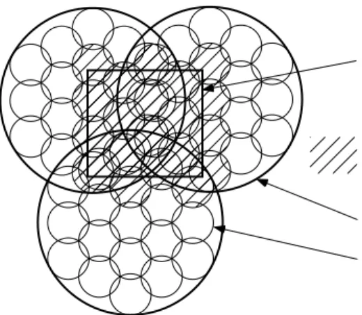
Spot beams cover quite large areas and while using a spot beam at the very edge of a GCA some area outside the GCA will be covered as well. This will only be a temporary coverage because the FES will stop transmitting through the spot beam when it is no longer useful to cover part of the GCA. Figure 22 shows the instantaneous coverage of an FES using three satellites to cover the square GCA in the centre of the diagram.
footprint spot-beam guaranteed coverage area instantaneous coverage area
Figure 22 Instantaneous coverage of an FES
5.6.
Examples of FES Coverage
Typical GCA areas must be large enough to cover the globe using a reasonable number of FESs. The size of the largest possible GCAs will be shown for four of the planned constellations (Iridium, Globalstar, Odyssey and Inmarsat-P) to prove that typical FESs’ GCAs can be big enough to allow global coverage using an economic number of
patchwork GCAs.
5.6.1.
Minimum Quality of Service
By definition, an FES’s GCA encompasses all the geographical points satisfying at any time the conditions for a minimum quality of satellite coverage. To give a mobile terminal an acceptable chance radio communication in urban or otherwise cluttered areas, a minimum elevation angle above the horizon is set for the satellites. The principle of satellite diversity was introduced in section 2.5.5 and in constellations where this is used the conditions of multiple satellite visibility will be important to guarantee a minimum quality of service and define the GCA.
The conditions for diversity are the number of satellites (one or two) that must be simultaneously in sight of both the mobile terminal and the FES. The conditions for elevation are the minimum elevation angles that are tolerated at the FES side (γFES) and
at the mobile terminal side (γMT). Elevation of the satellite should be high enough that a
mountain or a building would not hide the only satellite that could be visible to a MT. Where diversity is used, the minimum elevation of the second satellite may be specified lower than the first satellite without compromising the quality of the diverse link too much because reception is likely to be better from the higher elevation satellite anyway. At the FES side of the link very low elevation angles can be tolerated because FESs are built on sites carefully selected for their uncluttered view of the sky, often right down to 0° elevation. In this chapter γFES is chosen to be 5°.
Figure 23 plots two angles, γ1 and γ2, at all latitudes north and south for each of the four
constellations. The angle γ1 is the minimum elevation angle provided by the
constellation so that it is always possible to see at least one satellite at over γ1 degrees
satellites. The angle γ2 is the minimum elevation angle of the second highest satellite so
it is always possible to see at least two satellites over γ2 degrees.
0 5 10 15 20 25 30 35 40 45 50 55 60 65 70 75 80 85 90 0 5 10 15 20 25 30 35 40 latitude [deg] elevation [deg] Iridium 0 5 10 15 20 25 30 35 40 45 50 55 60 65 70 75 80 85 90 0 5 10 15 20 25 30 35 40 latitude [deg] elevation [deg] Globalstar 0 5 10 15 20 25 30 35 40 45 50 55 60 65 70 75 80 85 90 0 5 10 15 20 25 30 35 40 latitude [deg] elevation [deg] Odyssey 0 5 10 15 20 25 30 35 40 45 50 55 60 65 70 75 80 85 90 0 5 10 15 20 25 30 35 40 latitude [deg] elevation [deg] Inmarsat P
Figure 23 Minimum elevation angles available 100% of the time for
one satellite (γ1 = upper curves) and a second satellite (γ2 = lower curves) for diversity
It is clear from figure 23 that the satellites’ elevations and therefore the probability of obtaining a clear line of sight radio path to one or two satellites is dependent on the FES’s position. Figure 23 shows variations with latitude - there is very little variation with longitude because the Earth rotates underneath the constellation so over time any differences in satellite geometry to the east or west will average out. An FES operator building an FES to cover a GCA at a certain latitude will be able to calculate the minimum values of γ1 and γ2 in the GCA and calculate the link power budget for these
local conditions of diversity and probabilities of shadowing. Permanent link margins could then be optimized to suit the FES location and provide maximum capacity from the satellite system.
For very good availability of service with only one satellite link, the EU Race Saint project proposed that the elevation angle γMT should be at least 20°. The upper curves in
figure 23 show that this is always possible for Globalstar between 30° and 62° latitude and for Iridium above 67° latitude. For Odyssey the condition is always satisfied. For Inmarsat-P it is usually satisfied for latitudes under 62°, except between 3° and 9° where the minimum elevation angle drops to 18°. It is clear, however, that these constellations
have been designed with a lower γMT in the baseline link budget, compromising the
availability of service in cluttered environments.
Using satellite diversity, an equivalent availability of service might be obtained with two satellites each of elevation angle γMT =10° or higher. Figure 23's lower curves show that
Globalstar offers this coverage between 25° and 50° and Iridium above 67°. Odyssey satisfies this condition for any latitude except between 70° and 80°. Inmarsat-P can only guarantee these diversity conditions at the equator and at the poles.
5.6.2.
Simulations
The complexity of the constellation dynamics makes it simpler to find the size and the shape of GCAs by simulation rather than analytically. The simulation computes the instantaneous coverage area of an FES at all sample times during the period of the constellation's orbits, considering the minimum elevation requirements set. The GCA is the area included in all the instantaneous coverage areas throughout the orbital period. The GCAs presented in this chapter are the maximum size possible for an FES at given, arbitrary location. A more practical way for FES operators to define GCAs will be to choose the size, shape and location of the GCA to match the area over which they have regulatory licence to operate. With information on neighbouring FESs' use of the satellite resources, simulations would be run to find the optimum elevation angles, satellite and spot beam usage and the optimum location for the FES to create a real GCA that matches the design brief as closely as possible. As mentioned previously, the
minimum, average and profile of satellite elevations will be useful information to optimize other parameters in the FES's radio link budget. In this chapter, FES locations at 45°N 0°E (near Bordeaux in France), at 15°N 0°E (at the border of Mali, Burkina Faso and Niger), 0°N 0°E (a very deep patch of water in the Gulf of Guinea) and at 0°N 100°E (a much drier location above Padang in Sumatra) have been chosen purely for comparison purposes.
5.6.3.
Inmarsat-P
As seen in figure 23, Inmarsat-P can only guarantee single satellite coverage at most latitudes, so the link budget would be calculated to meet a minimum quality of service even when satellite diversity is not in use. In fact, satellite diversity could be in use for much of the time but its presence would only be considered for calculating quality of service measures if it could be relied on 100% of the time. At temperate latitudes, the constellation provides satellites at very high elevation angles - between 25° and 50° latitude, elevation is always above 30°. As a result, the GCA for a FES at 45°N operating a minimum of single satellite coverage at above 20° elevation can be made very large (figure 24, left hand plot). Near the equator, elevations can be lower, with a minimum of 18° at 6°N. The requirements for a GCA must be reduced to what is possible with the constellation, in this case guaranteeing a single satellite link with γMT ≥17°. The largest possible GCA meeting this specification for an FES at 0°N 0°E is shown in the right hand plot of figure 24. A GCA guaranteeing γMT≥20° would be made
up of three parts separated by two strips at 6°N and 6°S where the minimum elevation conditions would not be met.
-45 -30 -15 0 15 30 45 90 75 60 45 30 15 0
Inmarsat P
-45 -30 -15 0 15 30 45 45 30 15 0 -15 -30 -45Inmarsat P
Figure 24 GCA for single satellite coverage from an Inmarsat-P FES at (left) 45°N 0°E with γMT ≥20° and (right) 0°N 0°E with γMT ≥17°
For Inmarsat-P the coverage of an individual FES working independently from any other FESs is clearly very large. A patchwork of only a few independent FESs located on land across the globe would be sufficient to provide contiguous global coverage, including the oceans.
5.6.4.
Odyssey
-45 -30 -15 0 15 30 45 90 75 60 45 30 15 0Odyssey
-45 -30 -15 0 15 30 45 45 30 15 0 -15 -30 -45Odyssey
Figure 25 GCA of an Odyssey FES at
(left, outer contour) 45°N 0°E with γMT ≥20° to a single link, (left, inner contour) 45°N 0°E with γMT≥10° and diversity, (right, outer contour) 0°N 0°E with γMT≥20° to a single link,
(right, inner contour) 0°N 0°E with γMT ≥10° and diversity
Odyssey can guarantee a single satellite with an elevation above 20° at all latitudes and diverse satellites with both elevations above 10° at almost all latitudes (between 70° and
80° the elevation of one of the satellites may drop down to 7°). Figure 25 shows GCAs for both guaranteed diversity (inner area) and single satellite conditions (outer contour) from the same two FES sites as shown for Inmarsat-P above. The shapes of the areas are very different but comparable in size to the enormous coverage areas of Inmarsat-P.
5.6.5.
Globalstar
Globalstar provides generous multiple satellite coverage at temperate latitudes, where its constellation can always meet the stated elevation conditions for diversity (γMT≥ 10°)
and single satellite coverage (γMT≥ 20°). Figure 26's left hand plot shows maximum
GCAs for the FES site at 45°N 0°E, guaranteeing diversity within the inner contour and guaranteeing single satellite coverage within the outer contour. The GCAs are not as large as for the two MEO constellations but with diameters of 2,000km for guaranteed diverse coverage or over 3,500km for single satellite coverage they are large enough for FES operators to satisfy regional needs at these latitudes with one or two FESs working independently of each other.
-45 -30 -15 0 15 30 45 90 75 60 45 30 15 0
Globalstar
-45 -30 -15 0 15 30 45 90 75 60 45 30 15 0Globalstar
Figure 26 GCAs for a Globalstar FES at
(left, outer contour) 45°N 0°E with γMT≥20° to a single link, (left, inner contour) 45°N 0°E with γMT ≥10° and diversity,
(right) 15°N 0°E with γMT≥10° to a single link
At lower latitudes, the satellites of the Globalstar constellation are more sparse. Diversity with two satellites above 10° elevation cannot be guaranteed and even the minimum elevation angle γ1 for one satellite is between 12° and 18° at latitudes below
25°. A realistic engineering approach might be to define a GCA to guarantee only a single satellite link with γMT ≥10° and raise the link power budget margin to compensate
for increased shadowing of mobile terminals in cluttered environments. A GCA for a FES at 15°N 0°E is shown in the right hand plot of figure 26 that meets these
conditions. Again, it is large enough to satisfy limited regional markets of FES operators but coverage of oceans requires larger GCAs.
5.6.6.
Joint GCAs
If two FESs co-operate to jointly guarantee coverage of an area between them then the resultant GCA is very much bigger than the sum of two independent FES’s GCAs.
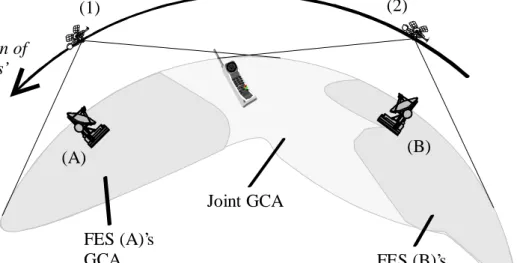
(1) (2) (A) (B) Direction of satellites’ motion FES (B)’s GCA FES (A)’s GCA Joint GCA
Figure 27 Mobile terminal in ocean flip-flopping between FESs A and B
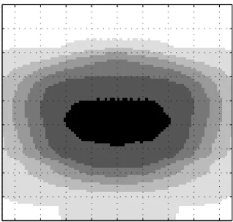
Consider figure 27, with a mobile terminal just outside a GCA but communicating with an FES (A) that is operating independently from any other. If its communications satellite (1) is heading out of range of the mobile, in the direction of the FES (A), then a satellite that could pick up the call rising on the opposite horizon is likely to be too far from the FES (A) to make radio contact with the FES (A). The FES (A) will then have no way to maintain radio contact with the mobile when the current satellite falls below the mobile’s horizon. Simulation of instantaneous coverage from the FES (A) shows the mobile terminal to be outside guaranteed coverage in an area that can only be covered for a certain percentage of the time. Figure 28 shows how the availability of the Globalstar FES at 45°N 0°E falls off outside the solid black GCA. The different levels of grey indicate, moving out from the GCA, coverage for 80%, 60%, 40% and 20% of the time. The white area is never covered by the FES.
Another FES (B), located over the mobile terminal's horizon in the direction from which the new satellite (2) is rising, could communicate through the rising satellite (2) with the mobile terminal. As the satellite (2) rises and gets closer to the mobile terminal it gets further away from the new FES (B) and closer to the original FES (A). At some point the new FES (B) loses radio contact with the satellite but if the two FESs are close enough together then the original FES (A) will be in radio range to continue the call. Evidently the mobile terminal is not inside guaranteed coverage of the second FES (B) either but is instead covered by it for only a proportion of the time. To maintain contact with the FPLMTS network the mobile terminal would continue to "Ping-Pong" between the two FESs, which is quite reasonable during an active call but for a terminal in idle mode to play Ping-Pong by moving its registration from one FES to the other would be an unacceptable waste of resources, as shown in the next chapter. When the simulation of instantaneous coverage was done for joint FES coverage, where coverage is defined by the same conditions of elevation and diversity as before but to either FES, the joint
GCA was found to include the individual FES GCAs and a large area in between them that could not otherwise be covered 100% of the time. Figure 29 shows that for
Globalstar this enlargement of the GCA by joining two (or more) FESs on opposite sides of an ocean is large enough to be able to guarantee coverage of the ocean.
long lat Minimum 1 satellite -40 -30 -20 -10 0 10 20 30 40 90 80 70 60 50 40 30 20 10 long lat Minimum 2 satellites -40 -30 -20 -10 0 10 20 30 40 90 80 70 60 50 40 30 20 10
Figure 28 Probability of linking with an FES at 45°N 0°E outside the GCA through one satellite (left) and through diverse satellites (right)
using the Globalstar constellation
In effect, two FESs have become a single virtual FES, acting in much the same way as a terrestrial base station might use multiple cell antenna sites to cover what is, as far as the network is concerned, the same base station’s coverage area. The difference is that in terrestrial networks the cell sites are reasonably close to each other and connect
hierarchically to the same base station in the radio access network. In satellite networks co-operating FESs will almost certainly be located in different countries, often on different sides of oceans. The UMTS network architecture does not offer another entity in between FESs and LEs to act as co-ordinator between the FESs because of this geographical and international separation - what would it connect to? An LE in only one of the countries?
GCA with Single Coverage
-120 -90 -60 -30 0 30 90
60 30 0
GCA with Double Coverage
-120 -90 -60 -30 0 30 90
60 30 0
Figure 29 Joint GCA of an FES in New York and an FES in Lisbon with (left) γMT ≥20° to a single link and (right) γMT ≥10° and diversity
Neither does the UMTS network architecture offer explicit functions for co-ordination between FESs as this is considered to be just another ingenious way of managing radio and network resources and should be part of the satellite access network’s design, not part of the UMTS standard. It does define functions, interfaces and relationships to support handover, location update and paging for mobile terminals and handle the re-routing of calls between FESs. In the next chapter it will be shown how these are flexible enough to deal with joint GCAs.
5.6.7.
Iridium and ISLs
Iridium is designed to provide elevation angles of 8° or more to mobile terminals. This is the worst case at the equator and therefore must be used as the basis of defining conditions and the link budget for the minimum quality of service. Figure 30 shows the GCA for an FES at 0°N 100°E using only one satellite and no inter-satellite links (ISLs). The GCA is only 260km diameter, which is too small to be of use to a satellite network.
96 98 100 102 104 -4 -2 0 2 4
Iridium
Figure 30 GCA for an Iridium FES at 0°N 100°E assuming ISLs are not available
Because of the low orbits of the satellites, the Iridium constellation connects the
satellites together with a mesh of ISLs. This allows an FES to communicate with mobile terminals by linking into any Iridium satellite and then through ISLs and other satellites to the satellite local to the mobile terminal that handles the final link to the mobile. In this way a single FES could be able to guarantee coverage of the entire globe. A more likely engineering solution would be to reduce the bandwidths of the required FES back haul links and ISLs by using a number of FESs spread around the globe. Each FES would be responsible for a geographic area chosen to match licensing approvals in the same way as GCA shapes would be chosen in any other satellite FPLMTS.
5.7.
Conclusions for Satellites
GCAs are used to promote the FES as a network entity responsible for all mobile terminals registered with it within its geographically fixed coverage area. Coverage areas will be deliberately drawn up to satisfy regulatory and political concerns
[MANDELLA] as far as is technically possible. It has been shown that using GCAs to tile the Earth’s surface with FES coverage does not result in any considerable increase in the number of FESs required to complete a system. The certainty of which FES and core
network operator are involved in providing service in each country could be of
considerable benefit in obtaining licensing agreements to provide service in individual countries.
A slight drawback could be mobile terminals occasionally using the FES’s preferred satellite rather than the closest visible satellite. This might happen if a mobile is within but near the edge of the FES’s GCA. It could happen that the mobile terminal has a better radio path to another satellite being used by another FES but the mobile terminal should continue communications with its current FES unless it begins to lose the link. This ensures that the minimum quality of service is maintained and prevents mobile terminals in the intersection of two GCAs from needlessly Ping-Ponging between the two FESs. It should be remembered that the satellite positions are constantly moving and that each FES will be adapting its communications links to the changing geometry to make the best possible use of the satellites. The stability of the mobile-to-FES links inside the GCA will make inter-FES handovers a very rare occurrence for most mobiles. The use of ISLs and joint GCAs to extend the reach of FESs has been introduced. The operation of these techniques within the UMTS network architecture will be