perating
nstructions
VEGAPULS
68
C
ontents
1 About this document
1.1 Function. . . 4 1.2 Target group. . . 4 1.3 Symbolism used. . . 4 2 For your safety 2.1 Authorised personnel. . . 5 2.2 Appropriate use. . . 5
2.3 Warning about misuse. . . 5
2.4 General safety instructions. . . 5
2.5 Safety approval markings and safety tips . . . 6
2.6 CEconformity. . . 6
2.7 Fulfilling ofNAMURrecommendations. . . 6
2.8 FCCandICconformity(only forUSA/Canada) . 7 2.9 Safety instructions forEx areas . . . 7
2.10 Environmental instructions. . . 7
3 Product description 3.1 Configuration. . . . 8
3.2 Principle of operation. . . 9
3.3 Operation . . . 10
3.4 Packaging,transport and storage. . . 10
4 Mounting 4.1 General instructions. . . 12
4.2 Mounting preparations-Horn antenna . . . 13
4.3 Mounting preparations-Parabolic antenna. . . . 14
4.4 Mounting instructions. . . 16
5 Connecting to power supply 5.1 Preparing the connection. . . 25
5.2 Connection procedure. . . 26
5.3 Wiring plan,double chamber housing. . . 27
5.4 Switch on phase. . . 29
6 Set up with the indicating and adjustment module PLICSCOM 6.1 Short description. . . 31
6.2 Insert indicating and adjustment module. . . 31
6.3 Adjustment system . . . 33
6.4 Setup procedure. . . 34
6.5 Menu schematic. . . 40
6.6 Saving the parameter adjustment data . . . 42
Contents 29262 -EN -080826
7 Setup withPACTware and other adjustment programs
7.1 Connect thePCviaVEGACONNECT. . . 43
7.2 Parameter adjustment withPACTware . . . 44
7.3 Parameter adjustment withAMS™andPDM . . 45
7.4 Saving the parameter adjustment data . . . 45
8 Maintenance and fault rectification 8.1 Maintenance,cleaning. . . 46
8.2 Remove interferences. . . 46
8.3 Exchanging the electronics module. . . 48
8.4 Instrument repair. . . 48 9 Dismounting 9.1 Dismounting steps. . . 50 9.2 Disposal. . . 50 10 Supplement 10.1 Technical data. . . 51 10.2 Dimensions. . . 58
10.3 Industrial property rights. . . 70
10.4 Trademark . . . 70
Supplementary documentation Information:
Supplementary documents appropriate to the ordered version
come with the delivery.You canfind them listed in chapter
"Product description".
Instructions manuals for accessories and replacement parts
Tip:
l 27835-Indicating and adjustment modulePLICSCOM l 25641-Interface adapterVEGACONNECT3
l 32628-Interface adapterVEGACONNECT4 l 31088-Flanges according toDIN-EN-ASME-JIS l 30176-Electronics moduleVEGAPULSseries60 l 31381-Antenna impedance coneVEGAPULS62and68
-EN
1
A
bout this document
1.1 Function
This operating instructions manual provides all the information
you need for mounting,connection and setup as well as
important instructions for maintenance and fault rectification.
Please read this information before putting the instrument into
operation and keep this manual accessible in the immediate
vicinity of the device.
1.2 Target group
This operating instructions manual is directed to trained
personnel.The contents of this manual should be made
available to these personnel and put into practice by them.
1.3 Symbolism used Information,tip,note
This symbol indicates helpful additional information.
Caution:If this warning is ignored,faults or malfunc
-tions can result.
Warning:If this warning is ignored,injury to persons and/or
serious damage to the instrument can result.
Danger:If this warning is ignored,serious injury to persons
and/or destruction of the instrument can result.
Ex applications
This symbol indicates special instructions forEx applications.
l List
The dot set in front indicates a list with no implied sequence.
à
ActionThis arrow indicates a single action.
1 Sequence
Numbers set in front indicate successive steps in a procedure.
1 About this document
29262
-EN
2
F
or your safety
2.1 Authorised personnel
All operations described in this operating instructions manual
must be carried out only by trained specialist personnel
authorised by the plant operator.
During work on and with the device the required personal
protection equipment must always be worn.
2.2 Appropriate use
VEGAPULS68is a sensor for continuous level measurement.
You canfind detailed information on the application range in
chapter"Product description".
Operational reliability is ensured only if the instrument is
properly used according to the specifications in the operating
instructions manual as well as possible supplementary
instructions.
For safety and warranty reasons,any invasive work on the
device beyond that described in the operating instructions manual may be carried out only by personnel authorised by the
manufacturer.Arbitrary conversions or modifications are
explicitly forbidden.
2.3 Warning about misuse
Inappropriate or incorrect use of the instrument can give rise to
application-specific hazards,e.g.vessel overfill or damage to
system components through incorrect mounting or adjustment.
2.4 General safety instructions
This is a high-tech instrument requiring the strict observance of
standard regulations and guidelines.The user must take note
of the safety instructions in this operating instructions manual,
the country-specific installation standards as well as all
prevailing safety regulations and accident prevention rules.
Depending on the model,the emitting frequencies of all radar
sensors are either in theCorKband range.The low
transmitting power lies far below the internationally permitted
limit values.When the instrument used correctly,it presents no
danger to human health.It may be operated without restriction
outside of closed metallic vessels.
-EN
The instrument must only be operated in a technicallyflawless
and reliable condition.The operator is responsible for trouble
-free operation of the instrument.
During the entire duration of use,the user is obliged to
determine the compliance of the required occupational safety measures with the current valid rules and regulations and also
take note of new regulations.
2.5 Safety approval markings and safety tips
The safety approval markings and safety tips on the device
must be observed.
2.6 CEconformity
VEGAPULS68is inCEconformity withEMC(89/336/EWG)
andLVD(73/23/EWG).
Conformity has been judged according to the following
standards:
l EMC:
- EmissionEN61326:1997(classB)
-
SusceptibilityEN61326:1997/A1:1998l R&TTEdirective:I-ETS300-440ExpertOpinionNo. 05-111723,NotifiedBodyNo.0700
l LVD:EN61010-1:2001
2.7 Fulfilling ofNAMURrecommendations
With respect to interference resistance and emitted interfer
-ence,theNAMURrecommendationNE21is fulfilled.
With respect to compatibility,theNAMURrecommendation
NE53is fulfilled.This applies also to the corresponding
indicating and adjustment components.VEGAinstruments are
generally upward and downward compatible.
l Sensor software forDTM VEGAPULS68HART,PAorFF
l DTM VEGAPULS68for adjustment softwarePACTware
l Indicating and adjustment module for sensor software
The parameter adjustment of the basic sensor functions is
independent of the software version.The range of available
functions depends on the respective software version of the
individual components.
The software version ofVEGAPULS68can be determined as
follows: 2 For your safety 29262 -EN -080826
l viaPACTware
l on the type label of the electronics
l via the indicating and adjustment module
You can view all software histories on our website www.vega.
com.Make use of this advantage and get registered for update
information via e-mail.
2.8 FCCandICconformity (only forUSA/Canada)
VEGAPULSsensors with all antenna versions areFCCandIC
approved:
l FCC ID:O6QPULS68
l IC:3892A-PS68
Modifications not expressly approved byVEGAwill lead to
expiry of the operating licence according toFCC.
VEGAPULS68is in conformity with part15of theFCC
regulations.Take note of the respective operating regulations:
l The instrument must not cause any interfering emissions
l This device must accept any interference received,
including interference that may cause undesired operation.
2.9 Safety instructions forEx areas
Please note theEx-specific safety information for installation
and operation inEx areas.These safety instructions are part of
the operating instructions manual and come with theEx
-approved instruments.
2.10 Environmental instructions
Protection of the environment is one of our most important
duties.That is why we have introduced an environment
management system with the goal of continuously improving
company environmental protection.The environment man
-agement system is certified according toDIN EN ISO14001.
Please help us fulfil this obligation by observing the environ
-mental instructions in this manual:
l Chapter"Packaging,transport and storage"
l Chapter"Disposal"
-EN
3
P
roduct description
3.1 Configuration
The scope of delivery encompasses:
l VEGAPULS68radar sensor
l Documentation
- this operating instructions manual
- SafetyManual31338"VEGAPULSseries60
-4…20mA/HART"
- Operating instructions manual-27835"Indicating and
adjustment modulePLICSCOM"(optional)
- Ex-specific"Safety instructions"(withEx-versions)
- if necessary,further certificates
VEGAPULS68consists of the following components:
l Horn or parabolic antenna
l processfitting(depending on the versionflange or thread)
l Each optionally available with swivelling holder(only with
flange),rinsing air connection,reflux valve
l Housing with electronics
l Housing cover,optionally available with indicating and
adjustment modulePLICSCOM
The components are available in different versions.
Scope of delivery Components 3 Product description 29262 -EN -080826
1
2
3
4
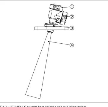
Fig.1:VEGAPULS68with horn antenna and swivelling holder
1 Housing cover with integratedPLICSCOM(optional)
2 Housing with electronics
3 Swivelling holder withflange
4 Horn antenna
3.2 Principle of operation
VEGAPULS68is a radar sensor inK-band technology for
continuous level measurement in solids.
Aversion ofVEGAPULS68is available for each area of
application:
l The version with horn antenna is particularly suitable for
measurement of virtually all bulk solids in small silos and
vessels.
l The version with parabolic antenna is particularly suitable
for large silos and vessels with up to70m(76yd)
measuring distance and for measurement of solids with low
dielectric constant.
VEGAPULS68is also suitable for applications in liquids.
The antenna of the radar sensor emits short radar pulses with
a duration of approx.1ns.These pulses are reflected by the
product and received by the antenna as echoes.The running
time of the radar pulses from emission to reception is
Area of application Functional principle -EN -080826
proportional to the distance and hence to the level.The
determined level is converted into an appropriate output signal
and outputted as measured value.
Four-wire electronics with separate power supply.
The supply voltage range can differ depending on the
instrument version.
Data for power supply is specified in chapter"Technical data".
Measured value transmission is carried out via the4…20mA/
HARToutput separate from power supply.
The backlight of the indicating and adjustment module is
powered by the sensor.The prerequisite for this is a supply
voltage at a certain level.The exact voltage specifications are
stated in chapter"Technical data". 3.3 Operation
VEGAPULS68can be adjusted with different adjustment
media:
l with indicating and adjustment module
l with the suitableVEGA DTMin conjunction with an
adjustment software according to theFDT/DTMstandard,
e.g.PACTware andPC
l with manufacturer-specific adjustment programsAMS™or
PDM
l With aHARThandheld
The entered parameters are generally saved inVEGAPULS
68,optionally also in the indicating and adjustment module or
inPACTware.
3.4 Packaging,transport and storage
Your instrument was protected by packaging during transport.
Its capacity to handle normal loads during transport is assured
by a test according toDIN EN24180.
The packaging of standard instruments consists of environ
-ment-friendly,recyclable cardboard.For special versions,PE
foam orPEfoil is also used.Dispose of the packaging material
via specialised recycling companies.
Transport must be carried out under consideration of the notes
on the transport packaging.Nonobservance of these instruc
-tions can cause damage to the device.
Voltage supply Packaging Transport 3 Product description 29262 -EN -080826
The delivery must be checked for completeness and possible
transit damage immediately at receipt.Ascertained transit
damage or concealed defects must be appropriately dealt with.
Up to the time of installation,the packages must be left closed
and stored according to the orientation and storage markings
on the outside.
Unless otherwise indicated,the packages must be stored only
under the following conditions:
l Not in the open
l Dry and dust free
l Not exposed to corrosive media
l Protected against solar radiation
l Avoiding mechanical shock and vibration
l Storage and transport temperature see"Supplement
-Technical data-Ambient conditions"
l Relative humidity20…85%
Transport inspection
Storage
Storage and transport temperature
-EN
4
M
ounting
4.1 General instructions
Select an installation position you can easily reach for
mounting and connecting as well as later retrofitting of an
indicating and adjustment module.The housing can be rotated
by330°without the use of any tools.You can also install the
indicating and adjustment module in four different positions
(each displaced by90°).
Warning:
With threaded versions,the housing must not be used to screw
in the instrument!Applying tightening forces on the housing
can damage its internal parts.
Use the recommended cables(see chapter"Connecting to
power supply")and tighten the cable gland.
You can give your instrument additional protection against
moisture penetration by leading the connection cable down
-ward in front of the cable entry.Rain and condensation water
can thus drain off.This applies mainly to outdoor mounting as
well as installation in areas where high humidity is expected(e.
g.through cleaning processes)or on cooled or heated
vessels.
Fig.2:Measures against moisture penetration
The reference plane for the measuring range of the sensors is
the lower edge of theflange or the seal surface of the thread.
Mounting position Screwing in Moisture Measuring range 4 Mounting 29262 -EN -080826
1 2 3
100%
0% 4
Fig.3:Measuring range(operating range),max.measuring distance and
reference plane
1 full
2 empty(max.measuring distance)
3 Measuring range
4 Reference plane
Information:
If the medium reaches the antenna,buildup can form on it and
cause faulty measurements later on.
Make sure that all parts of the instrument in contact with the
measured product,especially the sensor element,process
seal and processfitting,are suitable for the existing process
conditions such as process pressure,process temperature as
well as the chemical properties of the medium.
You canfind the specifications in chapter"Technical data"in
the or on the type label.
4.2 Mounting preparations-Horn antenna Information:
This information applies only to special versions!
VEGAPULS68is also available in versions where the antenna
has a bigger diameter than the processfitting(thread,flange).
The antenna must therefore be disconnected from the process
fitting before mounting.Proceed as follows:
1 Loosen the hexagon screws(3)on the antenna socket with
anAllan key(size3)
Suitability for process conditions
-EN
2 Remove the antenna(4)
Note:
The plastic conemust not be pulled out of the antenna socket.
3 Insert the antenna from below into the vessel socket and
secure it against falling off
4 Retighten the antenna with hexagon screws to the antenna
socket;torque max.10Nm(7.5lbf ft)
Note:
VEGAPULS68with rinsing air connection or antenna
extension is provided with a notch on the antenna socket.This
notch must correspond to the marking on the hexagon of the
processfitting(the marking specifies the position of the
polarisation level of the radar signal).
3 4 1
2
Fig.4:Dismounting horn antenna
1 Marking
2 Notch
3 Hexagon screws on the antenna socket
4 Antenna
4.3 Mounting preparations-Parabolic antenna Information:
This information applies only to special versions!
VEGAPULS68is also available in versions where the antenna
has a diameter larger than the processfitting(thread,flange).
With such versions the antenna must be disconnected from
the processfitting before mounting.Proceed as follows:
4 Mounting 29262 -EN -080826
1 ClampVEGAPULS68with theflange,e.g.in a bench vice
2 Hold the connection piece(3)with a wrenchSW22on the
flattenings
3 Unscrew the locknut(2)withSW36against the antenna
4 Loosen compression nut(1)with a screwdriverSW41
completely in the direction of the antenna
5 Remove the parabolic antenna(4)axially
6 Mount sensorflange to the adapterflange and clamp it
7 Check,if theO-ring seal is available on the adapter and if it
is not damaged.
Note:
AdamagedO-ring seal must be replaced:FKM(Viton)article
no.2.28248,FFKM(Kalrez6375)article no.2.27351
8 Remount the parabolic antenna(4)
9 Tighten compression nut(3)withSW41,torque max.
50Nm
10 Tighten locknut(2)withSW36,torque max.40Nm.
Note:
Take note forVEGAPULS68with rinsing air connection that
the holes in the antenna and in the processfitting correspond.
This ensures a sufficient airflow(the air is led through the
holes to the feed system.Arinsing of the parabolic antenna in
total is not intended).
-EN
1
2 3 4
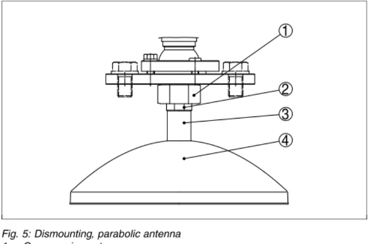
Fig.5:Dismounting,parabolic antenna
1 Compression nut
2 Locknut
3 Connection piece
4 Parabolic antenna
4.4 Mounting instructions
The illustrations with the following mounting instructions show
aVEGAPULS68with horn antenna.The mounting instructions
apply analogously also to the version with parabolic antenna.
Mount the sensor at least200mm(7.874in)away from the
vessel wall.
1 2
Fig.6:Mounting position
1 Reference plane
Horn and parabolic an -tenna Mounting position 4 Mounting 29262 -EN -080826
If you cannot keep this distance you should carry out a false
echo storage before setup.This applies mainly if buildup on
the vessel wall is expected.In this case,we recommend
repeating a false echo storage later with existing buildup.
To measure as much of the vessel volume as possible,the
sensor should be aligned so that the measuring beam reaches
the lowest level in the vessel.In a cylindrical silo with conical
outlet,the easiest way is to mount the instrument in the center
of the silo.
Fig.7:Orientation
If mounting in the center of the silo is not possible,the sensor
can be directed to the vessel center by means of an optional
swivelling holder.The following description gives an overview
on the determination of the necessary angle of inclination.
Orientation
-EN
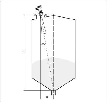
d
a
α
Fig.8:Proposal for installation after orientationVEGAPULS68
The angle of inclination depends on the vessel dimensions.It
can be checked easily on the sensor with a suitable level or
air-lever.The following chart states the distance"a"between
installation position and vessel center depending on the
measuring distance for an angle of inclination of2°…10°.
Distance d (m) 2° 4° 6° 8° 10° 2 0.1 0.1 0.2 0.3 0.4 4 0.1 0.3 0.4 0.6 0.7 6 0.2 0.4 0.6 0.8 1.1 8 0.3 0.6 0.8 1.1 1.4 10 0.3 0.7 1.1 1.4 1.8 15 0.5 1.0 1.6 2.1 2.6 20 0.7 1.4 2.1 2.8 3.5 25 0.9 1.7 2.6 3.5 4.4 30 1.0 2.1 3.2 4.2 5.3 35 1.2 2.4 3.7 4.9 6.2 40 1.4 2.8 4.2 5.6 7.1 45 1.6 3.1 4.7 6.3 7.9 50 1.7 3.5 5.3 7 8.8 4 Mounting 29262 -EN -080826
Distance d (m) 2° 4° 6° 8° 10° 55 1.9 3.8 5.8 7.7 9.7 60 2.1 4.2 6.3 8.4 10.6 65 2.3 4.5 6.8 9.1 11.5 70 2.4 4.9 7.4 9.8 12.3 Example:
In a vessel with20m height,the installation position of the
sensor is1.4m from the vessel center.
The necessary angle of inclination of4°can be read out from
this chart.
Proceed as follows to adjust the angle of inclination with the
swivelling holder:
1 Loosen terminal screw of the swivelling holder with a fork
spannerSW13
2 Direct the sensor,check angle of inclination
Information:
The max.angle of inclination of the swivelling holder is approx.
15°
3 Tighten the terminal screw,torque max.20Nm.
Information:
The hexagon screws must not be loosened.
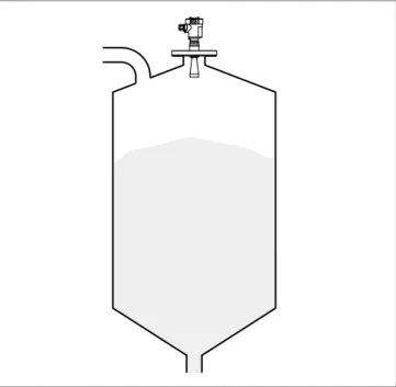
Mounting should not be too close to the inflowing material as
the microwave signal will be interferred.The optimum
mounting position is on the opposite of thefilling.To avoid
strong pollution,the distance to thefilter or dust extraction
must be as big as possible.
Inflowing medium
-EN
Fig.9:Inflowing medium
Socket pieces should be dimensioned such that the antenna
end protrudes at least10mm(0.4in)out of the socket.
10 mm
>
Fig.10:Recommended socket mounting
If the reflective properties of the medium are good,you can
mountVEGAPULS68on sockets which are higher than the
length of the antenna.You willfind recommended values for
socket heights in the following illustration.The socket end
should be smooth and burr-free,if possible also rounded.After
installation you must carry out a false echo storage.
Socket 4 Mounting 29262 -EN -080826
d hmax. d 1½" 50 mm/2" 80 mm/3" 100 mm/4" 150 mm/6" 200 mm 250 mm 300 mm 500 mm 800 mm hmax.
Fig.11:Deviating socket dimensions
Tip:
VEGAPULS68is optionally also available with antenna
extension.Hence the antenna length can be selected such
that the antenna end protrudes10mm(0.4in)out of the
socket.
The silo walls of multiple chamber silos are often made of
profile walls,such as e.g.profile sheeting,to ensure the
required stability.If the radar sensor is mounted very close to a
heavily structured vessel wall,considerable false reflections
can be generated.Hence the sensor should be mounted at a
large distance from the separating wall.The optimal mounting
position is on the outer wall of the silo with the sensor directed
towards the emptying aperture in the silo center.
Mounting in multiple channel silo -EN -080826
Fig.12:Installation ofVEGAPULS68in multiple chamber silos
Fig.13:Orientation ofVEGAPULS68for emptying in the silo center
Silo installations such as e.g.ladders,level switches,struts,
and also structured vessel walls,can cause false echoes that
get superimposed on the useful echo.The mounting location
Vessel installations 4 Mounting 29262 -EN -080826
of the radar sensor should be a place where no installations
cross the microwave signals.Make sure when planning your
measurement loop that the radar signals have a"clear view"to
the product.
In case of existing vessel installations,a false echo storage
should be carried out during setup.
If large vessel installations such as struts or supports cause
false echoes,these can be attenuated through supplementary
measures.Small,inclined sheet metal baffles above the
installations scatter the radar signals and prevent direct
interfering reflections.
Fig.14:Cover smooth profiles with deflectors
To avoid strong buildup and dust in the antenna system,the
sensor should not be mounted directly at the dust extraction of
the vessel.
Tip:
In case of extreme dust in the antenna system,VEGAPULS68
is available with purging connection e.g.for air.The air is
distributed via channels in the antenna system and keeps is
virtually clean from dust.
Fig.15:Purging air connection with horn antenna
Air purging
-EN
Fig.16:Purging air connection with parabolic antenna
In practice it was shown that a pressure of approx.0.2…1bar
is enough to provide a sufficient airflow(see diaphragm in
chapter"Technical data").
Large material heaps are detected with several sensors,which
can be mounted on e.g.traverse cranes.For this type of
application,it is best to orient the sensor toward the solid
surface.Amutual infuence of the sensor is not possible.
Fig.17:Radar sensors on traverse crane
Information:
Keep in mind that for these applications,the sensors are
designed for relatively slow level changes.When using
VEGAPULS68on a movable bracket,the max.measuring rate
must be observed(see chapter"Technical data").
Material heaps 4 Mounting 29262 -EN -080826
5
C
onnecting to power supply
5.1 Preparing the connection
Always keep in mind the following safety instructions:
l Connect only in the complete absence of line voltage
l If overvoltage surges are expected,overvoltage arresters
should be installed.
Tip:
We recommend usingVEGAovervoltage arrestersB63-48
and ÜSB62-36G.X.
In hazardous areas you should take note of the appropriate
regulations,conformity and type approval certificates of the
sensors and power supply units.
Supply voltage and current output are carried on separate two
-wire connection cables if reliable separation is required.The
supply voltage range can differ depending on the instrument
version.
Data for power supply is specified in chapter"Technical data".
The standard version can be operated with an earth
-connected current output,theExd version must be operated
with afloating output.
This instrument is designed in protection classI.To maintain
this protection class,it is absolutely necessary that the ground
conductor be connected to the internal ground terminal.Take
note of the general installation regulations.
As a rule,connect the instrument to vessel ground(potential
euqalisation)or in case of plastic vessels to the next ground
potential.For this purpose there is a ground terminal on the
side of the instrument housing.
For power supply,an approved installation cable withPE
conductor is necessary.
The4…20mAcurrent output is connected with standard two
-wire cable without screen.If electromagnetic interference is
expected which is above the test values ofEN61326for
industrial areas,screened cable should be used.
Note safety instructions
Take note of safety instruc -tions forEx ap -plications
Select power supply
Selecting connection cable -EN -080826
Use cable with round cross-section.Acable outer diameter of
5…9mm(0.2…0.35in)ensures the seal effect of the cable
gland.If you are using cable with other diameter or cross
-section,you have to exchange the seal or use a suitable cable
gland.
If screened cable is necessary,connect the cable screen on
both ends to ground potential.In the sensor,the screen must
be connected directly to the internal ground terminal.The
ground terminal on the outside of the housing must be
connected to the potential equalisation(low impedance).
If potential equalisation currents are expected,the connection
on the processing side must be made via a ceramic capacitor
(e.g.1nF,1500V).The low frequency potential equalisation
currents are thus suppressed,but the protective effect against
high frequency interference signals remains.
Take note of the corresponding installation regulations forEx
applications.In particular,make sure that no potential equal
-isation currentsflow over the cable screen.In case of
grounding on both sides this can be achieved by the use of a
capacitor or a separate potential equalisation.
With theExd version,the minus side of the signal output is
galvanically connected to ground via protective diodes.When
connecting the instrument to a groundedPLC,equalising
currents canflow in case of potential differences which can
cause malfunctions.Make sure that there is sufficient potential
equalisation from the system side or realise the connection via
switching amplifier.
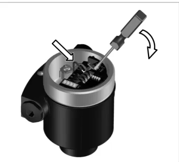
5.2 Connection procedure
Proceed as follows:
1 Unscrew the housing cover
2 If an indicating and adjustment module is installed,remove
it by turning it slightly to the left.
3 Loosen compression nut of the cable entry
4 Remove approx.10cm(4in)of the cable mantle,strip
approx.1cm(0.4in)insulation from the ends of the
individual wires
5 Insert the cable through the cable gland into the sensor
6 Lift the opening levers of the terminals with a screwdriver
(see following illustration)
Cable screening and grounding
Installation with Ex applications
5 Connecting to power supply
29262
-EN
7 Insert the wire ends into the open terminals according to the wiring plan
Fig.18:Connection steps6and7
8 Press down the opening levers of the terminals,you will
hear the terminal spring closing
9 Check the hold of the wires in the terminals by lightly
pulling on them
10 Connect the screen to the internal ground terminal,connect
the outer ground terminal with potential equalisation
11 Tighten the compression nut of the cable entry.The seal
ring must completely encircle the cable
12 Screw the housing cover on
The electrical connection isfinished.
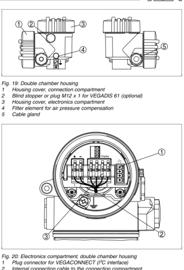
5.3 Wiring plan,double chamber housing
The following illustrations apply to the non-Ex as well as to the
Ex-d version.
-EN
1 2 3
4 5
Fig.19:Double chamber housing
1 Housing cover,connection compartment
2 Blind stopper or plugM12x1forVEGADIS61(optional)
3 Housing cover,electronics compartment
4 Filter element for air pressure compensation
5 Cable gland 1 3 2 Display 1 2 5 6 7 8 I²C
Fig.20:Electronics compartment,double chamber housing
1 Plug connector forVEGACONNECT(I²Cinterface)
2 Internal connection cable to the connection compartment
3 Terminals forVEGADIS61
Housing overview
Electronics compart -ment
5 Connecting to power supply
29262
-EN
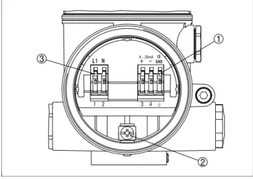
3 1 2 3 4 1 2 L 1 N 4... 20mAGNDI S
Fig.21:Connection compartment,double chamber housing
1 Spring-loaded terminals for signal output
2 Ground terminal for connection of the ground conductor and screen
3 Spring-loaded terminals for voltage supply
Information:
Keep in mind that the indicating and adjustment module must
only be used in the electronics compartment.
4 ... 20 mA PE / L / N L1 N GND 1 2 1 2 3 4 4...20mA IS
Fig.22:Wiring plan,double chamber housing
1 Voltage supply
2 Signal output
5.4 Switch on phase
After connectingVEGAPULS68to power supply or after a
voltage recurrence,the instrument carries out a self-check for
approx.30seconds: Connection compart -ment Wiring plan Switch on phase -EN -080826
l Internal check of the electronics
l Indication of the instrument type,thefirmware as well as
the sensorTAGs(sensor designation)
l Output signal jumps briefly(approx.10seconds)to the set
fault current
Then the corresponding current is outputted to the cable(the
value corresponds to the actual level as well as the settings
already carried out,e.g.factory setting).
5 Connecting to power supply
29262
-EN
6
S
et up with the indicating and
adjustment module
PLICSCOM
6.1 Short description
The indicating and adjustment module is used for measured
value display,adjustment and diagnosis.It can be mounted in
the following housing versions and instruments:
l All sensors of the plics®instrument family,in the single as
well as in the double chamber housing(optionally in the
electronics or connection compartment)
l External indicating and adjustment unitVEGADIS61
From a hardware version…-01or higher of the indicating and
adjustment module as well as of the corresponding sensor,an
integrated backlight can be switched on via the adjustment
menu.The hardware version is stated on the type label of the
indicating and adjustment module or the sensor electronics.
Note:
You canfind detailed information on the adjustment in the
operating instructions manual"Indicating and adjustment
module".
6.2 Insert indicating and adjustment module
The indicating and adjustment module can be inserted into the
sensor and removed again at any time.It is not necessary to
interrupt the power supply.
Proceed as follows:
1 Unscrew the housing cover
2 Place the indicating and adjustment module in the desired
position on the electronics(you can choose any one of four
different positions-each displaced by90°)
3 Press the indicating and adjustment module onto the
electronics and turn it to the right until it snaps in.
4 Screw housing cover with inspection window tightly back
on
Removal is carried out in reverse order.
The indicating and adjustment module is powered by the
sensor,an additional connection is not necessary.
Function/Configuration
Mount/Dismount indicat -ing and adjustment module
-EN
Fig.23:Installation of the indicating and adjustment module Note:
If you intend to retrofit the instrument with an indicating and
adjustment module for continuous measured value indication,
a higher cover with an inspection glass is required.
6 Set up with the indicating and adjustment modulePLICSCOM
29262
-EN
6.3 Adjustment system
1.1
2
3 1
Fig.24:Indicating and adjustment elements
1 LCdisplay
2 Indication of the menu item number
3 Adjustment keys
l [OK]key:
- Move to the menu overview
- Confirm selected menu - Edit parameter
-
Save value l [->]key to select: - menu change - list entry-
Select editing positionl [+]key:
-
Change value of the parameterl [ESC]key:
- interrupt input
-
jump to the next higher menuThe sensor is adjusted via the four keys of the indicating and
adjustment module.TheLCdisplay indicates the individual
menu items.The functions of the individual keys are shown in
the above illustration.Approx.10minutes after the last
pressing of a key,an automatic reset to measured value
indication is triggered.Any values not confirmed with[OK]will
not be saved. Key functions Adjustment system -EN -080826
6.4 Setup procedure
InHART-Multidrop mode(several sensors on one input)the
address must be set before continuing with the parameter
adjustment.You willfind a detailed description in the operating
instructions manual"Indicating and adjustment module"or in
the online help ofPACTware orDTM.
HARTmode
Standard
Address0
AsVEGAPULS68is a distance measuring instrument,the
distance from the sensor to the product surface is measured.
To have the real product level displayed,an allocation of the
measured distance to the percentage height must be made.To
carry out this adjustment,the distance is entered with full and
empty vessel.If these values are not known,an adjustment
with the distance values,e.g.10%and90%is also possible.
Starting point for these distance specifications is always the
seal surface of the thread orflange.With these settings,the
real level is calculated.Furthermore the operating range of the
sensor is limited from maximum to the required range.
The real product level during this adjustment is not important,
because the min./max.adjustment is always carried out
without changing the product level.These settings can be
made ahead of time without the instrument having to be
installed.
In the main menu item"Basic adjustment",the individual
submenu items should be selected one after the other and
provided with the correct parameter values.
Start your parameter adjustment with the following menu items
of the basic adjustment:
Proceed as follows:
1 Move from the measured value display to the main menu
by pushing[OK]. ▶Basic adjustment Display Diagnostics Service Info
Address settingHART -Multidrop
Parameter adjustment
Carrying out min.ad -justment
6 Set up with the indicating and adjustment modulePLICSCOM
29262
-EN
2 Select the menu item"Basic adjustment"with[->]and
confirm with[OK].Now the menu item"Min.adjustment"is
displayed. Min.adjustment 0.00% = 5.000m(d) 4.000m(d)
3 Prepare the%value for editing with[OK]and set the
cursor to the requested position with[->].Set the
requested percentage value with[+]and save with[OK].
The cursor jumps now to the distance value.
4 Enter the suitable distance value in m for the empty vessel
(e.g.distance from the sensor to the vessel bottom)
corresponding to the percentage value.
5 Save the settings with[OK]and move to"Max.adjustment"
with[->]. Proceed as follows: Max.adjustment 100.00% = 1.000m(d) 2.000m(d)
1 Prepare the%value for editing with[OK]and set the
cursor to the requested position with[->].Set the
requested percentage value with[+]and save with[OK].
The cursor jumps now to the distance value.
2 Enter the appropriate distance value in m(corresponding
to the percentage value)for the full vessel.Keep in mind
that the max.level must lie below the dead band.
3 Save the settings with[OK]and move to"Medium
selection"with[->].
Each product has different reflective properties.In solids,
these are dust generation,material cones and additional
echoes caused by the vessel wall.Due to the medium
selection,the sensor is adapted in an optimum way to the
product and the accuracy,particularly for products with bad
reflective properties,is increased considerably.
Medium
Solid
Carrying out max.ad -justment Medium selection -EN -080826
With solids,you can also choose between"Powder/Dust", "Granular/Pellets"or"Ballast/Pebbels".
In liquids,fluctuating surfaces and foam generation are further
interfering factors.To adapt the sensor to the different
conditions,a general selection is made in this menu item,i.e.
"Solid"or"Liquid".
Enter the requested parameter via the appropriate keys,save
your settings and jump to the next menu item with the[->]key.
Apart from the medium,the vessel shape can also influence
the measurement.To adapt the sensor to these measuring
conditions,this menu item offers different options depending
on whether liquid or solid is selected.With"Solid"these are
"Silo"or"Bunker",with"Liquid","Storage tank","Stilling tube",
"Open vessel"or"Stirred vessel".
Vessel form
Silo
Enter the requested parameter via the appropriate keys,save
your settings and jump to the next menu item with the[->]key.
Alinearization is necessary for all vessels in which the vessel
volume does not increase linearly with the level-e.g.with a
cylindrical or spherical tank-and the indication or output of the
volume is required.Corresponding linearization curves are
preprogrammed for these vessels.They represent the
correlation between the level percentage and vessel volume.
By activating the appropriate curve,the volume percentage of
the vessel is displayed correctly.If the volume should not be
displayed in percent but e.g.in l or kg,a scaling can be also
set in the menu item"Display".
Linearisation curve
linear
Enter the requested parameter via the appropriate keys,save
your settings and jump to the next menu item with the[->]key.
Vessel form
Linearisation curve
6 Set up with the indicating and adjustment modulePLICSCOM
29262
-EN
High sockets or vessel installations,such as e.g.struts or
agitators as well as buildup and weld joints on the vessel walls
cause interfering reflections which can impair the measure
-ment.Afalse echo storage detects and marks these false
echoes,so that they are no longer taken into account for the
level measurement.Afalse echo memory should be created
with empty vessel so that all potential interfering reflections will
be detected.
Gating out of false signals
Change now?
Proceed as follows:
1 Move from the measured value display to the main menu
by pushing[OK].
2 Select the menu item"Service"with[->]and confirm with
[OK].Now the menu item"False signal suppression"is
displayed.
3 Confirm"False signal suppression-Change now"with
[OK]and select in the below menu"Create new".Enter the
actual distance from the sensor to the product surface.All
false signals in this area are detected by the sensor and
saved after confirming with[OK].
Note:
Check the distance to the product surface,because if an
incorrect(too large)value is entered,the existing level will be
saved as false signal.Thefilling level would then no longer be
detectable in this area.
The menu item"Extended setting"offers the possibility to
optimiseVEGAPULS68for applications in which the level
changes very quickly.For this reason,select the function
"Quick level change>1m/min.".
Extended setting
quick level change>1m/min. Gating out of false sig
-nals
Extended setting/Quick
level change
-EN
Note:
Since with the function"Quick level change>1m/min."the
generation of an average value of the signal processing is
considerably reduced,false reflections by agitators or vessel
installations can cause measured valuefluctuations.Afalse
echo memory is thus recommended.
This function enables reading out parameter adjustment data
as well as writing parameter adjustment data into the sensor
via the indicating and adjustment module.Adescription of the
function is available in the operating instructions manual
"Indicating and adjustment module".
The following data are read out or written with this function:
l Measured value presentation
l Adjustment
l Medium
l Inner diameter of the standpipe(with standpipe versions)
l Vessel form l Damping l Linearisation curve l Sensor-TAG l Displayed value l Display unit l Scaling l Current output l Unit of measurement l Language
The following safety-relevant data arenotread out or written:
l HARTmode
l PIN
l SIL
Copy sensor data
Copy sensor data?
Basic adjustment
If the"Reset"is carried out,the sensor resets the values of the
following functions to the reset values(see chart):1)
1) Sensor-specific basic adjustment.
Copy sensor data
Reset
6 Set up with the indicating and adjustment modulePLICSCOM
29262
-EN
Function Reset value Max.adjustment 0m(d)
Min.adjustment 15m(d) (VEGAPULS67) 70m(d) (VEGAPULS68)
Medium Solid
Vessel form not known
Damping 0s
Linearisation linear
Sensor-TAG Sensor
Displayed value Distance
Extended settings None
Current output-characteristics 4…20mA Current output-max.current 20mA Current output-min.current 4mA Current output-failure <3.6mA Unit of measurement m(d)
The values of the following functions arenotreset to the reset
values(see chart)with"Reset":
Function Reset value
Lighting no reset
Language no reset
SIL no reset
HARTmode no reset
Factory setting
Like basic adjustment,furthermore special parameters are
reset to default values.2)
Pointer
The min.and max.distance values are reset to the actual
value.
Additional adjustment and diagnosis options such as e.g.
scaling,simulation or trend curve presentation are shown in
the following menu schematic.You willfind a detailed
description of these menu items in the operating instructions
manual"Indicating and adjustment module".
2) Special parameters are parameters which are set customer-specifically on
Optional settings
-EN
6.5 Menu schematic Information:
Depending on the version and application,the light-coloured
menu windows are not always available or offer nor selection
possibility. Basic adjustment 1 ▶Basic adjustment Display Diagnostics Service Info 1.1 Min.adjustment 0.00% = 30.000m(d) 0.665m(d) 1.2 Max.adjustment 100.00% = 0.000m(d) 0.665m(d) 1.3 Medium Bulk solid▼ not known▼ 1.4 Vessel form not known▼ 1.5 Damping 0s 1.6 Linearisation curve linear 1.7 Sensor-TAG Sensor Display 2 Basic adjustment ▶Display Diagnostics Service Info 2.1 Displayed value Scaled 2.2 Display unit Volume▼ l▼ 2.3 Scaling 0% =0.0l 100% =100.0l 2.4 Lighting Switched off▼ Diagnostics 3 Basic adjustment Display ▶Diagnostics Service Info
6 Set up with the indicating and adjustment modulePLICSCOM
29262
-EN
Pointer Distance min.:0.234m(d) Distance max.:5.385m(d) 3.2 Meas.reliability 15dB Sensor status OK 3.3 Curve selection Echo curve▼ 3.4 Echo curve
Presentation of the echo curve Service 4 Basic adjustment Display Diagnostics ▶Service Info 4.1 Gating out of false signals
Change now? 4.2 Extended setting None▼ 4.3 Current output Output mode:4-20mA▼ Fail.mode:<3.6mA▼ min.current:4mA▼ max.current:20mA▼ 4.4 Simulation Start simulation 4.5 Reset Select reset? 4.7 Unit of measurement m(d)▼ 4.8 Language Deutsch▼ 4.8 HARTmode Standard Address0 4.9 Copy sensor data
Copy sensor data?
4.10 PIN Enable? Info 5 Basic adjustment Display Diagnostics Service ▶Info 5.1 Sensor type Serial number 12345678 5.2 Date of manufacture 4.August2008 Software version 3.50 5.3 Last change usingPC
4.August2008 5.4 Sensor characteristics Display now? -EN -080826
6.6 Saving the parameter adjustment data
It is recommended noting the adjusted data,e.g.in this
operating instructions manual and archive them afterwards.
They are hence available for multiple use or service purposes.
IfVEGAPULS68is equipped with an indicating and adjust
-ment module,the most important data can be read out of the
sensor into indicating and adjustment module.The procedure
is described in the operating instructions manual"Indicating
and adjustment module"in the menu item"Copy sensor data".
The data remain there permanently even if the sensor power
supply fails.
If it is necessary to exchange the sensor,the indicating and
adjustment module is inserted into the replacement instrument and the data are written into the sensor under the menu item
"Copy sensor data".
6 Set up with the indicating and adjustment modulePLICSCOM
29262
-EN
7
S
etup with
PACT
ware and other
adjustment programs
7.1 Connect thePCviaVEGACONNECT
3 1
2
Fig.25:Connection of thePCviaVEGACONNECTdirectly to the sensor
1 USBcable to thePC
2 VEGACONNECT 3 Sensor 1 2 3 4 OPEN TWIST USB LOCK
Fig.26:Connection viaI²Cconnection cable
1 I²Cbus(com.)interface on the sensor
2 I²Cconnection cable ofVEGACONNECT
3 VEGACONNECT
4 USBcable to thePC
Internal connection via
I²Cinterface
External connection via
I²Cinterface
-EN
Necessary components:
l VEGAPULS68
l PCwithPACTware and suitableVEGA DTM
l VEGACONNECT
l Power supply unit or processing system
1
5 2 4
3 OPEN
TWIST USB
LOCK
Fig.27:Connecting thePCviaHARTto the signal cable
1 VEGAPULS68
2 HARTresistor250Ω (optional depending on processing)
3 Connection cable with2mm pins and terminals
4 Processing system/PLC/Voltage supply
Necessary components:
l VEGAPULS68
l PCwithPACTware and suitableVEGA DTM
l VEGACONNECT4
l HARTresistor approx.250Ω
l Power supply unit or processing system
Note:
With power supply units with integratedHARTresistance
(internal resistance approx.250Ω),an additional external
resistance is not necessary.This applies,e.g.to theVEGA
instrumentsVEGATRENN149A,VEGADIS371,VEGAMET
381).Also usualEx separators are most of the time equipped
with a sufficient current limitation resistor.In such cases,
VEGACONNECT4can be connected parallel to the4…20mA
cable.
7.2 Parameter adjustment withPACTware
Further setup steps are described in the operating instructions
manual"DTM Collection/PACTware"attached to eachCDand
Connection viaHART
7 Setup withPACTware and other adjustment programs
29262
-EN
which can also be downloaded from our homepage.Adetailed
description is available in the online help ofPACTware and the
VEGA DTMs.
Note:
Keep in mind that for setup ofVEGAPULS68,DTM-Collection
in the actual version must be used.
All currently availableVEGA DTMs are provided in theDTM
Collection onCDand can be obtained from the responsible
VEGAagency for a token fee.ThisCDincludes also the up-to
-datePACTware version.The basic version of thisDTM
Collection incl.PACTware is also available as a free-of-charge
download from theInternet.
Go via www.vega.com and"Downloads"to the item"S oft-ware".
7.3 Parameter adjustment withAMS™andPDM
ForVEGAsensors,instrument descriptions for the adjustment
programsAMS™andPDMare available asDDorEDD.The
instrument descriptions are already implemented in the current
versions ofAMS™andPDM.For older versions ofAMS™and
PDM,a free-of-charge download is available viaInternet.
Go via www.vega.com and"Downloads"to the item"S oft-ware".
7.4 Saving the parameter adjustment data
It is recommended to document or save the parameter
adjustment data.They are hence available for multiple use or
service purposes.
TheVEGA DTM Collection andPACTware in the licensed,
professional version provide suitable tools for systematic
project documentation and storage.
-EN
8
M
aintenance and fault recti
fi
cation
8.1 Maintenance,cleaning
When used in the correct way,no special maintenance is
required in normal operation.
In some applications,buildup on the antenna system can
influence the measuring result.Depending on the sensor and
application,make arrangements to avoid strong pollution of the
antenna system.If necessary,clean the antenna system in
certain intervals.
8.2 Remove interferences
The operator of the system is responsible for taken suitable
measures to remove interferences.
Amaximum of reliability is ensured.Nevertheless,faults can
occur during operation.These may be caused by the following,
e.g.:
l Sensor
l Process
l Voltage supply
l Signal processing
Thefirst measures to be taken are to check the output signals
as well as to evaluate the error messages via the indicating
and adjustment module.The procedure is described below.
Further comprehensive diagnostics can be carried out on aPC
with the softwarePACTware and the suitableDTM.In many
cases,the causes can be determined in this way and faults
can be rectified.
However,should these measures not be successful,call the
VEGAservice hotline in urgent cases under the phone no.+49
1805 858550.
The hotline is available to you7days a week round-the-clock.
Since we offer this service world-wide,the support is only
available in theEnglish language.The service is free of
charge,only the standard telephone costs will be charged.
Connect a handheld multimeter in the suitable measuring
range according to the wiring plan.
Reaction when malfunc -tions occur
Causes of malfunction
Fault rectification
24hour service hotline
Checking the4…20mA
signal
8 Maintenance and fault rectification
29262
-EN
? 4…20mAsignal not stable
l Levelfluctuations
à Set integration time via the indicating/adjustment
module
? 4…20mAsignal missing
l Wrong connection
à Check connection according to chapter"Connection
steps"and if necessary,correct according to chapter
"Wiring plan"
l No power supply
à Check cables for breaks;repair if necessary
l supply voltage too low or load resistance too high
à Check,adapt if necessary
? Current signal greater than22mAor less than3.6mA
l Electronics module defective
à Exchange instrument or return instrument for repair
InEx applications,the regulations for the wiring of intrinsically
safe circuits must be observed.
? E013
l no measured value available
à sensor in boot phase
à Sensor does notfind an echo,e.g.due to faulty
installation or wrong parameter adjustment
? E017
l Adjustment span too small
à Carry out a fresh adjustment and increase the distance
between min.and max.adjustment
? E036
l no operable sensor software
à Carry out a software update or send the instrument for
repair
Fault messages via the indicating/adjustment module -EN -080826
? E041,E042,E043
l Hardware error,electronics defective
à Exchange instrument or return instrument for repair
Depending on the failure reason and measures taken,the
steps described in chapter"Set up"must be carried out again,
if necessary.
8.3 Exchanging the electronics module
If the electronics module is defective,it can be replaced by the
user.
InEx applications only one instrument and one oscillator with
respectiveEx approval may be used.
If there is no electronics module available on site,one can be
ordered from theVEGAagency serving you.
The order data of the sensor must be downloaded into the new
electronics module.This can be done:
l At the factory byVEGA
l Or on site by the user
In both cases,the sensor serial number is necessary.The
serial numbers are stated on the type label of the instrument,
inside the housing or on the delivery note.
Information:
When loading on site,first of all the order data must be
downloaded from theInternet(see operating instructions
manual"Oscillator").
The oscillators are adapted to the respective sensor and differ
in their signal output or in their power supply.You canfind a
suitable oscillator in the following overview.
8.4 Instrument repair
If a repair is necessary,please proceed as follows:
You can download a return form(23KB)from ourInternet
homepage www.vega.com under:"Downloads-Forms and
certificates-Repair form".
By doing this you help us carry out the repair quickly and
without having to call back for needed information.
Reaction after fault rec -tification
Sensor serial number
Assignment
8 Maintenance and fault rectification
29262
-EN
l Print andfill out one form per instrument
l Clean the instrument and pack it damage-proof
l Attach the completed form and,if need be,also a safety
data sheet outside on the packaging
l Please ask the agency serving you for the address of your
return shipment.You canfind the respective agency on our
website www.vega.com under:"Company-VEGA
world-wide"
-EN
9
D
ismounting
9.1 Dismounting steps Warning:
Before dismounting,be aware of dangerous process con
-ditions such as e.g.pressure in the vessel,high temperatures,
corrosive or toxic products etc.
Take note of chapters"Mounting"and"Connecting to power
supply"and carry out the listed steps in reverse order.
9.2 Disposal
The instrument consists of materials which can be recycled by
specialised recycling companies.We use recyclable materials
and have designed the electronics to be easily separable.
WEEEdirective2002/96/EG
This instrument is not subject to theWEEEdirective2002/96/
EGand the respective national laws.Pass the instrument
directly on to a specialised recycling company and do not use
the municipal collecting points.These may be used only for
privately used products according to theWEEEdirective.
Correct disposal avoids negative effects to persons and
environment and ensures recycling of useful raw materials.
Materials:see chapter"Technical data"
If you have no possibility to dispose of the old instrument
professionally,please contact us concerning return and
disposal. 9 Dismounting 29262 -EN -080826
10
S
upplement
10.1 Technical data General data
316Lcorresponds to1.4404or1.4435
Materials,wetted parts
- Processfitting 316L,HastelloyC22,HastelloyC22plated
- Seal processfitting-threaded ver
-sion
KlingersilC-4400
- Antenna 316L,316Lelectropolished,HastelloyC22
- Antenna cone PTFE(TFM1600PTFE)
- seal,antenna system FKM(Viton),FFKM Kalrez2035,6230(FDA),
6375)
Materials,non-wetted parts
- Housing Aluminium die-casting powder coated
- Seal between housing and housing
cover
Silicone
- Inspection window in housing cover
forPLICSCOM
Polycarbonate(UL-746-Clisted)
- Ground terminal 316Ti/316L
Weight with horn antenna
- Processfitting-thread 2.5…3.2kg(5.5…7.1lbs),depending on
thread size and housing
- Processfitting-flange 4.7…15.9kg(10.4…35.1lbs),depending
onflange size and housing
- Processfitting-swivelling holder
withflange
5.7…16.9kg(12.6…37.3lbs),depending
on theflange size and housing
Weight with parabolic antenna
- Processfitting-thread 3.3…4.1kg(7.3…9.0lbs),depending on
thread size and housing
- Processfitting-flange 5.5…16.7kg(12.1…36.8lbs),depending
on theflange size and housing
- Processfitting-swivelling holder
withflange
6.5…17.7kg(14.33…39lbs),depending
onflange size and housing
Output variable
Output signal 4…20mA/HART
Signal resolution 1.6µA
-EN