Published online in Wiley Online Library (wileyonlinelibrary.com) DOI: 10.1002/qre.1168
Modelling a Maintenance Management
Framework Based on PAS 55 Standard
M. A. López Campos
‡
and A. Crespo Márquez
∗
†
This article shows the process of modelling a reference maintenance management framework (MMF) that represents the general requirements of the asset management specification PAS 55. The modelled MMF is expressed using the standardized and publicly available Business Process Modelling (BPM) languages UML 2.1 (Unified Modelling Language) and BPMN 1.0 (BPM Notation). The features of these notations allow to easily integrate the modelled processes into the general information system of an organization and to create a flexible structure that can be quickly and even automatically adapted to new necessities. This article presents a brief review about the usage of UML in maintenance projects, general characteristics of PAS 55, modelling concepts and their applications in the project of modelling the MMF. The arguments underlying the methodology and the choice of UML and BPMN are exposed. The general architecture of the suggested MMF is described and modelled through diagrams elucidating the general operation of PAS 55. From this development is appreciated the operation structure of a software tool that can incorporate MIMOSA standards and that can be made suitable for e-maintenance functions, as an alternative to the commercial systems. Finally, some conclusions about the modelled framework are presented. Copyright ©2010 John Wiley & Sons, Ltd. Keywords: maintenance; framework; standard; UML; PAS 55
1.
Introduction
M
aintenance has been experiencing a slow but constant evolution across years, from the earlier concept of ‘necessary evil’1 up to being considered an integral function of the company and a way of competitive advantage2.For approximately three decades, companies realized that if they wanted to manage maintenance adequately it would be necessary to include it in the general scheme of the organization and to manage it in interaction with other functions3.
Implanting a high-quality model to drive maintenance activities, embedded in the general management system of the organization, has become a research topic and a fundamental matter to reach effectiveness and efficiency of maintenance management and to fulfil enterprise objectives4.
On the other hand, it is known that for a significant number of organizations every activity or important action realized has its reflection on its information system. This means that the enterprise information system is a basic element to consider for the implementation of a maintenance management system. In fact, the most desirable situation is the complete integration of the maintenance management operations into the general information system5.
To deal with the mentioned integration of maintenance management and enterprise information systems, this research proposes the use of the Business Process Management (BPM) methodology, whose aim is to improve efficiency through the management of business processes that are modelled, automatized, integrated, controlled and continuously optimized6. BPM involves managing change in a complete process life cycle.
By adopting the BPM methodology, it is possible to model a particular maintenance management process and later ‘connect’ this model with a general information system.
In this way, a flexible management process can be created. If it was necessary to modify the management process to adapt its activities to new necessities, it would be quickly and even automatically modified into the enterprise information system7.
UML and BPMN are the internationally standardized languages used in the BPM methodology. A review of the literature of the last 10 years revealed that some maintenance applications expressed using UML already exist, but the majority of those specific applications are designed only for monitoring and/or diagnosis. An integral maintenance management framework (MMF)
Department of Industrial Management, School of Engineering, University of Seville, Camino de los Descubrimientos s/ n. 41092 Seville, Spain
∗Correspondence to: A. Crespo Márquez, Department of Industrial Management, School of Engineering, University of Seville, Camino de los Descubrimientos
s/ n. 41092 Seville, Spain.
†E-mail: adolfo@esi.us.es, adolfo.crespo@esi.us.es ‡E-mail: monlopcam@alum.us.es
expressed using an approach to business process modelling (BPM) (UML & BPMN) is an innovative project. It is also more innovatory because of the approach of the model to the PAS 55 standard.
This article presents the process of modelling an MMF, aligned to the asset management specification PAS 55:20088 and expressed using UML and BPMN. Several information and communication technologies (ICT) proposals for the implementation of this project are explained at the end of the paper.
2.
The use of UML and BPMN languages in maintenance
The use of UML and BPMN standards in maintenance is relatively new and it is an expanding area. During the past years, the mostly used modelling standards were Integration DEFinition (IDEF), Role-Activity Diagrams (RADs), EXPRESS-G or Standard for the Exchange of Product model data (STEP).
As a literature review of maintenance developments employing UML and/or BPMN revealed, it is only since 2000 that UML began to be mentioned in maintenance projects9. When the noticeable advantages of UML and BPMN as internationally standardized modelling languages got more recognition, the number of maintenance projects using them began to increase. This growth is referred particularly to the use of UML, and especially for developing e-maintenance applications.
This literature review was performed covering the maintenance projects published until September 2010 and it produced the following results:
• The first project found relating UML to a maintenance task appeared in 2000, and it was about a CBM system for e-monitoring applied to an electric system (Qiu and Wimmer9).
• The majority of the applications using UML are made in e-monitoring (Thurston10, Huanget al.11, Palluat et al.12, Xinget al.13) and e-diagnosis (Donget al.14, Min-Hsiunget al.15, Chenet al.16).
• The electric and electronic industries, along with the transportation industry, lead the number of maintenance projects modelled using UML.
• Some other applications of UML have to do with several maintenance management areas, as the planning and control of repair operations (Mourtzis17, Cerrada et al.18, Li et al.19), the design of specific information systems (Belmokhtar et al.20, Nordstrom and Cegrell21, Keraronet al. 200722), the generation of optimal maintenance policies and decision-making processes (Sadeghet al.23), the use of knowledge management in the maintenance function (Reiner et al.24, Rasovska et al.25) or with the asset management (Trappeyet al.26).
• Ambitious e-maintenance projects like the fully integrated PROTEUS platform uses UML as well, to model its processes (Bangemannet al.27).
• The modelling of an MMF based on PAS 55 using UML and BPMN is not a previously explored assignment in the reviewed literature.
3.
General characteristics of the MMF
In the historical development of maintenance, several authors have proposed what they consider the best practices, steps, sequences of activities or models to manage this function.
Different maintenance management models and frameworks have been developed by researchers such as Campbell and Reyes-Picknell28, Wireman29, Duffuaaet al.30, Waeyenbergh and Pintelon31, Prasadet al.4, Söderholmet al.32 and Crespo Márquez33 among many others, in an effort to create a structure with a set of characteristics that fulfills the maintenance and organizational objectives.
From an analysis made to those MMF proposals34, some desirable characteristics were identified as necessary for a modern and efficient MMF oriented to operate with a quality system perspective: input–output processes approach, generation of documents and records, objectives entailment, possibility of incorporation of supporting technologies (CBM for example), orientation to operate integrated into computer maintenance management systems (CMMS), flexibility to adopt modern technologies (e-maintenance, expert systems, etc), management of material, human and information resources, focus on the constant improvement, cyclical operation, generation of indicators (economics, efficiency, etc.), orientation to standards, among others.
Considering that a standard is by itself a norm or model widely recognized by its excellence, or a compendium of best practices, it is not a surprise that all the aforementioned factors among others have been identified as the existing characteristics into the PAS 55 standard, basis and model of the MMF developed in this article.
PAS 55 is a Publicly Available Specification and is the only standard available internationally for asset management. The management of assets deals with the whole life cycle of the asset, from its design until its final disposal; maintenance commonly only describes the activities during the operational life of the asset. Then it is possible to say that PAS 55 is a very complete reference to maintenance management.
PAS 55 can be applied to any business sector and is independent of asset type, but it is especially recommended to organizations strongly depending on the performance of the physical assets, as utility networks, power stations, roads, airports, railways, oil and gas installations, manufacturing and process plants, property and petrochemical complexes. The first version of PAS 55 was published in 2004 by the British Standards Institution (BSI). In 2008 a new version of PAS 55 was released, improving its content.
We can pronounce that the MMF modelled in this paper is a representation of PAS 55:2008. However, even if the presented MMF is strongly based on requirements of PAS 55, there are some remarks to be made.
First, the MMF does not exactly correspond to PAS 55:2008. Its elements have been arranged according to the experience of authors from leading companies that actually operate with PAS 55 and inspired by also the operation of the ISO 9001:200835 model. The ISO standard was chosen since its spreading in industry36, because it is the international reference for any quality management system, and hence it can be considered as a generic guide for a process operation in which fulfillment with requirements should be demonstrated, such as the case of the maintenance function.
Second, the MMF suggests original flow processes for performing asset management (PAS 55 declareswhathave to be done, but not exactlyhowto do it). Part 2 of PAS 55 contains some recommendations and guidelines for the application of PAS 5537. These recommendations jointly with the techniques referenced by other analyzed models and previous works published by the authors38, 39gave rise to the internal algorithms and processes of the MMF.
Finally, the most noticeable originality of the MMF is that its structure is formalized in terms of processing models, flow models and data models using BPM techniques, UML and BPMN languages. This brings an important and distinctive feature of the MMF: flexibility to be adapted (for example as a software application) to new requirements.
At this point, it is important to mention that the purpose and requirements of PAS 55 are actually observed in the modelled MMF, regardless of the dissimilar organization of the elements into the proposed model and the use of UML and BPMN diagrams. The proposed MMF is not ‘an improvement’ of PAS 55; it is just a representation of it.
In summary: the article proposes an MMF that represents the general requirements of the asset management specification PAS 55, and that it is expressed using the innovative approach to BPM.
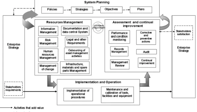
The general operation framework of the proposed MMF is presented in Figure 1.
The model begins and ends with the requirements and satisfaction of the stakeholders, using the concept proposed in maintenance management by Soderholmet al.32that is also in line with the ISO 9004:2000 standard40. Furthermore, the proposed model is designed to be efficiently used across the organization levels (reminding Pintelon and Gelders3 who proposed a model to be executed in three organizational activity levels). This model is composed of four modules or macro-processes, each one containing several processes that are specified in sub-processes and tasks.
The four macro-processes are: System Planning, Resources Management, Implementation and Operation, and Assessment and Continual Improvement.
The System Planning macro-process is constituted by four processes: Policies, Strategies, Objectives and Plans. The Resources Management processes are eight: Information Management, Risk Management, Human Resources Management, Management of Change, Documentation and Data Control System, Legal and Other Requirements, Outsourcing of asset management activities, and Infrastructure, Materials and Spare Parts Management. The Implementation and Operation macro-process is composed of the Implementation of Operational Procedures and of the Maintenance and Calibration of Tools, Facilities and Equipment processes. Finally, the Assessment and Continual Improvement macro-process is constituted by six processes: Performance and Condition Monitoring, Records Management, Management Review, Corrective and Preventive Actions, Audit and Continual Improvement.
It is noticeable that the System Planning process entails the top Direction of Maintenance. In the presented MMF, the medium levels perform the supporting processes (resources management) and control the maintenance execution. The level that executes maintenance also generates the data to be used for the continuous improvement of the maintenance function.
The structure of this model enables a link between the maintenance function and the other organizational functions. In the proposed model, each process (system planning, resources management, implementation and operation and assessment and continual improvement) is defined by UML diagrams using the ‘Eriksson–Penker Business Extensions’ and BPMN diagrams that indicate the sequence of activities for the execution of every stage.
4.
Business process modelling
According to Hammer and Champy41, a business process is ‘a collection of activities that takes one or more kinds of input and creates an output that is of value to the customer’. Davenport42 defines a (business) process as ‘a structured, measured set of activities designed to produce a specific output for a particular customer or market. It implies a strong emphasis on how work is done within an organization, in contrast to a product focus’s emphasis on what. A process is thus a specific ordering of work activities across time and space, with a beginning and an end, and clearly defined inputs and outputs: a structure for action’.
The modelling of business process, understood as the use of methods, techniques and software to design, enact, control and analyze operational processes involving humans, organizations, applications, documents and other sources of information43, has become an important subject especially since the 1990s, when companies were encouraged to think about ‘processes’ instead of ‘functions’ and ‘procedures’. Process thinking looks horizontally through the company for inducing improvement and measurement44.
From then on, BPM has been used in the industry to obtain a global vision of processes by means of support, control and monitoring activities45, to facilitate the comprehension of the business key mechanisms, to be a base for the creation of appropriate information systems, to improve the business structure and operations, to show the structure of changes made in the business, to identify outsourcing opportunities, to facilitate the alignment of ICT with the business needs and strategies46 and for several other activities such as the automatic processing of documents47.
The increase in the last years in the quantity of research on BPM, and the application of recent technological advances have propitiated the use of BPM in other fields such as planning of managerial resources (ERP), integration of managerial applications (EAI), management of relations with customers (CRM), management of work flows (WFM) and communication among users to facilitate management requirements45, 48.
Several benefits derived from the adoption of BPM have been identified in the literature: improvement of the accomplish-ment speed of business processes, increase of the clients’ satisfaction, optimization and elimination of unnecessary tasks, and incorporation of clients and partners in the business processes49.
Process modelling is an object of interest in many different fields, such as in the managerial area and software engineering. This is due to the fact that it not only describes processes, but in addition represents a preparatory stage for the improvement of business processes, process reengineering, technological transference and processes’ standardization50.
Software processes and business processes present certain similarities: they both try to capture the main features of a group of partially ordered activities carried out to achieve a specific goal. However, whereas the aim of a process software is to obtain a software product51, the aim of a business process is to obtain beneficial results (generally a product or service) for clients or others affected by the process52, 53.
Actually, the origins of different BPM languages are inspired by software modelling languages. The informatics approach defines modelling as the ‘designing of software applications before coding’54; this focus has contributed to the development of several languages and applications for code generation and processes automation, which have increased in quantity and diversity especially during the last two decades55.
5.
Modelling language and software tool selection process
Business processes are modelled using a Modelling Language, a standard that defines model elements and their meaning, allowing efficient, collaborative business process management across corporate boundaries and disciplines56.
A large number of BPM languages exist and several taxonomies have been proposed57. In a general classification, a modelling language can be graphical or textual and in a more detailed taxonomy, Ko et al.55 classify the BPM languages in relation to the BPM life cycle in: Graphical Standards (BPMN, UML), Execution Standards (BPEL, BPML, WSFL, XLANG), Interchange Standards (XPDL, BPDM) and Diagnosis Standards (BPRI, BPQL).
To select a suitable business modelling language to express the proposed MMF, the present investigation refers to the flow chart proposed by Koet al.55. This flow chart presents a sequential decisional process that leads to define the type of language to be used.
Considering that the objective of this research is to model a new business process (not a web service or an automation application nor a diagnosis), that this model has a private application (for internal BPM, not for collaboration business to business) and that it is desired to work with a graphical representation in order to facilitate the modelling process, the result from Ko’s et al. selection procedure indicates that the better choice is a Graphical Standard such as UML, BPMN, Event-driven Process Chains (EPC)58, RADs or simple flow charts.
Among all the mentioned standards, UML 2.1 using the ‘Eriksson–Penker Business Extensions’ and BPMN 1.0 were selected to model the proposed MMF. Both standards are maintained by the Object Management Group (OMG), an ‘international, open membership, not-for-profit computer industry consortium [. . .][that] develops enterprise integration standards for a wide range of technologies, and an even wider range of industries’54.
A further decision element was the availability to freely access the OMG website where it is possible to download the latest UML and BPMN specifications, and to consult a variety of resources about those standards.
UML was created in 1997 by Grady Booch, James Rumbaugh and Ivar Jacobson, who developed it from the union of their own methodologies. They proposed UML for the consideration of the OMG, being accepted as a standard on the same year it was proposed59.
For the modelling development of this research, UML will be accompanied by the ‘Eriksson-Penker Business Extensions’; these extensions are a set of specifications about the use of semantics to express the elements of the model in terms of business modelling6.
UML 2.1 specification is formed by 13 kinds of diagrams that show a specific static or dynamic aspect of a system.
BPMN’s first specification was released to the public in May 2004 with the objective to ‘provide a notation that is readily understandable by all business users, from the business analysts that create the initial drafts of the processes, to the technical developers responsible for implementing the technology that will perform those processes, and finally, to the business people who will manage and monitor those processes’60.
BPMN defines a business process diagram (BPD), which is formed by a set of graphical elements to represent activities and their flow60.
Regarding the software modelling tools, there is a large number of applications, some of them non-proprietary and others of proprietary type. The selection of the most appropriate tool depends on the particular modelling requirements and the project scope.
Although a simple graphical tool for diagrams development could be used, a professional software modelling tool including a business process repository offers interesting advantages (storing of elements, simulation, code generation, etc).
For this research, the selected software was Enterprise Architect 7.1; a UML analysis, design, documentation and project management CASE tool, including basic UML models plus testing, metrics, change management, defect tracking and user interface design extensions. This software is developed by Sparx Systems. Enterprise Architect 7.1 was chosen because of its features and its availability to support this research.
6.
Business architecture and modelling strategy
The general description of a system that identifies its purpose, vital functions, elements, processes and defines their interaction is called ‘business architecture’61. The OMG54 provides its definition: ‘Business architecture is a blueprint of the enterprise that provides a common understanding of the organization and is used to align strategic objectives and tactical demands [. . .] business architecture defines the structure of the enterprise in terms of its governance structure, business processes and business information’.
The objective of modelling the proposed MMF is to express its business architecture using documents and diagrams known as ‘artifacts’.
The general business architecture can be represented by three principal categories of data: the Business Context (models of the stakeholders relations, mission and vision statements, business goals and physical structure of the ‘as-is’ business), the Business Objects (a domain model of all objects of interest and their respective data) and the Business Workflows (BPDs representing the structures and objects defined in the Business Context and in the Business Objects diagrams. These BPDs show how objects work together to provide fundamental business activities).
In this paper the Business Context is represented by a Goals Diagram (Figure 2), the Business Objects by a Model of Classes and Objects (Figure 9) and the Business Workflows by a set of process diagrams (Figures 3–8).
Generally, the business architecture is organized hierarchically so that executives can observe how specific processes are aligned to support the organization’s strategic aims62.
The same hierarchical order is used to define the processes and sub-processes for the new MMF proposed in this investigation; the top–down approach will be initially preferred (starting modelling the top value chain process and later modelling the specific processes), not dismissing the possibility of using an inside–out approach in the following stages (starting modelling a particular specific process and then extending its influence around the general organization)63.
There is no defined way of naming process levels although frequently the smallest process diagram is called an activity (according to UML and BPMN standards).
A technical limit does not exist for a maximum number of processes’ subdivisions. The most important concept is to keep in mind that processes can be hierarchically arranged62.
Therefore, the proposed MMF has its own nomenclature to refer to its hierarchical levels.
Once having defined the operations to be modelled, the boundary of the system and after identifying its mission and vision, it is necessary to describe the business strategy to fulfil the goals set. These goals must be achieved through the operation of one or more business processes64.
class Goals
«goal»
To decrease the total maintenance costs
notes
Reducing the preventive and corrective maintenance costs
«goal»
To increase the assets av ailability
notes
Optimizing the preventive and corrective maintenance
«goal» Optimizing prev entiv e maintenanc e «goal» Optimizing correctiv e maintenanc e «goal» To reduce the failures rate «goal» To reduce the negativ e effects of failures {incomplete} «goal» To improv e the HR training «goal» To improv e the stocks managemen t «goal» To k eep an adequate infrastructure «goal» To k eep an effectiv e information system «goal» To keep effectiv e operational controls «goal»
To attend properly the non conformances detected in the maintenance management system notes Non conformances, corrective and preventive actions of the maintenance system detected during its operation or in audits «goal» To improv e continuously the maintenance system «goal»
Improv ing the execution of maintenance j obs notes In terms of time, procedures, use of resources, etc. «goal»
Improv ing the suitability of medium and short
term planning notes Generating suitables procedures, resources assignment, works planning, etc. {Incomplete}
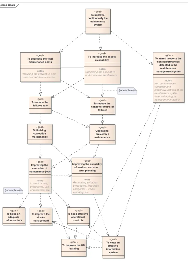
Figure 2. Goals tree diagram for the proposed MMF
In Figure 2 is represented an example of the goals tree that can be designed for the proposed MMF using a specific type of UML diagram: a class diagram. In this kind of diagram, a goal is described as a class object with the stereotypegoal. As in this project a new system is being designed, all the goals presented in the tree diagram are illustrative and of qualitative type.
For this particular MMF, the main goal is ‘to continuously improve the maintenance system’. This main goal depends on the fulfilment of other three goals (identified by a dependency line): to decrease the total maintenance cost, to increase the assets availability and to attend properly the non-conformances detected in the maintenance management system. It is necessary to notice that the first two aims (to decrease the total maintenance cost and to increase the assets availability) are contradictory goals. This contradictory feature is identified using an association line between the goal objects.
Moreover, the fulfilment of each one of the already-mentioned goals depends on another series of hierarchical goals (or sub-goals), which have to be totally or partially achieved. In the diagram, a tag with the legend ‘incomplete’ indicates this condition.
Every macro-process, process and activity described in the model is focused to the satisfaction of the objectives drafted in the goals tree diagram.
7.
Modelling the proposed maintenance management system
Following the mentioned top–down approach, the top value chain process of the proposed MMF (or level 0 process) is constituted by the already-mentioned four macro-processes: System Planning, Resources Management, Implementation and Operation and Assessment and Continual Improvement.
Subsequently, each macro-process is conformed by processes (level 1 processes) and each process can be subdivided into sub-processes (level 2 processes); finally each sub-process can be subdivided into activities (level 3 processes).
In Figure 3 appears a UML diagram made using the Eriksson–Penker Business Extensions. This diagram represents the top value chain process (or level 0). In a software platform, this diagram can also operate as a main menu to access to the rest of the processes.
analysis Business macro-processes
Macro-processes
System planning Resources Management
Implementation and Operation
Assessment and Continual Improvement Requirements
Satisfaction
«flow»
Figure 3. Macro-processes (top value chain process) of the proposed MMF
Every macro-process and process modelled has some invariable-related elements: one or several goals associated using a dependence relation with the stereotype achieve (these goals are derived from the goals tree); input resources, output resources, both linked using dependence relations, supply resources with a dependence relation and the stereotype supply and control resources having the stereotype control.
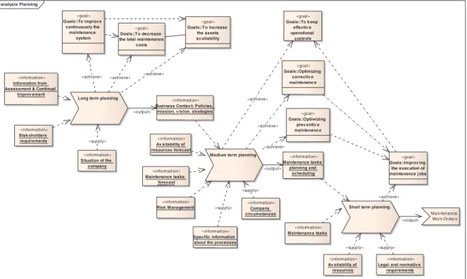
The first macro-process to model is System Planning module. Figure 4 shows the level 1 planning diagram, which was modelled using UML with the Eriksson–Penker Business Extensions. In this diagram, it is possible to identify the mentioned elements related to every process (goals, input, output, supply).
Figure 5. UML diagram of the Resources Management macro-process
Besides, in Figure 4 it can be observed that the three processes compose the total System Planning module: long-term planning, medium-term planning and short-term planning. The information and supplies required are identified in the diagram, as well as the goals to be achieved by each of the three processes.
It is interesting to notice that the output of each process is an input element for the next.
In a general way, this macro-process is defined as start inputs: the maintenance information for improvement (generated by the Assessment and Continual Improvement macro-process), the stakeholder’s requirements and information about the situation of the company. Other input elements are going to be needed for the entire planning development, but it is observed that the three mentioned as ‘start inputs’ are the earlier required initiating the process flow.
As a final output of this entire macro-process appears the maintenance work order, which has to be executed by the operative personnel. Besides the maintenance work order, there are other essential outputs generated during the planning as: the business context document (policies, mission, vision, agreements, strategies) and the planning and scheduling of maintenance tasks.
The procedures to carry out every planning process belong to level 2 and for this project are named sub-processes. On the whole, a procedure contains a more detailed description of the flow of activities to perform, the required, related and generated documents and the responsibilities for the performance.
If it is necessary due to the sub-process size or complexity, a level 3 diagram describing the activities can be made as well. Both, the level 2 diagram and the level 3 diagram could be produced using UML (if there is an important quantity of information inside it) or using BPMN (if the procedure is not too long). It is also possible to go beyond level 3 if more specific information is required.
The next macro-process to be modelled has to do with Resources Management processes, as Figure 5 shows using a UML diagram with the Eriksson–Penker Business Extensions.
The Resources Management module classifies the processes into the management of tangible resources, composed of three not-sequenced processes (Management of Outsourcing Activities Process, Infrastructure, Materials and Spare Parts Management Process and Human Resources Management Process) and into the management of intangible resources composed of three not-sequenced processes (Information Management and Control System of Documentation and Data Process, Risk Management Process, and Management of Change Process).
These processes are independent in their operation, although they are linked by their goals and are part of the same general system.
analysis Control and improv em...
Measurement, assessment and
improv ement
«goal»
Goals::To reduce the negativ e effects
of failures
«goal»
Goals::To reduce the failures rate
«goal» Goals::To improv e continuously the maintenance system «goal»
Goals::To attend properly the non conformances
detected in the maintenance management system «information» Maintenance process data «information» Maintenance tasks planning and scheduling «information» Business Contex t: Policies, mission, v ision,
strategies «resource» Suitable information system «information» Information from Assessment & Continual
Improv ement «information» Stak eholders requirements «information» Legal and normativ e requirements «supply» «output» «supply» «supply» «supply» «supply» «achieve» «achieve» «achieve» «achieve»
These six supporting processes share the same start input elements as well: information about the availability of resources, about the business context (policies, mission, vision, etc.) and about the planning and scheduling of maintenance tasks.
An appropriate execution of these supporting processes results in having suitable resources for the maintenance development (output elements).
The required procedures for every supporting process can be managed in level 3 diagrams, as previously explained in the System Planning macro-process.
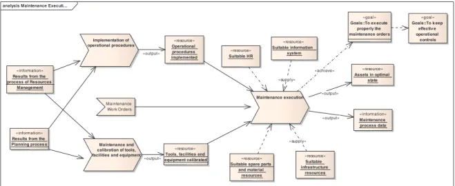
At first glance the macro-process for the maintenance execution, the Implementation and Operation macro-process (Figure 6), seems to be very simple, since its diagram does not have so many elements as the previous macro-processes. But in fact, this is the core process of the whole system65.
Beginning from the work order, maintenance tasks are developed according to the particular procedures defined by the organization, using the resources managed in the previous macro-process, and via the outputs supplied by the corresponding level 2 processes: the Implementation of Operational Procedures; and the Maintenance and Calibration of Tools, Facilities and Equipment Process.
From this development, the desirable outputs are: to have and/or to keep the assets in optimal state and, to compile outstanding data about maintenance process.
To have and/or to keep the assets in optimal state is an output that goes directly to satisfy a tangible necessity, generally outside the maintenance function. To compile outstanding data about maintenance process is a required input element in the Assessment and Continual Improvement macro-process.
The particular technical procedures inside the maintenance execution process, generally, involve very specific aspects that can be expressed using UML and BPMN.
These specific technical procedures depend on the kind of organization applying the system and as a core process, its performance is highly supported by the other macro-processes.
The remaining macro-process, Assessment and Continual Improvement, is presented in Figure 7. In its UML diagram, it is possible to identify the process start input: data about the maintenance process execution.
Further information is required as well (in diagram expressed as supplies). The desired output of this macro-process is the information for the improvement, which will be used by the following System Planning macro-process.
In this way, the system operates cyclically favoring the continuous improvement approach.
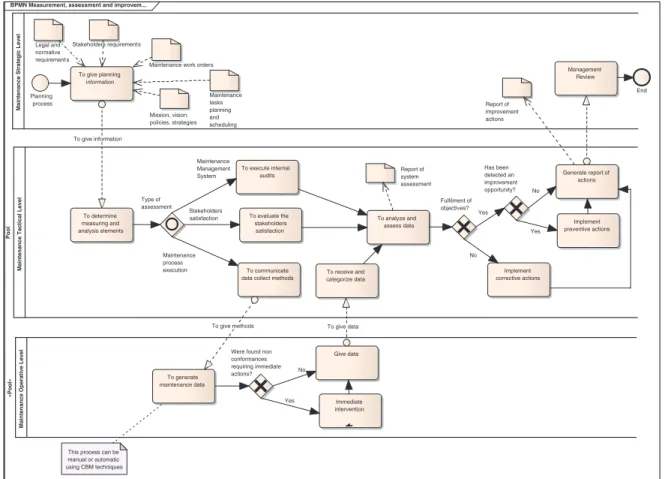
As an example of how the system operation can be detailed at deeper levels, Figure 8 shows a level 2 BPMN diagram, representing the process inside the Assessment and Continual Improvement module, where the working flows and activities necessary to achieve the corresponding goals are identified.
In this BPMN diagram can also be identified as the activities corresponding to the six elements constituting this macro-process (see Figure 1).
Figure 8 shows the basic elements of a BPMN diagram: flow objects, connection objects, swimlanes and artifacts66. Also the six processes inside can be identified as activities.
Inside every activity modelled in the BPMN diagram it is also possible to add more specific procedures, being identified by consecutive levels numeration. Different macro-processes can be conformed by different number of levels, depending on the complexity of the procedures to model.
Besides the diagrams used to symbolize process workflows, there are other kinds of diagrams (called also artifacts) that are useful for having a complete view of the whole system and are indispensable if there is an idea of developing an informatics application.
Those diagrams are categorized by the UML 2.1 standard into Structural diagrams (defining the static architecture of a model) and Behavioral diagrams (representing the interaction and instantaneous states within a model as it ‘executes’ over time).
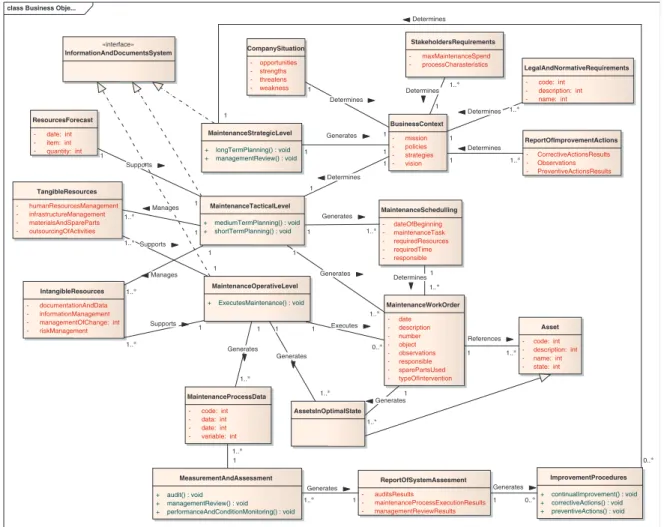
A structural diagram (a class diagram) was used before to symbolize the goals tree (Figure 2). There are other different kinds of structural diagrams. In order to exemplify, Figure 9 shows another important structural diagram. This class diagram represents a conceptual model, defining the business concepts about a maintenance management system and how they are related among them.
A conceptual diagram identifies the important concepts related to a specific context and it can be useful to model the business resources, rules and goals67.
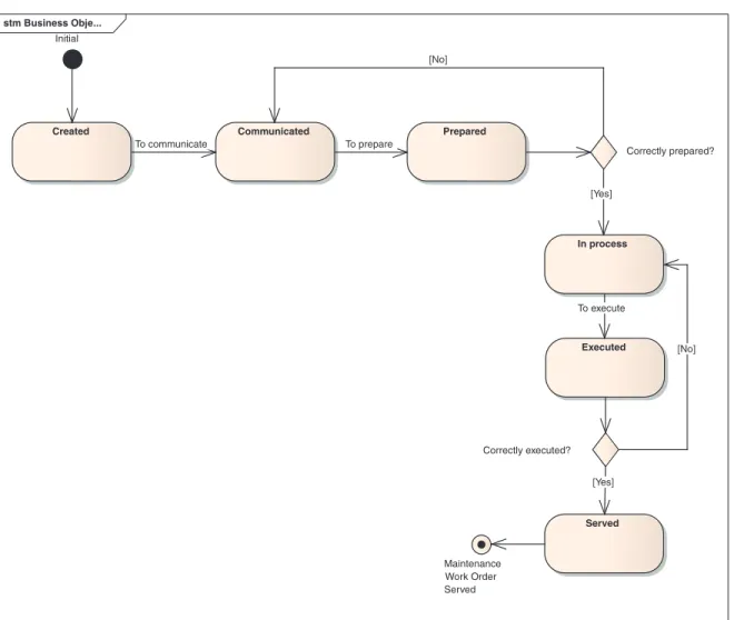
Regarding behavioral diagrams, there are also several kinds: use case diagrams, sequence diagrams, state diagrams, etc. Figure 10 shows a state diagram detailing the transitions or changes of state that an object (in this case a maintenance work order) can go through in the system.
State diagrams show how an object moves from one state to another and the rules that govern that change. State charts typically have a start and an end condition67.
stm Business Obje...
Initial
Created Communicated Prepared
In process Correctly executed? Executed Correctly prepared? Served Maintenance Work Order Served [No] [Yes] [No] [Yes] To execute To prepare To communicate
Figure 10. UML state diagram for a maintenance work order
All diagrams appearing in this article were made using Enterprise Architect 7.1. This software was perceived as agile and easy to use, with a variety of online resources.
8.
ICT issues related to the MMF implementation
An important distinctive attribute of the proposed MMF is that it has been modelled using the BPM methodology, UML and BPMN languages.
This attribute provides the MMF with integration capacities and flexibility to take advantage of the ICT.
For instance, from a complete description of the MMF operation algorithms using UML and BPMN diagrams, it is relatively not difficult to generate code for the development of a software application that executes the MMF modules68, 69.
Some of the ERP systems that currently exist in the market have maintenance management modules, and there are likewise, some software applications specific for asset management70 (EAM systems); nevertheless, practical experience reveals that there are still several novel functions that can be added into a new system to improve maintenance management. Most of these functions are related to e-maintenance and can be incorporated into the proposed MMF through UML and BPMN models as well, specifically looking for coordination in real time among CMMS, RCM and CBM systems.
Although the e-Maintenance term has been used since 2000 as a component of e-Manufacturing, at present there is not yet a standardized definition of e-Maintenance given by an official institution71.
From a pragmatic point of view, we may say that e-Maintenance is ‘the set of maintenance processes that uses the e-technologies to enable proactive decisions in a particular organization’ (definition partially derived from Levrat et al.72).
Such e-maintenance processes are supported by means of a variety of hardware and software technologies as the wireless and mobile devices, embedded systems, web-based applications, P2P networks, multi-agent applications, specific software architectures, among others.
This variety of technologies implies the existence of multiple communication protocols, data connections, configurations, etc. In this respect, several standards have been developed in order to obtain interconnection and interoperability among the different systems.
The Machinery Information Management Open Systems Alliance or MIMOSA is an important not-for-profit trade association dedicated to developing and encouraging the adoption of open information standards in operations and maintenance (O&M) just to support interoperability73.
MIMOSA standards are interesting references for the proposed MMF because of two main reasons: the former is that MIMOSA standards are expressed using UML language; the latter is that MIMOSA has developed two types of information-exchanging open standards that are also related to the processes to be developed in the proposed MMF: a standard for management applications (OSA-EAITM) and a standard for condition-based maintenance (OSA-CBMTM). Both standards provide metadata reference libraries and a series of information-exchange standards using XML and SQL.
Therefore, it is necessary to consider the adoption of MIMOSA standards to continue modelling deeper levels of the MMF particularly for the operation of e-maintenance processes.
Concerning these e-maintenance processes, although e-maintenance can be characterized as a technique, the general idea of this project (based on Iung et al. 200974) is considering e-maintenance as a philosophy supporting the operation of the entire MMF and making possible the information exchange among remote elements. This philosophy allows the decision making and the fulfilment of the maintenance global objectives depending on collaboration, which implies the use of ICT.
The majority of the e-maintenance processes to be included in the proposed MMF involve the realization of the classical maintenance management activities but using e-technologies, in a distance environment. The proposed MMF becomes a CMMS system with remote capabilities.
However, the use of e-technologies and large volumes of different data necessarily increases the possibilities to create new emerging e-maintenance processes.
During the development of this MMF, several novel e-maintenance processes have been identified as required, particularly processes related to an integration and exchange of information among CMMS, RCM and CBM systems75. This e-maintenance integration is able to optimize the decision-making processes related to the feasibility of the maintenance strategies and programs.
In general terms, this integration works as follows76: using the information managed by the CMMS (saved inside each module of the proposed MMF), the RCM methodology is applied to the pre-defined system(s), defining the operational context and the processes involved, doing the FMECA analysis and selecting the appropriate maintenance policies. From the RCM analysis, it is possible to detect the necessity of applying CBM in some particular elements in order to generate important economical savings. The real-time CBM signals feed the CMMS and subsequently the RCM, generating an automatic suggestion if a maintenance strategy has to be updated according to its behavior. Then, the RCM is applied again and the improving cycle begins one more time. Moreover, the integration of this information can maximize the effectiveness of the diagnosis: the CBM signals are related to the most critical and frequent failures modes of the RCM analysis, allowing time savings in corrective and preventive actions.
The specific operational characteristics of those e-maintenance processes, the ICT related to them and the additional inter-operability standards required for their implementation (i.e. ISO 18435, ISO 62264, OPC standards, etc.) have to be defined according to the special requirements of the specific industrial sector that applies for the proposed MMF, and they are material for another paper.
9.
Conclusions
In the historical development of maintenance, several models and frameworks looking for the optimal maintenance management structure have been developed34.
Among all those proposals, PAS 55 standard emerges in 2004, as a complete framework, not only for maintenance but also for management of the entire life cycle of assets.
Besides, PAS 55 involves a set of desirable characteristics and best practices identified as necessaries for the operation of a modern and efficient MMF, as the input–output processes approach, the objectives entailment, the orientation to new technologies and the continuous improvement approach.
Then, this article shows the process of modelling an MMF that represents the general requirements of PAS 55.
The flow diagrams and processes proposed inside the MMF are a representation of how the PAS 55 structure can be implemented in an organization. We have to remember that PAS 55 declares what has to be done, but not exactly how to do it. For this reason, each company is able to develop its own specific techniques and methodologies to fulfil the PAS 55 requirements.
For the realization of this project, the modelling work involved researching about the basic concepts in the area (business process, modelling, modelling language, business architecture, etc.) to select the most suitable language and software tool for the case.
UML 2.1 and BPMN 1.0 were the modelling languages selected to express the proposed MMF, due to their recognition as international standards, their increasing use in successful maintenance projects (e.g. PROTEUS project77, among others) and their interesting capabilities.
Later, a modelling methodology was chosen to represent the system architecture, and to develop the structural and behavioral diagrams exposed in this article.
Summarizing, the general steps to model the proposed MMF and that have been shown in this article are: (i) PAS 55 analysis, (ii) design of the conceptual MMF according to standards, (iii) selection of modelling language and modelling software tool, (iv) definition of the business architecture, (v) modelling of goals tree, (vi) identification of top value chain process, (vii) modelling of involved processes and activities, (viii) tracing several UML and BPMN diagrams to represent specific features of the system and (ix) analysis of the ICT issues related to the implementation of the MMF and conclusions.
The use of process modelling languages (UML 2.1 and BPMN 1.0) gives to the MMF the interesting possibility of generating code and the subsequent creation of software as an alternative from the ERP, CMMS and EAM commercial systems.
Code generation and the development of a software application involve a hard work detailing the data and operation models for the MMF, a profound working out of algorithms and artifacts describing the use of the tools and techniques required for the operation of the MMF. Also, the identification and interpretation of the interoperability standards required according to the ICT execution of the MMF modules is necessary.
In this respect, the operation of the system through e-maintenance processes78 is a recommended approach.
Finally, it is important to mention that the activities’ flow and processes modelled in this paper correspond mainly to the real operation of PAS 55 in a leading Spanish enterprise of the energy sector, and that the project of the e-maintenance integration among CMMS, RCM and CBM for decision-making is actually, being implemented in a transformer and in a water pump76, equipments of the same energy production and distribution enterprise.
Acknowledgements
This research was possible thanks to the support of the Mexican Council of Science and Technology (CONACYT) and the Spanish Ministry of Science and Innovation (DPI 2008:01012). The authors would like also to thank Antonio Sola and José Manuel Framiñán for their precious suggestions.
References
1. Sherwin D. A review of overall models for maintenance management. Journal of Quality in Maintenance Engineering2000;6(3):138--164. 2. Cholasuke C, Bhardwa R, Antony J. The status of maintenance management in UK manufacturing organisations: Results from a pilot survey.
Journal of Quality in Maintenance Engineering2004;10(1):5.
3. Pintelon LM, Gelders LF. Maintenance management decision making.European Journal of Operational Research1992;58(3):301--317. 4. Prasad Mishra R, Anand D, Kodali R. Development of a framework for world-class maintenance systems.Journal of Advanced Manufacturing
Systems2006;5(2):141--165.
5. Vanneste SG, Van Wassenhove LN. An integrated and structured approach to improve maintenance.European Journal of Operational Research
1995;82(2):241--257.
6. Object Management Group Website. Available at: http://www.bpmi.org/ [20 March 2009].
7. Framiñán J. Introducción a la Arquitectura y Desarrollode Sistemas de Información Basados en la Web. Secretariado de Publicacionesde la Universidad de Sevilla: Sevilla, 2008.
8. PAS 55-1:2008. Asset management. Specification for the optimized management of physical assets. PAS 55-1:2008, BSI, U.K., 2008.
9. Qiu XB, Wimmer W. Applying object orientation and component technology to architecture design of power system monitoring.Proceedings of the International Conference on Power System Technology(POWERCON 2000), Perth, WA, Australia, vols. 1–3, 2000; 589--594.
10. Thurston MG. An open standard for web-based condition-based maintenance systems.Proceedings of the IEEE Systems Readiness Technology Conference(IEEE AUTOTESTCON 2001), Valley Forge, PA, U.S.A., 2001; 401--415.
11. Huang XQ, Pan HX, Yao ZT, Ma QF, Cai JJ. The study on expert system of state monitoring and fault diagnosis for gearbox.Proceedings of the Sixth International Symposium on Test and Measurement, Dalian, China, vols. 1–9, 2005; 1867--1870.
12. Palluat N, Racoceanu D, Zerhouni N. A neuro-fuzzy monitoring system application to flexible production systems.Computers in Industry2006;
57(6):528--538.
13. Xing W, Jin C, Ruqiang L, Weixiang S, Guicai Z, Fucai L. Modeling a web-based remote monitoring and fault diagnosis system with UML and component technology.Journal of Intelligent Information Systems2006;27(1):5--19.
14. Dong X, Liu Y, LoPinto F, Scheibe K, Sheetz S. Information model for power equipment diagnosis and maintenance.Proceedings of the IEEE Power Engineering Society Winter Meeting, New York, NY, U.S.A., vols. 1–2, 2002; 701--706.
15. Min-Hsiung H, Rui-Wen H, Fan-Tien C. An e-diagnostics framework with security considerations for semiconductor factories.Proceedings of the Semiconductor Manufacturing Technology Workshop, Hsinchu, Taiwan, 2004; 37--40.
16. Chen B, Gao X, Zhao Z. Research on a remote distributed fault diagnosis system based on UML and CORBA. Proceedings of the First International Conference on Maintenance Engineering, Chengdu, China, 2006; 363--367.
17. Mouritz D. An integrated system for managing ship repair operations. International Journal of Computer Integrated Manufacturing 2005;
18(8):721--733.
18. Cerrada M, Cardillo J, Aguilar J, Faneite R. Agents-based design for fault management system in industrial processes. Computers in Industry
2007;58(4):313--328.
19. Li L, Chen T, Guo B. Simulation modeling for equipment maintenance support system based on stochastic service resource management object.Journal of National University of Defense Technology2010;2(32).
20. Belmokhtar O, Ouabdesselam A, Aoudia M. Conception of an information system for the maintenance management.Proceedings of the Fifth International Conference on Quality, Reliability and Maintenance, Oxford, U.K., 2004; 141--148.
21. Nordstrom L, Cegrell T. Extended UML Modeling for risk management of utility information system integration.Proceedings of the IEEE Power Engineering Society General Meeting, San Francisco, CA, U.S.A., vols. 1–3, 2005; 913--919.
22. Keraron Y, Bernard A, Bachimont B. An UML model of the technical information system to enable information handling and recording during the product life cycle.Proceedings of the Fourth International Conference on Product Lifecycle Management, Kilometro Rosso, Bergamo, Italy, 2007; 363--372.
23. Sadegh P, Concha J, Stricevic S, Thompson A, Kootsookos P. A framework for unified design of fault detection and isolation and optimal maintenance policies.Proceedings of the 2006 American Control Conference, Minneapolis, MN, U.S.A., 2006; 3749--3756.
24. Reiner J, Koch J, Krebs I, Schnabel S, Siech T. Knowledge management issues for maintenance of automated production systems.Proceedings of the IFIP International Conference on Human Aspects in Production Management, Karlsruhe, Germany, vol. 160, 2005; 229--237.
25. Rasovska I, Chebel-Morello B, Zerhouni N. A mix method of knowledge capitalization in maintenance. Journal of Intelligent Manufacturing
2008;19(3):347--359.
26. Trappey A, Hsiao D, Ma L, Chung YL. Maintenance chain integration using petri-net enabled prometheus MAS modeling methodology.
Proceedings of the 13th International Conference on Computer Supported Cooperative Work in Design, Santiago, Chile, 2009; 238--245. 27. Bangemann T, Thomesse J, Lepeuple B, Diedrich C. PROTEUS—Providing a concept for integrating online data into global maintenance
strategies.Proceedings of the Second IEEE International Conference on Industrial Informatics, Berlin, Germany, 2004; 120--124. 28. Campbell JD, Reyes-Picknell J.Uptime: Strategies for Excellence in Maintenance Management. Productivity Press: New York, 1995. 29. Wireman T.Development Performance Indicators for Managing Maintenance. Industrial Press: New York, 1998.
30. Duffuaa S, Raouf A, Dixon Campbell J.Planning and Control of Maintenance Systems(Spanish edn). Limusa: México, 2000.
31. Waeyenbergh G, Pintelon L. A framework for maintenance concept development. International Journal of Production Economics 2002;
77(1):299--313.
32. Söderholm P, Holmgren M, Klefsjö B. A process view of maintenance and its stakeholders. Journal of Quality in Maintenance Engineering
2007;13(1):19--32.
33. Crespo Márquez A.The Maintenance Management Framework. Models and Methods for Complex Systems Maintenance. Springer: U.K., 2007. 34. López Campos M, Crespo Márquez A. Review, classification and comparative analysis of maintenance management models. Journal of
Automation, Mobile Robotics and Intelligent Systems2009;3(3):110--115.
35. ISO 9001: 2008. Quality Management Systems. Requirements.ISO 9001:2008, ISO, Geneva, 2008.
36. Corbett C. Global diffusion of ISO 9000 certification through supply chains. International Series in Operations Research and Management Science, vol. 119, 2008; 169--199.
37. PAS 55-2:2008. Asset Management. Guidelines for Aapplication of PAS 55-1.PAS 55-2:2008, BSI, U.K., 2008.
38. Crespo A, Gupta J. Contemporary maintenance management: Process, framework and supporting pillars.Omega the International Journal of Management Science2006;34:313--326.
39. Crespo Márquez A, Moreu de León P, Gómez Fernández J, Parra Márquez C, López Campos M. The maintenance management framework: A practical view to maintenance management. Journal of Quality in Maintenance Engineering2009;15(2):167--178.
40. ISO 9004:2000. Quality Management Systems—Guidelines for Performance Improvements. ISO 9004:2000, ISO, Geneva, 2000. 41. Hammer M, Champy J.Reengineering the Corporation. Harper: New York, 1993.
42. Davenport T.Process Innovation:Reengineering Work through Information Technology. Harvard Business School Press: Boston, 1993. 43. Van der Aalst W. Don’t go with the flow: Web services composition standards exposed.IEEE Intelligent Systems 2003;18(1):72--76. 44. Rolstadås Asbjørn.Performance Management: A Business Process Benchmarking Approach. Kluwer: England, 1995.
45. Russel N, VanderAlst W, Hofstede A, Wohed P. On the suitability of UML Activity Diagrams for Business Process Modelling.Proceedings of the Third Asia-PAcific Conference on Conceptual Modelling (APCCM),Conferences in Research and Practice Information Technologies, Hobart, Tasmania, Australia, vol. 53, 2006; 104--195.
46. Beck K, Joseph J, Goldszmidt G. Learn business process modeling basics for the analyst. IBM, 2005. Available at: http://www-128ibm.com/developersworks/library/wsbpm4analyst [April 2008]
47. Kalnins A, Vitolins V. Use of UML y model transformations for workflow process definitions.Communications of the Conference Baltic DBIS
Vilnius Technika, 2006; 3--15.
48. Ramzan S, Ikram N. Requirement change management process models: An Evaluation.Proceedings of Software Engineering Conference. Acta Press, Anaheim, CA, U.S.A., 2007.
49. Pérez J, Ruiz F, Piattini M. Model driven engineering aplicado a business process management.Informe Técnico UCLM-TSI-002, 2007. 50. Succi G, Predonzani P, Vernazza T.Business Process Modeling with Objects, Costs and Human Resources. Systems Modeling for Business Process
Improvement. Artech House: London, 2000; 47--60.
51. Acuña S, Ferré X. Software Process Modelling.Proceedings of the Fifth World Multiconference on Systemics, Cybernetics and Informatics (SCI 2001), Orlando, FL, 2001; 1--6.
52. Sharp A, McDermott P.Workflow Modeling: Tools for Process Improvement and Application Development. Artech House: London, 2000. 53. Crespo Márquez A.Dynamic Modelling for Supply Chain Management. Front-end, Back-end and Integration Issues. Springer: London, 2010; 297. 54. OMG Business Architecture Working Group Website. Available at: http://www.bawg.omg.org/ [March 2009].
55. Ko R, Lee S, Lee E. Business process management (BPM) standards: A survey.Business Process Management Journal2009;15(5):744--791. 56. IDS Scheer Website. Available at: http://www.idsscheer.com/en/ARIS/Modeling_Standards/80850.html [March 2009].
57. Giaglis G. A taxonomy of business process modelling and information systems techniques.International Journal of Flexible Manufacturing Systems2001;13(2):209--228.
58. Scheer A.Architecture of Integrated Information Systems: Foundations of Enterprise Modelling. Springer: New York, 1992. 59. Schmuller J.Sams Teach Yourself UML in 24 Hours. Macmillan Computer Pub.: U.S.A., 2001.
60. White S. Introduction to BPMN. OMG Website. Available at: http://www.bpmn.org/ [January 2010].
61. Gharajedaghi J.Systems Thinking. Managing Chaos and Complexity:A Plataform for Designing Business Architecture. Elsevier: U.S.A., 1999. 62. Harmon P. Business Process Change:A Guide for Business Managers and BPM and Six Sigma Professionals. Elsevier: Boston, 2007. 63. Recker J. Process modeling in the 21st century.BPTrends2006. Available at: http://www.bptrends.com [January 2010].
64. Vasconcelos A, Caetano A, Neves J, Sinogas P, Mendes R, Tribolet J. A framework for modeling strategy, business processes and information systems. Proceedings of the Fifth International Enterprise Distributed Object Computing Conference(EDOC’2001). IEEE Computer Society: Silver Spring, MD, 2001.
65. Porter ME.Competitive Advantage:Creating and Sustaining Superior Performance. The Free Press: New York, 1985. 66. OMG UML Semantics ver. 1.1. Available at: ftp://ftp.omg.org/pub/docs/ad/97-08-04.pdf [20 March 2009]. 67. Milestone Consulting,Modelado de Negocios con UML y BPMN. Milestone Consulting Editions: México, 2001.
68. Hauser R, Koehler J. Compiling Process Graphs into Executable Code(Lecture Notes in Computer Science, vol. 3286). Springer: Berlin, 2004; 317--336.
69. Ouyang C, Dumas M, Breutel S, Ter Hofstede A.Translating Standard Process Models to BPEL(Lecture Notes in Computer Science, vol. 4001). Springer: Berlin, 2006; 417--432.
70. Strub J, Jakovljevic P. EAM versus CMMS.CMMScity. Available at: http://www.cmmscity.com/index.htm [February 2010].
71. Muller A, Crespo Márquez A, Iung B. On the concept of e-maintenance: Review and current research.Reliability Engineering and System Safety
2008;93:1165--1187.
72. Levrat E, Iung B, Crespo Márquez A. E-maintenance: Review and conceptual framework.Production Planning and Control2008;19(4):408--429. 73. MIMOSA. An Operations and Maintenance Information Open System Alliance. Available at: http://www.mimosa.org [May 2010].
74. Iung B, Levrat E, Crespo Márquez A, Erbe H. Conceptual Framework for e-Maintenance: Illustration by e-Maintenance technologies and platforms. Annual Reviews in Control2009;33:220--229.
75. Niu G, Yang BS, Pecht M. Development of an optimized condition-based maintenance system by data fusion and reliability-centered maintenance.Reliability Engineering and System Safety2010;95(7):786--796.
76. López Campos M, Fumagalli L, Gómez Fernández J, Crespo Márquez A, Macchi M. UML model for integration between RCM and CBM in an e-maintenance architecture.Proceedings of the First IFAC Workshop on Advanced Maintenance Engineering Services and Technology(A-MEST), Lisbon, Portugal, 2010; 133--138.
77. Bangemann T, Rebeuf X, Reboul D, Schulze A, Szymanski J, Thomesse J, Thron M, Zerhouni N. PROTEUS-Creating distributed maintenance systems through an integration platform.Computers in Industry2006;57(6):539--551.
78. Crespo Márquez A, Iung B. Special issue on e-maintenance.Computers in Industry2006;57(1):473--475.
Authors’ biographies
M. A. López Camposis a PhD Student in Industrial Management at the School of Engineering, University of Seville, Spain. She is an Industrial Engineer from the University of Guadalajara, México. She has a scholarship financed by the Mexican Council of Science and Technology. Sho also participates in a research team related to maintenance and dependability management, lead by Prof. Crespo. Her research works have been published in journals such as the Journal of Automation, Mobile Robotics and Intelligent Systems and Journal of Quality in Maintenance Engineering, among others. Her interests include maintenance, business process management, quality and engineering educational methodologies.
A. Crespo Márquez is currently Full Professor at the School of Engineering of the University of Seville, in the Department of Industrial Management. He holds a PhD in Industrial Engineering from the same university. His research works have been published in journals such as theInternational Journal of Production Research,International Journal of Production Economics,European Journal of Operations Research,Journal of Purchasing and Supply Management,International Journal of Agile Manufacturing, Omega,Journal of Quality in Maintenance Engineering,Decision Support Systems,Computers in Industry and Reliability Engineering and System Safety, International Journal of Simulation and Process Modeling, among others. Prof. Crespo is the author of four books, the last two with Springer Verlag in 2007 and 2010 about maintenance and supply chain management, respectively. Prof. Crespo leads the Spanish Research Network on Dependability Management and the Spanish Committee for Maintenance Standardization (1995–2003). He also leads a research team related to maintenance and dependability management currently with five PhD students and four researchers. He has extensively participated in many engineering and consulting projects for different companies, for the Spanish Departments of Defense, Science and Education as well as for the European Commission (IPTS). He is the President of INGEMAN (a National Association for the Development of Maintenance Engineering in Spain) since 2002.